EP1032783B1 - Valve actuator - Google Patents
Valve actuator Download PDFInfo
- Publication number
- EP1032783B1 EP1032783B1 EP98958211A EP98958211A EP1032783B1 EP 1032783 B1 EP1032783 B1 EP 1032783B1 EP 98958211 A EP98958211 A EP 98958211A EP 98958211 A EP98958211 A EP 98958211A EP 1032783 B1 EP1032783 B1 EP 1032783B1
- Authority
- EP
- European Patent Office
- Prior art keywords
- cylinder
- piston
- valve actuator
- fact
- valve
- Prior art date
- Legal status (The legal status is an assumption and is not a legal conclusion. Google has not performed a legal analysis and makes no representation as to the accuracy of the status listed.)
- Expired - Lifetime
Links
- 230000008878 coupling Effects 0.000 claims description 28
- 238000010168 coupling process Methods 0.000 claims description 28
- 238000005859 coupling reaction Methods 0.000 claims description 28
- 238000007789 sealing Methods 0.000 claims description 21
- 230000003213 activating effect Effects 0.000 claims description 20
- 239000007788 liquid Substances 0.000 claims description 12
- 238000010276 construction Methods 0.000 claims description 5
- 239000000126 substance Substances 0.000 claims description 3
- 230000002401 inhibitory effect Effects 0.000 claims 2
- 238000004519 manufacturing process Methods 0.000 description 2
- 238000000034 method Methods 0.000 description 2
- 230000004913 activation Effects 0.000 description 1
- 238000005553 drilling Methods 0.000 description 1
- 239000007789 gas Substances 0.000 description 1
- 238000001746 injection moulding Methods 0.000 description 1
- 239000000203 mixture Substances 0.000 description 1
- 238000012986 modification Methods 0.000 description 1
- 230000004048 modification Effects 0.000 description 1
Images



Classifications
-
- F—MECHANICAL ENGINEERING; LIGHTING; HEATING; WEAPONS; BLASTING
- F16—ENGINEERING ELEMENTS AND UNITS; GENERAL MEASURES FOR PRODUCING AND MAINTAINING EFFECTIVE FUNCTIONING OF MACHINES OR INSTALLATIONS; THERMAL INSULATION IN GENERAL
- F16K—VALVES; TAPS; COCKS; ACTUATING-FLOATS; DEVICES FOR VENTING OR AERATING
- F16K15/00—Check valves
- F16K15/20—Check valves specially designed for inflatable bodies, e.g. tyres
-
- B—PERFORMING OPERATIONS; TRANSPORTING
- B60—VEHICLES IN GENERAL
- B60S—SERVICING, CLEANING, REPAIRING, SUPPORTING, LIFTING, OR MANOEUVRING OF VEHICLES, NOT OTHERWISE PROVIDED FOR
- B60S5/00—Servicing, maintaining, repairing, or refitting of vehicles
- B60S5/04—Supplying air for tyre inflation
-
- F—MECHANICAL ENGINEERING; LIGHTING; HEATING; WEAPONS; BLASTING
- F16—ENGINEERING ELEMENTS AND UNITS; GENERAL MEASURES FOR PRODUCING AND MAINTAINING EFFECTIVE FUNCTIONING OF MACHINES OR INSTALLATIONS; THERMAL INSULATION IN GENERAL
- F16L—PIPES; JOINTS OR FITTINGS FOR PIPES; SUPPORTS FOR PIPES, CABLES OR PROTECTIVE TUBING; MEANS FOR THERMAL INSULATION IN GENERAL
- F16L37/00—Couplings of the quick-acting type
- F16L37/08—Couplings of the quick-acting type in which the connection between abutting or axially overlapping ends is maintained by locking members
- F16L37/12—Couplings of the quick-acting type in which the connection between abutting or axially overlapping ends is maintained by locking members using hooks, pawls, or other movable or insertable locking members
-
- F—MECHANICAL ENGINEERING; LIGHTING; HEATING; WEAPONS; BLASTING
- F16—ENGINEERING ELEMENTS AND UNITS; GENERAL MEASURES FOR PRODUCING AND MAINTAINING EFFECTIVE FUNCTIONING OF MACHINES OR INSTALLATIONS; THERMAL INSULATION IN GENERAL
- F16L—PIPES; JOINTS OR FITTINGS FOR PIPES; SUPPORTS FOR PIPES, CABLES OR PROTECTIVE TUBING; MEANS FOR THERMAL INSULATION IN GENERAL
- F16L37/00—Couplings of the quick-acting type
- F16L37/08—Couplings of the quick-acting type in which the connection between abutting or axially overlapping ends is maintained by locking members
- F16L37/12—Couplings of the quick-acting type in which the connection between abutting or axially overlapping ends is maintained by locking members using hooks, pawls, or other movable or insertable locking members
- F16L37/18—Joints tightened by eccentrics or rotatable cams
-
- Y—GENERAL TAGGING OF NEW TECHNOLOGICAL DEVELOPMENTS; GENERAL TAGGING OF CROSS-SECTIONAL TECHNOLOGIES SPANNING OVER SEVERAL SECTIONS OF THE IPC; TECHNICAL SUBJECTS COVERED BY FORMER USPC CROSS-REFERENCE ART COLLECTIONS [XRACs] AND DIGESTS
- Y10—TECHNICAL SUBJECTS COVERED BY FORMER USPC
- Y10T—TECHNICAL SUBJECTS COVERED BY FORMER US CLASSIFICATION
- Y10T137/00—Fluid handling
- Y10T137/3584—Inflatable article [e.g., tire filling chuck and/or stem]
- Y10T137/36—With pressure-responsive pressure-control means
-
- Y—GENERAL TAGGING OF NEW TECHNOLOGICAL DEVELOPMENTS; GENERAL TAGGING OF CROSS-SECTIONAL TECHNOLOGIES SPANNING OVER SEVERAL SECTIONS OF THE IPC; TECHNICAL SUBJECTS COVERED BY FORMER USPC CROSS-REFERENCE ART COLLECTIONS [XRACs] AND DIGESTS
- Y10—TECHNICAL SUBJECTS COVERED BY FORMER USPC
- Y10T—TECHNICAL SUBJECTS COVERED BY FORMER US CLASSIFICATION
- Y10T137/00—Fluid handling
- Y10T137/3584—Inflatable article [e.g., tire filling chuck and/or stem]
- Y10T137/3724—With coupling means
Definitions
- the present invention relates generally to a valve actuator for valves having a spring-force operated valve core pin, according to the preamble portion of claim 1.
- a valve connector comprising a valve actuator according to the preamble portion of claim 1 and having an activating pin which is designed as a piston rod of a piston movable in a cylinder and which can move towards a valve under the pressure of liquid and/or gaseous media from a pressure source is well-known from WO-A-96/10903
- the conduction channel for conducting pressure media from the cylinder to the coupling section is designed as a central bore of the piston and a radial bore in the piston rod and is controlled by an O-ring of the housing to be open toward the coupling section in the first position of the piston. In the second position of the piston, the passage of the pressure media is inhibited by the O-ring which sealingly cooperates with the piston rod.
- one disadvantage of conventionel activating pins is their several tiny parts. The complexity of these conventional activating pins makes production of conventional valve connectors more expensive than necessary.
- valve actuator of the present invention and embodiments thereof are subjects of claims 1 and 2 to 17, respectively.
- a valve connector and a pressure vessel or hand pump, comprising a valve actuator of the present invention are subjects of claims 18 and 19, respectively.
- Claim 20 is directed to the use of the valve actuator in a stationary construction.
- the present invention provides a valve actuator which comprises an inexpensive combination of a cylinder, within in which the piston driving the activating pin moves, and an activating pin, having a simple construction.
- This combination can be used in stationary constructions, such as chemical plants, where the activating pin engages the spring force operated core pin of a valve (e.g. a release valve), as well as in valve connectors (e.g. for inflating vehicle tires).
- a valve e.g. a release valve
- valve connectors e.g. for inflating vehicle tires.
- This valve actuator features a piston having a piston ring fitting into the cylinder, where the piston, in its first position, is at a first predetermined distance from the first end of the cylinder.
- the cylinder wall comprises a conducting channel for allowing conduction of gaseous and/or liquid media between the cylinder and the coupling section when the piston is in the first position, whereas conduction of gaseous and/or liquid media between the cylinder and the coupling section is inhibited by the piston when the piston is in the second position.
- valve actuator of the present invention features a conducting channel from the pressure source to the valve to be actuated that comprises an enlargement of the cylinder diameter which is arrangend around the piston of the activating pin in the bottom of the cylinder, when the piston is in the first position, enabling the medium from the pressure source to flow to the opened spring-force operated valve core pin, e.g. from a Schrader valve.
- the enlargement of the cylinder's diameter may be uniform, or the cylinder wall may contain one or several sections near the bottom of the cylinder where the distance between the center line of the cylinder and the cylinder wall increases so that gaseous and/or liquid media can freely flow around the edge of the piston ring when the piston is in the first position.
- a variant of this embodiment has a valve actuator arrangement of which its cylinder has the enlargement of the diameter twice.
- the distance between the enlargements can be the same as the distance between the sealing levels of the sealing means.
- the valve actuator may comprise a cylinder with three enlargements. It is however also possible to connect valves of different sizes to a valve actuator having a single arrangement for the enlargement of the diameter of the cylinder. Now therefore the number of enlargements can be different from the number of different valve sizes of valves which can be coupled.
- Another embodiment of the present invention features a conducting channel through a part of the body of the valve actuator.
- the channel forms a passage for gaseous and/or liquid media between the cylinder and the part of the valve actuator which is coupled to the valve.
- the orifice of the channel opening in the cylinder is located such that, when the piston is in the first position, pressurized gaseous and/or liquid media flowing from the pressure source to the cylinder may flow further through the channel to the valve to be actuated.
- the piston When the piston is in the second position, it blocks the cylinder so that the flow of pressurized gaseous and/or liquid media into the channel is not possible.
- valves can be used in all types of valve connectors to which a valve with a spring-force operated core pin (e.g. a Schrader valve) can be coupled irrespective of the method of coupling or the number of coupling holes in the connector.
- valve actuator can be coupled to for example a foot pump, car pump, or compressor.
- the valve actuator can also be integrated in any pressure source (e.g. a handpump or a pressure vessel) irrespective of the availability of a securing means in the valve connector. It is also possible for the invention to be used in permanent constructions where the activating pin of the actuator engages the core pin of a permanently mounted valve.
- Figure 1 shows a valve actuator in a clip-on valve connector to be cpoupled to e.g. a Schrader valve.
- the piston 77 is very near the first end 92 of the cylinder 70.
- the connector has a housing 100 and the sealing means comprises one annular portion 75.
- the securing means comprises temporary thread 76.
- the housing also has a center axis 79 and a coupling section 110.
- Figure 1A shows an enlarged detail 1 of Figure 1.
- the cylinder 70 has a cylinder wall portion 111 with a diameter which fits the piston ring 108 of the piston 77. Near its first end 92, the cylinder wall comprises enlargement wall portions 75a, 75b, 76a with an enlarged diameter, comprising flow channel portions 71, 72, 73 around the piston means 77, 108 when the activating pin has enough opened the core of the valve. The flow from the pressure source to the valve can now be established.
- the first end 92 of the cylinder 70 functions here as a stop for the movement of the activating pin.
- the channel portions 73 and 74 are parts of the piston contrcl means 76c.
- channel portions 73,74 as sector parts of a circle and (107) as cylinders made by injection moulding, while alternatively channel portions (107) could also be drilled holes.
- Channel portions 73,74 could be considered 'flow shaped', and are constructed to reduce aerodynamic drag.
- the inclined enlargement wall portion 75a has an angle ⁇ with the center axis 79, which is larger than 0° and smaller than 20°, normally in the interval 1° ⁇ ⁇ ⁇ 12° with respect to the direction of the gaseous and/or liquid medium or media, respectively coming from the pressure source.
- the piston control means 76c has three grooves with walls 76a and 76b , respectively.
- the wall 76a has an angle ⁇ which is larger than O° and smaller than 20° (usually in the interval between 6° and 12°) with respect to the direction of the gaseous and/or liquid medium or media coming from the pressure source.
- the alternative for the forementioned channel portions 73 and 74 are channels (107) where the piston control has no grooves.
- a hole (107) parallel to the center axis 79 and beside the piston control connects channel portion 75b (shown as three holes with dotted lines) and the coupling hole.
- Figure 13 shows section G-G from Figure 1A, with the channel portions 73 and 74 and the stopper 92.
- the alternative channel portion (107) is sketched by dotted lines.
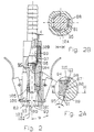
- Figure 2 shows a valve actuator in a universal clip-on valve connector with the housing 104 and with a sealing means comprising a first annular portion 82 and a second annular sealing portion 83 situated coaxially with the center axis 86 of the coupling section, in the direction of the center axis 86 of the coupling section 103.
- the first annular sealing portion 82 is closer to the opening 102 of the coupling section than the second annular sealing portion 83, and the diameter of the first annular sealing portion 82 is larger than the diameter of the second annular sealing portion 83.
- a taper cone 101 near the sealing surface 82 helps center the valve.
- the taper cone has an angle ⁇ with the center axis 86, and normally this angle is > 45°.
- a seperate cylinder sleeve 96 with cylinder wall portion 109 is shown which is sealed. It is fastened by for example a snap-lock 97 in the wall of the housing 104. This is an economical way of making the negative slip angle of the inclined enlargement wall portion 112 possible.
- the cylinder sleeve 96 has distant from the piston stop 95 an angle , so that the piston ring 108 is non-sealing there
- Figure 2A shows the channel portions 80 and 81 respectively defined by the enlargement wall portions 87 and 88 of the piston control means, respectively.
- the activating pin is streamlined with the piston 84 and the piston rod 85.
- the wall portion 87 has an angle ⁇ with the center axis 86 seen in the direction of the medium coming from the pressure source, which is larger than 0° and smaller than 20° (usually in the interval between 6° and 12°) .
- the stepped surface 98 of wall of housing 104 makes an air tight connection from the wall of the cylinder sleeve 96 to the cylinder 99. It is of course also possible to make the air tight connection on the other side of the cylinder.
- In the bottom of the cylinder sleeve 96 is the inclined enlargement wall portion 112 shown which together with the piston ring 115 forms channel portion 71.
- Figure 23 shows section H-H of figure 2A and the stopper 95 for the movement of the activating pin. Also shown is the wall portion 88 and the channel portion 81.
- Figure 3 shows an activating pin which is comparable of the one from Figure 1.
- the piston 129 is also shown.
- the piston rod 131 need not to be sealed against the piston control,
- the cylinder 136 of the valve actuator is within housing 132 of the valve connector.
- the coupling section 130 is also shown.
- Figure 3A shows a channel portion 133 with an expansion 135 and a channel portion 134 formed as a radial drilling 134.
- the piston ring 139 opens and closes this conducting channel at its orifice 137, depending on the position of the activating pin.
- the direction of the channel portion 134 in relation to the center axis is comparable with the angle T of channel portion 71 of Fig. 1A.
- the wall of expansion 135 has an angle comparable to angle ⁇ of the wall 76a Fig. 1A.
- the cylinder wall portion 138 of the cylinder 136 is also shown.
- Figure 4 shows an activating pin and its cylinder, which was shown in Figure 1. This is built in an assembled pipeline housing means 120,121 or the like, in which a valve 122 with a spring-force operated core pin 123 is situated, e.g. a Schrader valve. The activating pin is engaging with the core pin 123 of the valve.
- a valve 122 with a spring-force operated core pin 123 is situated, e.g. a Schrader valve.
- the activating pin is engaging with the core pin 123 of the valve.
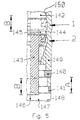
- Figure 5 shows a valve actuator in a universal valve connector. It is comparable with the one of Figure 1. However, two sealing means 140, 141 with an in-between distance A can seal two valves of different sizes. Two enlargements 1 and 2 of the diameter of the cylinder 142 in the cylinder wall 150 are shown, with the in-between distance B. An activating pin 143 is also shown, with two engaging levels on a distance B. The in-between distances can be equal or different if for example the valves are of a different type, so that the distance from the core pin to the sealing is not the same. Between the two enlargements 1 and 2 is a cylindrical wall portion 144, with cylinder portion 145, which fits the piston ring 108. Also is shown the center axis 146, the coupling section 147 and its opening 148 from the housing 149.
Landscapes
- Engineering & Computer Science (AREA)
- General Engineering & Computer Science (AREA)
- Mechanical Engineering (AREA)
- Fluid-Driven Valves (AREA)
- Lift Valve (AREA)
- Actuator (AREA)
- Check Valves (AREA)
- Mechanically-Actuated Valves (AREA)
- Quick-Acting Or Multi-Walled Pipe Joints (AREA)
Applications Claiming Priority (3)
| Application Number | Priority Date | Filing Date | Title |
|---|---|---|---|
| DK9700436 | 1997-11-19 | ||
| DK43697 | 1997-11-19 | ||
| PCT/DK1998/000507 WO1999026002A1 (en) | 1997-11-19 | 1998-11-19 | Valve actuator |
Publications (2)
| Publication Number | Publication Date |
|---|---|
| EP1032783A1 EP1032783A1 (en) | 2000-09-06 |
| EP1032783B1 true EP1032783B1 (en) | 2003-06-04 |
Family
ID=8156287
Family Applications (1)
| Application Number | Title | Priority Date | Filing Date |
|---|---|---|---|
| EP98958211A Expired - Lifetime EP1032783B1 (en) | 1997-11-19 | 1998-11-19 | Valve actuator |
Country Status (26)
| Country | Link |
|---|---|
| US (1) | US6401744B1 (da) |
| EP (1) | EP1032783B1 (da) |
| JP (1) | JP2001523803A (da) |
| KR (1) | KR100940328B1 (da) |
| CN (1) | CN1112531C (da) |
| AP (1) | AP2000001838A0 (da) |
| AT (1) | ATE242445T1 (da) |
| AU (1) | AU760890B2 (da) |
| BR (1) | BR9815286A (da) |
| CA (1) | CA2310371A1 (da) |
| DE (1) | DE69815382T2 (da) |
| DK (1) | DK1032783T3 (da) |
| EA (1) | EA001847B1 (da) |
| ES (1) | ES2202912T3 (da) |
| HU (1) | HUP0100720A3 (da) |
| IL (1) | IL136240A0 (da) |
| MX (1) | MXPA00004945A (da) |
| NO (1) | NO323430B1 (da) |
| NZ (1) | NZ505234A (da) |
| OA (1) | OA11412A (da) |
| PL (2) | PL188865B1 (da) |
| PT (1) | PT1032783E (da) |
| SK (1) | SK7252000A3 (da) |
| TW (1) | TW449651B (da) |
| UA (1) | UA66822C2 (da) |
| WO (1) | WO1999026002A1 (da) |
Families Citing this family (17)
| Publication number | Priority date | Publication date | Assignee | Title |
|---|---|---|---|---|
| HUP9900497A3 (en) * | 1995-02-03 | 2001-03-28 | Nvb International | Valve connector |
| DE19962038A1 (de) * | 1999-12-22 | 2001-08-09 | Aeroquip Vickers Internat Gmbh | Verbindungselement |
| DE29922948U1 (de) * | 1999-12-29 | 2000-06-29 | Alusuisse Bayrisches Druckguß-Werk GmbH & Co. KG, 85570 Markt Schwaben | Verbindungselement |
| CN101172480B (zh) * | 2006-10-30 | 2010-04-07 | 黄英哲 | 气嘴装置 |
| KR101517345B1 (ko) * | 2008-09-08 | 2015-05-04 | 삼성전자 주식회사 | 가스 주입기 |
| TW201207237A (en) * | 2010-08-03 | 2012-02-16 | Shu-Mu Wu | Air pump head |
| TW201235565A (en) | 2011-02-25 | 2012-09-01 | Nvb Composites Internat Uk Ltd | Piston-chamber combination vanderblom motor |
| PH12014500264A1 (en) | 2011-07-01 | 2014-03-17 | Nvb Composites Int Uk Ltd | Piston-chamber combination-vanderblom motor |
| CN105003420B (zh) * | 2014-04-21 | 2017-03-15 | 双馀实业有限公司 | 无扳手的打气筒气嘴 |
| TWI585296B (zh) * | 2015-08-12 | 2017-06-01 | 雙餘實業有限公司 | Double gas nozzle inflatable joints |
| GB2551965B (en) * | 2016-06-28 | 2019-01-30 | Lung Kuo Hsu | Joint structure for connecting an air valve |
| JP2021514902A (ja) * | 2018-02-26 | 2021-06-17 | クレンペル、ベンジャミン・ジェイ | ポンプ機構インサート |
| CN111828760A (zh) * | 2020-07-24 | 2020-10-27 | 格力电器(武汉)有限公司 | 母接头 |
| AU2020267180B1 (en) * | 2020-11-10 | 2021-06-24 | Gurtech (Pty) Ltd | An air chuck |
| USD969876S1 (en) | 2020-12-11 | 2022-11-15 | Milwaukee Electric Tool Corporation | Inflator |
| RU209967U1 (ru) * | 2021-12-15 | 2022-03-24 | Общество с ограниченной ответственностью Управляющая компания "Алтайский завод прецизионных изделий" | Клапан сброса остаточного давления |
| US20240308479A1 (en) * | 2023-03-19 | 2024-09-19 | John Anderson | Tire Inflation Assembly |
Family Cites Families (11)
| Publication number | Priority date | Publication date | Assignee | Title |
|---|---|---|---|---|
| US2489397A (en) * | 1944-05-05 | 1949-11-29 | Brummer Henry | Tire valve operating device |
| US2685906A (en) * | 1952-01-19 | 1954-08-10 | Scovill Manufacturing Co | Running inflation and deflation system |
| GB872246A (en) * | 1956-08-03 | 1961-07-05 | Walters & Dobson Ltd | Improvements in or relating to tyre valve connectors |
| US2976906A (en) * | 1958-09-10 | 1961-03-28 | Wunibald I E Kamm | Tire pressure control device |
| GB977139A (en) * | 1962-10-15 | 1964-12-02 | Walters & Dobson Ltd | Improvements in or relating to tyre valve connectors |
| US3249144A (en) * | 1964-09-23 | 1966-05-03 | Berg Mfg & Sales Co | Tire pressure system and valve |
| DE2544555A1 (de) * | 1975-10-04 | 1977-04-07 | Magirus Deutz Ag | Vorrichtung zur steuerung des luftdruckes im reifen eines fahrzeuges |
| US4932451A (en) * | 1989-01-26 | 1990-06-12 | General Motors Corporation | Vehicle wheel end assembly with air passage |
| US4938272A (en) * | 1989-01-26 | 1990-07-03 | General Motors Corporation | Valve actuator for tire pressure management |
| US5094263A (en) * | 1991-08-02 | 1992-03-10 | General Motors Corporation | Tire pressure management actuator with bypass leakage prevention |
| HUP9900497A3 (en) * | 1995-02-03 | 2001-03-28 | Nvb International | Valve connector |
-
1998
- 1998-11-19 WO PCT/DK1998/000507 patent/WO1999026002A1/en not_active Ceased
- 1998-11-19 AT AT98958211T patent/ATE242445T1/de active
- 1998-11-19 US US09/554,859 patent/US6401744B1/en not_active Expired - Fee Related
- 1998-11-19 KR KR1020007005477A patent/KR100940328B1/ko not_active Expired - Fee Related
- 1998-11-19 NZ NZ505234A patent/NZ505234A/xx unknown
- 1998-11-19 HU HU0100720A patent/HUP0100720A3/hu unknown
- 1998-11-19 PL PL98340537A patent/PL188865B1/pl not_active IP Right Cessation
- 1998-11-19 EA EA200000540A patent/EA001847B1/ru not_active IP Right Cessation
- 1998-11-19 ES ES98958211T patent/ES2202912T3/es not_active Expired - Lifetime
- 1998-11-19 PT PT98958211T patent/PT1032783E/pt unknown
- 1998-11-19 CA CA002310371A patent/CA2310371A1/en not_active Abandoned
- 1998-11-19 PL PL98368771A patent/PL189386B1/pl not_active IP Right Cessation
- 1998-11-19 DK DK98958211T patent/DK1032783T3/da active
- 1998-11-19 AU AU14336/99A patent/AU760890B2/en not_active Ceased
- 1998-11-19 BR BR9815286-6A patent/BR9815286A/pt not_active IP Right Cessation
- 1998-11-19 CN CN98811351A patent/CN1112531C/zh not_active Expired - Fee Related
- 1998-11-19 JP JP2000521334A patent/JP2001523803A/ja active Pending
- 1998-11-19 AP APAP/P/2000/001838A patent/AP2000001838A0/en unknown
- 1998-11-19 UA UA2000063541A patent/UA66822C2/uk unknown
- 1998-11-19 EP EP98958211A patent/EP1032783B1/en not_active Expired - Lifetime
- 1998-11-19 MX MXPA00004945A patent/MXPA00004945A/es not_active IP Right Cessation
- 1998-11-19 DE DE69815382T patent/DE69815382T2/de not_active Expired - Lifetime
- 1998-11-19 SK SK725-2000A patent/SK7252000A3/sk unknown
- 1998-11-19 IL IL13624098A patent/IL136240A0/xx unknown
-
1999
- 1999-07-06 TW TW088111436A patent/TW449651B/zh not_active IP Right Cessation
-
2000
- 2000-05-17 OA OA1200000147A patent/OA11412A/en unknown
- 2000-05-19 NO NO20002606A patent/NO323430B1/no not_active IP Right Cessation
Also Published As
Similar Documents
| Publication | Publication Date | Title |
|---|---|---|
| EP1032783B1 (en) | Valve actuator | |
| US7946630B2 (en) | Hydraulic system | |
| US8770361B2 (en) | Residual pressure holding valve and suspension strut | |
| US5096029A (en) | Longitudinally controllable adjustment device | |
| US5826613A (en) | Flow control valve | |
| JPH05502645A (ja) | アンチロック付流体圧ブレーキ装置用マスタブレーキシリンダ | |
| JP4568772B2 (ja) | 流体作動式バルブアッセンブリ | |
| US20050028865A1 (en) | Rapid access tire valve for a pneumatic tire on a rim of a vehicle and connector therefor | |
| US5868160A (en) | Two-way insert valve | |
| EP0462848A2 (en) | Fluid pressure actuator | |
| EA000511B1 (ru) | Активирующий штифт | |
| CN210566457U (zh) | 一种单向阀 | |
| JP2004536744A5 (da) | ||
| KR101198875B1 (ko) | 유압 시스템 | |
| EP0285255A1 (en) | Master Cylinder | |
| EP2040968B1 (en) | High flow calibration test point | |
| WO2007136274A1 (en) | Valve | |
| CZ20001785A3 (cs) | Ovladač ventilku | |
| HK1034306B (en) | Valve actuator | |
| RU21431U1 (ru) | Шаровой кран | |
| JPH03503872A (ja) | ベント制御式バイパス付圧力平衡式比例弁 | |
| KR930000504B1 (ko) | 배관의 자동 착탈 장치용 커플링 | |
| IL104717A (en) | In-line fluid control valve | |
| KR20000001354U (ko) | 고압 호스 연결장치 | |
| KR20180113061A (ko) | 공압을 이용한 컨트롤 밸브 |
Legal Events
| Date | Code | Title | Description |
|---|---|---|---|
| PUAI | Public reference made under article 153(3) epc to a published international application that has entered the european phase |
Free format text: ORIGINAL CODE: 0009012 |
|
| 17P | Request for examination filed |
Effective date: 20000619 |
|
| AK | Designated contracting states |
Kind code of ref document: A1 Designated state(s): AT BE CH CY DE DK ES FI FR GB GR IE IT LI LU MC NL PT SE |
|
| AX | Request for extension of the european patent |
Free format text: AL PAYMENT 20000619;LT PAYMENT 20000619;LV PAYMENT 20000619;MK PAYMENT 20000619;RO PAYMENT 20000619;SI PAYMENT 20000619 |
|
| GRAH | Despatch of communication of intention to grant a patent |
Free format text: ORIGINAL CODE: EPIDOS IGRA |
|
| GRAH | Despatch of communication of intention to grant a patent |
Free format text: ORIGINAL CODE: EPIDOS IGRA |
|
| GRAA | (expected) grant |
Free format text: ORIGINAL CODE: 0009210 |
|
| AK | Designated contracting states |
Designated state(s): AT BE CH CY DE DK ES FI FR GB GR IE IT LI LU MC NL PT SE |
|
| AX | Request for extension of the european patent |
Extension state: AL LT LV MK RO SI |
|
| REG | Reference to a national code |
Ref country code: GB Ref legal event code: FG4D |
|
| REG | Reference to a national code |
Ref country code: CH Ref legal event code: EP |
|
| REG | Reference to a national code |
Ref country code: IE Ref legal event code: FG4D |
|
| REF | Corresponds to: |
Ref document number: 69815382 Country of ref document: DE Date of ref document: 20030710 Kind code of ref document: P |
|
| REG | Reference to a national code |
Ref country code: SE Ref legal event code: TRGR |
|
| REG | Reference to a national code |
Ref country code: DK Ref legal event code: T3 |
|
| REG | Reference to a national code |
Ref country code: GR Ref legal event code: EP Ref document number: 20030403602 Country of ref document: GR |
|
| PG25 | Lapsed in a contracting state [announced via postgrant information from national office to epo] |
Ref country code: CY Free format text: LAPSE BECAUSE OF FAILURE TO SUBMIT A TRANSLATION OF THE DESCRIPTION OR TO PAY THE FEE WITHIN THE PRESCRIBED TIME-LIMIT Effective date: 20031119 |
|
| LTIE | Lt: invalidation of european patent or patent extension |
Effective date: 20030604 |
|
| REG | Reference to a national code |
Ref country code: CH Ref legal event code: NV Representative=s name: WALDER WYSS & PARTNER RECHTSANWAELTE |
|
| REG | Reference to a national code |
Ref country code: ES Ref legal event code: FG2A Ref document number: 2202912 Country of ref document: ES Kind code of ref document: T3 |
|
| PLBE | No opposition filed within time limit |
Free format text: ORIGINAL CODE: 0009261 |
|
| STAA | Information on the status of an ep patent application or granted ep patent |
Free format text: STATUS: NO OPPOSITION FILED WITHIN TIME LIMIT |
|
| ET | Fr: translation filed | ||
| 26N | No opposition filed |
Effective date: 20040305 |
|
| EUG | Se: european patent has lapsed | ||
| PG25 | Lapsed in a contracting state [announced via postgrant information from national office to epo] |
Ref country code: IE Free format text: LAPSE BECAUSE OF NON-PAYMENT OF DUE FEES Effective date: 20041119 |
|
| REG | Reference to a national code |
Ref country code: IE Ref legal event code: MM4A |
|
| PG25 | Lapsed in a contracting state [announced via postgrant information from national office to epo] |
Ref country code: SE Free format text: LAPSE BECAUSE OF NON-PAYMENT OF DUE FEES Effective date: 20051120 |
|
| EUG | Se: european patent has lapsed | ||
| REG | Reference to a national code |
Ref country code: PT Ref legal event code: MM4A Effective date: 20060519 |
|
| REG | Reference to a national code |
Ref country code: CH Ref legal event code: NV Representative=s name: BUECHEL, VON REVY & PARTNER |
|
| REG | Reference to a national code |
Ref country code: PT Ref legal event code: NF4A Free format text: RESTITUTIO IN INTEGRUM Effective date: 20070801 |
|
| REG | Reference to a national code |
Ref country code: IE Ref legal event code: NE4A |
|
| REG | Reference to a national code |
Ref country code: PT Ref legal event code: MM4A Free format text: LAPSE DUE TO NON-PAYMENT OF FEES Effective date: 20080519 |
|
| REG | Reference to a national code |
Ref country code: PT Ref legal event code: NF4A Free format text: RESTITUTIO IN INTEGRUM Effective date: 20080603 |
|
| PGRI | Patent reinstated in contracting state [announced from national office to epo] |
Ref country code: SE Effective date: 20080715 |
|
| PGRI | Patent reinstated in contracting state [announced from national office to epo] |
Ref country code: PT Effective date: 20080603 |
|
| REG | Reference to a national code |
Ref country code: IE Ref legal event code: NF4A Effective date: 20081106 |
|
| PGRI | Patent reinstated in contracting state [announced from national office to epo] |
Ref country code: IE Effective date: 20081106 |
|
| REG | Reference to a national code |
Ref country code: PT Ref legal event code: MM4A Free format text: LAPSE DUE TO NON-PAYMENT OF FEES Effective date: 20100519 |
|
| PG25 | Lapsed in a contracting state [announced via postgrant information from national office to epo] |
Ref country code: PT Free format text: LAPSE BECAUSE OF NON-PAYMENT OF DUE FEES Effective date: 20100519 |
|
| PGFP | Annual fee paid to national office [announced via postgrant information from national office to epo] |
Ref country code: DK Payment date: 20100531 Year of fee payment: 12 |
|
| PGFP | Annual fee paid to national office [announced via postgrant information from national office to epo] |
Ref country code: BE Payment date: 20100531 Year of fee payment: 12 |
|
| PGFP | Annual fee paid to national office [announced via postgrant information from national office to epo] |
Ref country code: FI Payment date: 20100730 Year of fee payment: 12 |
|
| REG | Reference to a national code |
Ref country code: PT Ref legal event code: NF4A Free format text: RESTITUTIO IN INTEGRUM Effective date: 20101129 |
|
| REG | Reference to a national code |
Ref country code: PT Ref legal event code: NF4A Free format text: RESTITUTIO IN INTEGRUM Effective date: 20101203 |
|
| PGFP | Annual fee paid to national office [announced via postgrant information from national office to epo] |
Ref country code: GR Payment date: 20100531 Year of fee payment: 12 |
|
| PGRI | Patent reinstated in contracting state [announced from national office to epo] |
Ref country code: PT Effective date: 20101203 |
|
| BERE | Be: lapsed |
Owner name: *NVB INTERNATIONAL A/S Effective date: 20101130 |
|
| REG | Reference to a national code |
Ref country code: DK Ref legal event code: EBP |
|
| PG25 | Lapsed in a contracting state [announced via postgrant information from national office to epo] |
Ref country code: GR Free format text: LAPSE BECAUSE OF NON-PAYMENT OF DUE FEES Effective date: 20110602 |
|
| PGFP | Annual fee paid to national office [announced via postgrant information from national office to epo] |
Ref country code: MC Payment date: 20110531 Year of fee payment: 13 Ref country code: LU Payment date: 20110601 Year of fee payment: 13 Ref country code: CH Payment date: 20110531 Year of fee payment: 13 |
|
| PG25 | Lapsed in a contracting state [announced via postgrant information from national office to epo] |
Ref country code: FI Free format text: LAPSE BECAUSE OF NON-PAYMENT OF DUE FEES Effective date: 20101119 Ref country code: BE Free format text: LAPSE BECAUSE OF NON-PAYMENT OF DUE FEES Effective date: 20101130 |
|
| PG25 | Lapsed in a contracting state [announced via postgrant information from national office to epo] |
Ref country code: DK Free format text: LAPSE BECAUSE OF NON-PAYMENT OF DUE FEES Effective date: 20101130 |
|
| REG | Reference to a national code |
Ref country code: PT Ref legal event code: NF4A Free format text: RESTITUTIO IN INTEGRUM Effective date: 20120521 |
|
| PG25 | Lapsed in a contracting state [announced via postgrant information from national office to epo] |
Ref country code: MC Free format text: LAPSE BECAUSE OF NON-PAYMENT OF DUE FEES Effective date: 20111130 |
|
| REG | Reference to a national code |
Ref country code: CH Ref legal event code: PL |
|
| PG25 | Lapsed in a contracting state [announced via postgrant information from national office to epo] |
Ref country code: CH Free format text: LAPSE BECAUSE OF NON-PAYMENT OF DUE FEES Effective date: 20111130 Ref country code: LI Free format text: LAPSE BECAUSE OF NON-PAYMENT OF DUE FEES Effective date: 20111130 |
|
| PGFP | Annual fee paid to national office [announced via postgrant information from national office to epo] |
Ref country code: NL Payment date: 20120605 Year of fee payment: 14 Ref country code: IE Payment date: 20120531 Year of fee payment: 14 Ref country code: DE Payment date: 20120530 Year of fee payment: 14 |
|
| REG | Reference to a national code |
Ref country code: CH Ref legal event code: AEN Free format text: DAS PATENT IST AUFGRUND DES WEITERBEHANDLUNGSANTRAGS VOM 06.08.2012 REAKTIVIERT WORDEN. |
|
| PG25 | Lapsed in a contracting state [announced via postgrant information from national office to epo] |
Ref country code: PT Free format text: LAPSE BECAUSE OF NON-PAYMENT OF DUE FEES Effective date: 20120521 |
|
| PGFP | Annual fee paid to national office [announced via postgrant information from national office to epo] |
Ref country code: FR Payment date: 20120619 Year of fee payment: 14 Ref country code: SE Payment date: 20120530 Year of fee payment: 14 Ref country code: GB Payment date: 20120531 Year of fee payment: 14 |
|
| PGRI | Patent reinstated in contracting state [announced from national office to epo] |
Ref country code: CH Effective date: 20120808 Ref country code: LI Effective date: 20120808 |
|
| PGFP | Annual fee paid to national office [announced via postgrant information from national office to epo] |
Ref country code: ES Payment date: 20120530 Year of fee payment: 14 |
|
| PGFP | Annual fee paid to national office [announced via postgrant information from national office to epo] |
Ref country code: PT Payment date: 20120521 Year of fee payment: 14 |
|
| PGFP | Annual fee paid to national office [announced via postgrant information from national office to epo] |
Ref country code: AT Payment date: 20120530 Year of fee payment: 14 |
|
| REG | Reference to a national code |
Ref country code: PT Ref legal event code: MM4A Free format text: LAPSE DUE TO NON-PAYMENT OF FEES Effective date: 20130520 |
|
| PG25 | Lapsed in a contracting state [announced via postgrant information from national office to epo] |
Ref country code: LU Free format text: LAPSE BECAUSE OF NON-PAYMENT OF DUE FEES Effective date: 20111119 |
|
| REG | Reference to a national code |
Ref country code: NL Ref legal event code: V1 Effective date: 20130601 |
|
| REG | Reference to a national code |
Ref country code: CH Ref legal event code: PL |
|
| REG | Reference to a national code |
Ref country code: AT Ref legal event code: MM01 Ref document number: 242445 Country of ref document: AT Kind code of ref document: T Effective date: 20121119 |
|
| GBPC | Gb: european patent ceased through non-payment of renewal fee |
Effective date: 20121119 |
|
| PG25 | Lapsed in a contracting state [announced via postgrant information from national office to epo] |
Ref country code: SE Free format text: LAPSE BECAUSE OF NON-PAYMENT OF DUE FEES Effective date: 20121120 Ref country code: LI Free format text: LAPSE BECAUSE OF NON-PAYMENT OF DUE FEES Effective date: 20121130 Ref country code: CH Free format text: LAPSE BECAUSE OF NON-PAYMENT OF DUE FEES Effective date: 20121130 Ref country code: AT Free format text: LAPSE BECAUSE OF NON-PAYMENT OF DUE FEES Effective date: 20121119 |
|
| REG | Reference to a national code |
Ref country code: NL Ref legal event code: RD1H Effective date: 20130808 Ref country code: IE Ref legal event code: MM4A |
|
| REG | Reference to a national code |
Ref country code: FR Ref legal event code: ST Effective date: 20130731 |
|
| PG25 | Lapsed in a contracting state [announced via postgrant information from national office to epo] |
Ref country code: PT Free format text: LAPSE BECAUSE OF NON-PAYMENT OF DUE FEES Effective date: 20130520 Ref country code: NL Free format text: LAPSE BECAUSE OF NON-PAYMENT OF DUE FEES Effective date: 20130601 |
|
| PGFP | Annual fee paid to national office [announced via postgrant information from national office to epo] |
Ref country code: IT Payment date: 20130530 Year of fee payment: 15 |
|
| REG | Reference to a national code |
Ref country code: DE Ref legal event code: R119 Ref document number: 69815382 Country of ref document: DE Effective date: 20130601 |
|
| PG25 | Lapsed in a contracting state [announced via postgrant information from national office to epo] |
Ref country code: DE Free format text: LAPSE BECAUSE OF NON-PAYMENT OF DUE FEES Effective date: 20130601 Ref country code: IE Free format text: LAPSE BECAUSE OF NON-PAYMENT OF DUE FEES Effective date: 20121119 |
|
| PG25 | Lapsed in a contracting state [announced via postgrant information from national office to epo] |
Ref country code: FR Free format text: LAPSE BECAUSE OF NON-PAYMENT OF DUE FEES Effective date: 20121130 Ref country code: GB Free format text: LAPSE BECAUSE OF NON-PAYMENT OF DUE FEES Effective date: 20121119 |
|
| REG | Reference to a national code |
Ref country code: NL Ref legal event code: RD2H Effective date: 20140130 |
|
| REG | Reference to a national code |
Ref country code: ES Ref legal event code: FD2A Effective date: 20140305 |
|
| REG | Reference to a national code |
Ref country code: FR Ref legal event code: RN Effective date: 20140204 |
|
| REG | Reference to a national code |
Ref country code: FR Ref legal event code: IC Effective date: 20140318 |
|
| PG25 | Lapsed in a contracting state [announced via postgrant information from national office to epo] |
Ref country code: ES Free format text: LAPSE BECAUSE OF NON-PAYMENT OF DUE FEES Effective date: 20121120 |
|
| REG | Reference to a national code |
Ref country code: NL Ref legal event code: V1 Effective date: 20130601 |
|
| PG25 | Lapsed in a contracting state [announced via postgrant information from national office to epo] |
Ref country code: IT Free format text: LAPSE BECAUSE OF NON-PAYMENT OF DUE FEES Effective date: 20131119 |
|
| REG | Reference to a national code |
Ref country code: SE Ref legal event code: EUG |