EP1032231A2 - Nahtloses Zweiwegekommunikationssystem langs Strassen - Google Patents
Nahtloses Zweiwegekommunikationssystem langs Strassen Download PDFInfo
- Publication number
- EP1032231A2 EP1032231A2 EP00301348A EP00301348A EP1032231A2 EP 1032231 A2 EP1032231 A2 EP 1032231A2 EP 00301348 A EP00301348 A EP 00301348A EP 00301348 A EP00301348 A EP 00301348A EP 1032231 A2 EP1032231 A2 EP 1032231A2
- Authority
- EP
- European Patent Office
- Prior art keywords
- stationary
- predetermined
- unit
- data
- mobile unit
- Prior art date
- Legal status (The legal status is an assumption and is not a legal conclusion. Google has not performed a legal analysis and makes no representation as to the accuracy of the status listed.)
- Withdrawn
Links
- 238000004891 communication Methods 0.000 title claims abstract description 65
- 238000000034 method Methods 0.000 claims abstract description 57
- 230000005540 biological transmission Effects 0.000 claims description 153
- 238000001514 detection method Methods 0.000 claims description 22
- 239000003550 marker Substances 0.000 claims description 16
- 230000010363 phase shift Effects 0.000 claims description 6
- 239000013307 optical fiber Substances 0.000 claims description 5
- 230000008707 rearrangement Effects 0.000 claims 2
- 230000008054 signal transmission Effects 0.000 claims 1
- 238000010586 diagram Methods 0.000 description 20
- 230000009466 transformation Effects 0.000 description 17
- 230000006870 function Effects 0.000 description 13
- 238000012937 correction Methods 0.000 description 12
- 230000008569 process Effects 0.000 description 10
- 238000005562 fading Methods 0.000 description 7
- 230000000694 effects Effects 0.000 description 6
- 230000008859 change Effects 0.000 description 5
- 238000009826 distribution Methods 0.000 description 5
- 238000011156 evaluation Methods 0.000 description 5
- 230000003287 optical effect Effects 0.000 description 4
- 230000009977 dual effect Effects 0.000 description 3
- 230000006872 improvement Effects 0.000 description 3
- 230000004044 response Effects 0.000 description 3
- 239000004065 semiconductor Substances 0.000 description 3
- 230000007704 transition Effects 0.000 description 3
- 238000013461 design Methods 0.000 description 2
- 239000007787 solid Substances 0.000 description 2
- 238000001228 spectrum Methods 0.000 description 2
- 238000013459 approach Methods 0.000 description 1
- 238000004364 calculation method Methods 0.000 description 1
- 239000000969 carrier Substances 0.000 description 1
- 230000006835 compression Effects 0.000 description 1
- 238000007906 compression Methods 0.000 description 1
- 238000010276 construction Methods 0.000 description 1
- 125000004122 cyclic group Chemical group 0.000 description 1
- 239000000835 fiber Substances 0.000 description 1
- 238000005259 measurement Methods 0.000 description 1
- 238000010295 mobile communication Methods 0.000 description 1
- 230000001360 synchronised effect Effects 0.000 description 1
Images


Classifications
-
- H—ELECTRICITY
- H04—ELECTRIC COMMUNICATION TECHNIQUE
- H04W—WIRELESS COMMUNICATION NETWORKS
- H04W16/00—Network planning, e.g. coverage or traffic planning tools; Network deployment, e.g. resource partitioning or cells structures
- H04W16/24—Cell structures
-
- G—PHYSICS
- G08—SIGNALLING
- G08G—TRAFFIC CONTROL SYSTEMS
- G08G1/00—Traffic control systems for road vehicles
- G08G1/09—Arrangements for giving variable traffic instructions
- G08G1/091—Traffic information broadcasting
- G08G1/093—Data selection, e.g. prioritizing information, managing message queues, selecting the information to be output
-
- G—PHYSICS
- G08—SIGNALLING
- G08G—TRAFFIC CONTROL SYSTEMS
- G08G1/00—Traffic control systems for road vehicles
- G08G1/09—Arrangements for giving variable traffic instructions
- G08G1/091—Traffic information broadcasting
- G08G1/094—Hardware aspects; Signal processing or signal properties, e.g. frequency bands
-
- H—ELECTRICITY
- H04—ELECTRIC COMMUNICATION TECHNIQUE
- H04B—TRANSMISSION
- H04B7/00—Radio transmission systems, i.e. using radiation field
- H04B7/24—Radio transmission systems, i.e. using radiation field for communication between two or more posts
- H04B7/26—Radio transmission systems, i.e. using radiation field for communication between two or more posts at least one of which is mobile
- H04B7/2625—Radio transmission systems, i.e. using radiation field for communication between two or more posts at least one of which is mobile using common wave
-
- H—ELECTRICITY
- H04—ELECTRIC COMMUNICATION TECHNIQUE
- H04L—TRANSMISSION OF DIGITAL INFORMATION, e.g. TELEGRAPHIC COMMUNICATION
- H04L1/00—Arrangements for detecting or preventing errors in the information received
- H04L1/004—Arrangements for detecting or preventing errors in the information received by using forward error control
- H04L1/0056—Systems characterized by the type of code used
- H04L1/0071—Use of interleaving
-
- H—ELECTRICITY
- H04—ELECTRIC COMMUNICATION TECHNIQUE
- H04L—TRANSMISSION OF DIGITAL INFORMATION, e.g. TELEGRAPHIC COMMUNICATION
- H04L5/00—Arrangements affording multiple use of the transmission path
- H04L5/02—Channels characterised by the type of signal
- H04L5/023—Multiplexing of multicarrier modulation signals, e.g. multi-user orthogonal frequency division multiple access [OFDMA]
Definitions
- the current invention is generally related to a two-way communication system between a mobile unit and a stationary unit, and more particularly related to a two-way communication system between a car and information stations located along a road.
- a road communication system enables a ground vehicle such as a car to communicate with a traffic control or a road administration for disseminating or collecting information on traffic or road conditions.
- the information is gathered by stationary units along the road and is also collected by various sensors on a car.
- the information exchange is designed to help drivers avoid accidents as well as to automatically navigate the car without human intervention.
- One example of the above described road communication system is disclosed in Japanese Patent Laid Publication Hei8-241495.
- To implement the road communication system it is necessary to place a continuous array of communication cells or stationary units along the roads.
- a leaking coaxial cable may be placed along the roads, not only the construction is significant, but also the radio signal travels only a short distance in a cross direction due to the low position of the cable.
- antennas are placed at a predetermined interval along the roads to communicate with cars. Each antenna covers a predetermined relatively wide transmission area or cell.
- Each antenna may be connected to a base unit of a road administrator via optical fibers.
- the above system is advantageous for communication between stationary units, the above system may not be advantageous for the road communication system.
- the road communication system includes a mobile unit such as one used in a car which moves at a high speed and passes a number of cells over a short period time, it is necessary for a car to be equipped with a device for switching reception frequencies at a high speed. Consequently, a mobile unit needs a high-speed oscillator or a plurality of oscillators. The required additional hardware is either costly or takes physical space.
- Japanese Patent Laid Publication Hei 9-358581 discloses ways to provide a stable signal containing the same data while a car moves across cells. In other words, the identical information is transmitted from every stationary unit.
- a method of transmitting information via a common frequency carrier between a mobile unit and a set of stationary units including: transmitting first data on a predetermined first subcarrier and second data on a predetermined second subcarrier between a first stationary unit and the mobile unit for communication within a predetermined first transmission area; transmitting third data on the predetermined first subcarrier and the second data on the predetermined second subcarrier between a second stationary unit and the mobile unit for communication within a predetermined second transmission area, the second stationary unit being located near the first stationary unit, the predetermined first transmission area and the predetermined second transmission area being partially overlapping; and maintaining communication among the mobile unit, the first stationary unit and the second stationary unit while the mobile unit is moving from the predetermined first transmission area to the predetermined second transmission area.
- a method of transmitting information via a common frequency carrier between a mobile unit and a set of stationary units including: transmitting an information signal which is modulated by orthogonal frequency division multiplex modulation between a first stationary unit and the mobile unit for communication within a predetermined first transmission area; transmitting the information signal which is modulated by the orthogonal frequency division multiplex modulation between a second stationary unit and the mobile unit for communication within a predetermined second transmission area, the second stationary unit being located near the first stationary unit, the predetermined first transmission area and the predetermined second transmission area being partially overlapping; and maintaining communication among the mobile unit, the first stationary unit and the second stationary unit while the mobile unit is moving from the predetermined first transmission area to the predetermined transmission second area.
- a system for transmitting information via a common frequency carrier between a mobile unit and a set of stationary units including: a first stationary unit for transmitting first data on a predetermined first subcarrier and second data on a predetermined second subcarrier within a predetermined first transmission area; a second stationary unit located near the first stationary unit for transmitting third data on the predetermined first subcarrier and the second data on the predetermined second subcarrier within a predetermined second transmission area, the predetermined first transmission area and the predetermined second transmission area being partially overlapping; and a mobile unit for maintaining communication among the mobile unit, the first stationary unit and the second stationary unit while the mobile unit is moving from the predetermined first transmission area to the predetermined second transmission area.
- a system for transmitting information via a common frequency carrier between a mobile unit and a set of stationary units including: a first stationary unit for transmitting an information signal which is modulated by orthogonal frequency division multiplex modulation within a predetermined first transmission area; a second stationary unit for transmitting the information signal which is modulated by the orthogonal frequency division multiplex modulation within a predetermined second transmission area;, the predetermined first transmission area and the predetermined second transmission area being partially overlapping; and a mobile unit for maintaining communication among the mobile unit, the first stationary unit and the second stationary unit while the mobile unit is moving from the predetermined first transmission area to the predetermined transmission area.
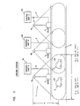
- FIG. 1 a block diagram illustrates one preferred embodiment of the road communication system according to the current invention.
- the preferred embodiment generally includes at least two ground stations or stationary units 1 and a mobile unit or car 2. As the car 2 travels along the road near the stationary units 1 as shown at positions 2A and 2B, there is constant communication between the car 2 and at least one of the stationary units 1. The content of the information or data possibly changes as the car 2 receives the data from a different stationary unit 1.
- each stationary unit or cell 1 further includes a corresponding one of control units or control systems 6a-6c, a corresponding one of antennas 4a-4c and a coaxial cable 5.
- Each of the antennas 4a-4c has a predetermined transmission direction and a corresponding transmission area or cell area E where transmission reaches as indicated by dotted lines along a road way, and the adjacent transmission areas E are partially overlapping.
- each of the antennas 4a-4c has an approximate height of 10 meters, and the transmission area has a diameter or length r of about 100 meters along the roadway.
- the antennas 4a-4c transmit a radio signal at a common or single frequency within the above described transmission area E. For example, all of the antennas 4a-4c transmit 6 GHz signals.
- the car 2 receives the radio signal either from the front direction or from the rear direction.
- the car 2 receives the radio signal from approximately above when the car 2 is located below one of the antennas 4a-4c.
- the coaxial cable 5 connects one of the antennas 4a-4c to a corresponding one of the control units 6a-6c.
- Each of the coaxial cables 5 includes a pair of a up-cable and a down-cable for transmitting information between each of the antennas 4a-4c and the corresponding control unit 6a-6c in a predetermined direction.
- an optical fiber cable is used in lieu of the coaxial cable 5.
- a disclosure such as "Fiber/Radio For the Provision of Cordless/Mobile Elephony Services in The Access Network," Electron. Lett., Vol. 26, No. 24 (Nov. 1990) is hereby incorporated by external reference.
- Each of the control units 6a-6c outputs to the corresponding antennas 4a-4c via the coaxial cable 5 modulated signals including traffic data including traffic information ahead of the operators for facilitating the drive.
- the control units 6a-6c also receive from the car 2 information on a vehicle ID and road surface conditions. Sensors are mounted on the car 2 and collect the road surface conditions.
- the control units 6a-6c generate a predetermined radio signal containing the above described information such as (A,B), (C,B) or (C,D) and transmit the radio signal at a common frequency. Because of the common frequency signal, there is no need to change the frequency of an oscillator mounted on the car 2 as the car moves from one transmission area of the control unit 6a, 6b or 6c to that of another. Since the car 2 does not have to be equipped with an expensive and bulky oscillator for handling signals in multiple frequencies, the preferred embodiment can spare the additional cost and space for the oscillator in the car 2.
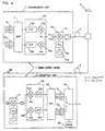
- the control system 6 includes a transmission unit 7 and a reception unit 9 and utilizes the orthogonal frequency division multiplex (OFDM) modulation technique which multiplexes a plurality of orthogonal frequency carriers for transmitting divided data.
- the transmission unit 7 generally includes an inverse Fourier function transformation (IFFT) circuit 71, a quadrature phase shift keying (QPSK) modulation circuit 73 and an up-converter 74.
- IFFT inverse Fourier function transformation
- QPSK quadrature phase shift keying
- up-converter 74 The IFFT circuit 71 performs the inverse Fourier transformation on each of parallel input signals S1 and S2 and serially translates the inversely transformed data back to serial data.
- the IFFT circuit 71 time compresses the serial data and determines a guard time by placing a rear symbol in a forward position.
- the IFFT circuit 71 outputs two signals to the QPSK circuit 73. One signal has either 0° or 180° phase, and the other signal has either 90° or 270° phase.
- the QPSK circuit 73 modulates output signals from the IFFT circuit 71 and the up-converter 74 generates a radio signal.
- the QPSK circuit 73 further includes a pair of digital-to-analog converters (D/A) 73a and 73b as well as a pair of multipliers 73c and 73d.
- the first D/A converter 73a outputs a signal to the multiplier 73c to multiply by a sine signal so as to produce an output signal having either 0° or 180° phase.
- the second D/A converter 73b outputs a signal to the multiplier 73d to multiply by a cosine signal so as to produce an output signal having either 90° or 270° phase.
- the multiplied signals are added before being outputted.
- the up-converter 74 converts the output signal from the QPSK circuit 73 to a radio frequency.
- the up-converter 74 includes a local oscillator 74a, a Phase Locked Loop (PLL) 74b and a multiplier 74c. It is desired that the precision of the local oscillator 74a be the same order as a quotient of a speed of a car divided by the radio signal speed in view of a Doppler effect caused by the moving car.
- a commercially available oscillator can sufficiently match the above required precision.
- the oscillator 74a outputs a signal to the PLL 74b, and the output of the PLL 74b is multiplied with the output signal from the up-converter 74 before being outputted from the control unit 6.
- the output signal from the up-converter 74 is inputted into the antenna 4 via the cable 5 and is transmitted as a radio signal from the antenna 4.
- the control system 6 additionally includes an error correction coding circuit, a differential coding circuit and an interleaving circuit for interleaving time and or frequency.
- circuits utilizing other modulation techniques such as quadrature amplitude modulation (QAM), binary phase shift keying (BPSK), and 8 phase shift keying (8PSK) are used in stead of the QPSK circuit 73.
- QAM quadrature amplitude modulation
- BPSK binary phase shift keying
- 8PSK 8 phase shift keying
- an optical fiber is used as the cable 5
- an electro-optical (E/0) converter is needed to convert the output electrical signal from the up-converter 74 into an optical signal before transmitting through the optical cable 5.
- An optic-electrical (O/E) converter is also needed to convert the optical signal back to an electrical signal before transmitted via the antenna 4.
- control system 6 for receiving data from a car.
- the components in the control unit 6 for receiving data from the car 2 are substantially similar to the ones in the car 2 as will be described with respect to FIGURE 4.
- the components for transmitting the data in the car 2 are also substantially similar to the ones in the control unit 6.
- a graph with a frequency axis f and a time axis t illustrates symbol transmissions based upon the orthogonal frequency division multiplex (OFDM) modulation technique.
- the length of a valid symbol is expressed by Ts while that of a guard time is expressed by ⁇ t.
- the time compression rate is expressed by (Ts + ⁇ t) / Ts .
- the guard time ⁇ t is set to be longer than an amount of delay time due to multiple pass transmission. Because of the longer guard time ⁇ t, it is possible to demodulate the received signal without any regard to a symbol overlap.
- the multiple pass delay time is determined either by measurements or calculations.
- the multiple pass delay time is expected to be approximately 500 nanoseconds.
- a delay circuit performs a delay detection step by multiplying a current signal and a signal that is one bit before the current signal if phase modulation techniques such as QPSK, BPSK and 8PSK are used.
- phase modulation techniques such as QPSK, BPSK and 8PSK are used.
- QAM phase modulation technique
- detection is performed using a demodulation carrier.
- the data is differentially coded before transmission.
- the mobile control system 11 includes a transmission unit 7 and a reception unit 9.
- the reception unit 9 includes an antenna 4, a down-converter 91, a (QPSK) modulation circuit 92, a Fourier function transformation (FFT) circuit 93, a switch circuit 94 and a switch control circuit 95.
- the antenna 4 receives the radio signal transmitted from the control unit 6 and outputs to the down-converter 91.
- the down-converter 91 converts the received radio signal to an analog signal and outputs to the QPSK circuit 92.
- the QPSK circuit 92 includes a pair of multipliers 92a and 92b as well as a pair of analog to digital (A/D) converters 92c and 92d.
- the multipliers respectively multiply the analog signal by a sine signal and a cosine signal, and the outputs are respectively converted to a digital signal by the A/D converters 92c and 92d.
- the QPSK circuit 92 demodulates the digital signals and outputs the two demodulated digital signals to the FFT circuit 93, which performs the Fourier transformation on each of parallel input signals to generate output signals S1 and S2.
- the signals S1 and S2 each have a valid symbol length Ts.
- the switch control circuit 95 controls the switch circuit 94 to select one of the output signals S1 and S2.
- the switch circuit 94 is a semi conductor.
- the switch control circuit 95 receives an input signal for selecting a signal as will be described with respect to FIGURE 5.
- the transmission unit 7 of the mobile control system 11 is substantially identical to that of the control system 6 in FIGURE 2.
- an error correction decoding circuit In an alternative embodiment of the vehicle reception unit 9 according to the current invention, the following additional components are included: an error correction decoding circuit, a differential decoding circuit and a de-interleaving circuit for interleaving time and or frequency which respectively correspond to an error correction coding circuit, a differential coding circuit and a de-interleaving circuit for interleaving time and or frequency.
- FIGURE 5 a block diagram illustrates one preferred embodiment of the signal reception from the stationary units or control systems 6A through 6C as the car 2 moves from a position 21 to 23 according to the current invention.
- the stationary units 6A, 6B and 6C respectively transmit a first data signal A, a second data signal B and a third data signal C. Each of the data signals A, B and C are transmitted within a predetermined transmission area, and two adjacent transmission areas have a partially overlapping area.
- the stationary unit 6A transmits data signals A and B via two subcarriers S1 and S2.
- the first subcarrier S1 chronologically transmits data sets A1 through A4 in a serial manner.
- the second subcarrier S2 chronologically transmits data sets B1 through B4 in a serial manner.
- the stationary unit 6A transmits the data sets A and B respectively via the subcarriers S1 and S2 within predetermined transmission areas approximately covering the vehicle positions 20 and 22.
- the stationary unit 6B transmits data signals B and C via the same two subcarriers S1 and S2.
- the first subcarrier S1 chronologically transmits data sets C1 through C4 in a serial manner.
- the second subcarrier S2 chronologically transmits data sets B1 through B4 in a serial manner.
- the stationary unit 6B transmits the data sets C and B respectively via the subcarriers S1 and S2 within predetermined transmission areas approximately covering the vehicle positions 22 and 24.
- the stationary unit 6C transmits data signals C and D via the same two subcarriers S1 and S2.
- the first subcarrier S1 chronologically transmits data sets C1 through C4 in a serial manner.
- the second subcarrier S2 chronologically transmits data sets A1 through A4 in a serial manner.
- the stationary unit 6C transmits the data sets C and D respectively via the subcarriers S1 and S2 within predetermined transmission areas approximately covering the vehicle positions 24 and 26.
- the car 2 receives different data from the stationary units 6A through 6C according to the current invention.
- the car 2 receives only data sets A and B respectively via subcarriers S1 and S2.
- a marker M1 is located at a predetermined position on or near the road surface with respect to the transmission area.
- the marker M1 is implemented as a magnetic marker, a color-coded reflector, and or a light-emitting source.
- the car 2 is equipped with a corresponding sensor to detect the marker M1.
- the marker M1 is located at an approximately central position in the transmission area, and before the car 2 approaches the marker M1, the reception of the data sets A and B is substantially stable.
- the car 2 selects the data signal containing the data A via the S1 subcarrier for providing a driver with information on traffic and road conditions.
- the detector on the car 2 detects the marker M1 and sends a detection signal to the above described switch control circuit 95 as shown in FIUGURE 4.
- the switch circuit 94 now selects the data signal containing the data B via the S2 subcarrier for providing a driver with information on traffic and road conditions.
- the car 2 moves towards a position 22 where the transmission areas of the control unit 6A and the control unit 6B partially overlap. As the car 2 moves towards an edge of the transmission area of the control unit 6A, the car 2 maintains the reception of the data A via subcarrier S1 and the data B via subcarrier S2 while it selects the data B for use. At the position 22, the car 2 now receives four data signals including the data A and B via subcarriers S1 and S2 from the stationary unit 6A and the data C and B via subcarriers S1 and S2 from the stationary unit 6B.
- the data set B is transmitted via the same subcarrier S2 near the position 22, it is possible for the car 2 to continuously receive the data set B in a stable manner as the car 2 crosses the transmission area boundary.
- the reception of the data set B is substantially free from the undesirable multiple pass fading effect.
- the subcarrier S1 from the stationary units 6A and 6B is also available to the car 2 near the transmission area boundary. Since two different sets of data A and C are transmitted via the subcarrier S1 near the cell boundary, the combination of the two data sets A and C yields nonsensical data after decoding and is not selected by the switch circuit 94.
- the car 2 As the car 2 moves away from the cell boundary position 22 towards a position 23 in the transmission area of the stationary unit 6B, the car 2 now receives the data set signals C and B via subcarriers S1 and S2.
- the data set B is continuously selected for use until the car 2 detects a marker M2 at the position 23.
- the car 2 Upon detection of the marker M2, the car 2 now switches the use of the data set from B to C.
- the car 2 While the car 2 maintains the reception of the data set signals A, B and C, the car 2 continuously selects the data set C through the cell boundary position 24 as the car 2 moves from the transmission area of the stationary unit 6B to that of the stationary unit 6C until the car 2 detects yet another marker M3.
- the car 2 Upon detection of the marker M3, the car 2 again selects the alternate subcarrier S2 as the car moves away from a position 25 to a position 26.
- the car 2 seamlessly maintains the communication with a plurality of the stationary units 6A through 6C while it is moving through different transmission areas and their cell boundaries.
- the car 2 also seamlessly transmits data back to a corresponding one of the stationary units 6A through 6B.
- the above described preferred embodiment of the road side communication system according to the current invention seamlessly transmits and receives distinct or uniform data sets between the mobile unit and a series of the stationary units.
- the stationary units 6A-6C transmit each of the two data signals with a detection code at a predetermined position within the data.
- the car 2 is equipped with a corresponding decoder for decoding the detection code as well as a comparator for comparing error rates in decoding the detection code. Based upon the comparison, the car 2 controls the switch to receive the data signal with the least error rate.
- a stationary unit transmits a plurality of data via more than two subcarriers and a car is equipped to select one of these sets of data at a time either by a system automatic selection or a driver-manual selection.
- the markers M1 and M3 are each placed near a mid-point between two adjacent based stations.
- the markers M1 is placed near a equidistant point from the control unit 6A and the control unit 6B.
- the car 2 moves from the transmission area of the control unit 6A to that of the control unit 6B, the car 2 receives the same or different data from the new transmission source 6B. This switch is accomplished by the detection of the marker M1.
- FIGURE 6 a block diagram illustrates a second preferred embodiment of the two-way road communication system according to the current invention.
- the second preferred embodiment generally includes a predetermined number of control systems and a plurality of antennas that is connected to each of the stationary units.
- a first stationary system 66a is connected to a set of three antennas 41-43.
- Each of the antennas 41-43 has a corresponding predetermined transmission areas or cells E1-E3.
- a combined area of the transmission areas E1-E3 is approximately equivalent to the transmission area of the above described first control system 66a of the road communication system according to the current invention. Adjacent two of the cells E1-E3 have a partially overlapping area.
- a second control system 66b is connected to a set of three antennas 44-46.
- Each of the antennas 44-46 has a corresponding predetermined transmission area or cell E4-E6. Adjacent two of the cells E4-E6 have a partially overlapping area. Furthermore, two adjacent cells E3 and E4 are also partially overlapped. Since the transmission area of the first preferred embodiment is divided into a plurality of smaller sub transmission areas or cells E1-E6, the power consumption of each of the antennas 41-46 has been reduced.
- the above described second preferred embodiment of the road side communication system according to the current invention also seamlessly transmits and receives distinct or uniform data sets between the mobile unit and a series of the stationary units.
- FIGURE 7 a block diagram illustrates a third preferred embodiment of the stationary unit or the ground station used in the two-way road communication system according to the current invention.
- the third preferred embodiment of the control unit 106 generally includes an inverse Fourier function transformation (IFFT) circuit 171, a (QPSK) modulation circuit 173 and an up-converter 174 which is connected to an antenna 4 via a cable 5. Since these components of the third preferred embodiment are substantially similar to those of the preferred embodiment as shown in FIGURE 2, the corresponding descriptions are not repeated here and are hereby incorporated from the above.
- the IFFT circuit 171 receives at least two types of digital signals S1 and S2, and the two digital signals S1 and S2 are alternately arranged as shown in the solid and dotted lines.
- the control unit 106 transmits the antenna 4 a radio signal having an alternate arrangement of a first subcarrier carrying a data set A and a second subcarrier carrying a data set B along the frequency axis in a frequency spectrum. Since a reception side can discard one of the two alternately arranged radio signals, an interval between the two subcarriers is practically as twice as that of non-alternate arrangement.
- an additional circuit is necessary. If each subcarrier is not synchronized, the performance level is lowered. In particular, if the system is used for a high-speed mobile communication, due a shift caused by the Doppler effect, it becomes harder to synchronize the subcarriers. To correctly synchronize the subcarriers, an automatic frequency control (AFC) circuit becomes necessary. When two adjacent subcarriers have a narrow frequency distance, the AFC circuit generally becomes complex since it has to be able to determine whether the corrected subcarrier belongs to a higher frequency side or a lower frequency side.
- AFC automatic frequency control
- control unit 107 is designed to have a sufficiently large distance between the subcarrier intervals. However, this design may require the subcarrier interval to be larger than the frequency interval that data needs. To substantially reduce the above wasteful design, subcarriers are interleaved with each other to allow a narrow subcarrier interval. The interleaved arrangement also simplifies hardware and certain determination processes in the AFC circuit so that a frequency band is more productively used.
- FIGURE 8 a diagram illustrates an exemplary radio signal that is transmitted by the above described third preferred embodiment of the stationary unit according to the current invention.
- the control unit 106 transmits via the antenna 4 a radio signal having an alternate arrangement of a first subcarrier carrying a data set A and a second subcarrier carrying a data set B along the frequency axis in a frequency spectrum.
- the two digital signals S1 and S2 are alternately arranged as shown in solid and dotted lines. Because of this alternate arrangement, a frequency interval ⁇ f between the two subcarriers as shown in two solid lines is practically as twice as that of non-alternate arrangement.
- FIGURES 9A and 9B diagrammatically illustrate improvement of the alternate arrangement against frequency selective fading over the non-alternate arrangement.
- FIGURES 9A and 9B show the frequency selective fading characteristic in response to an amplitude change U along the frequency axis.
- FIGURE 9A indicates that subcarriers A and B are interleaved or alternately arranged while
- FIGURE 9B indicates that subcarriers A and B are divided into two blocks along the frequency axis.
- the preferred embodiment as illustrated in FIGURE 9A is a road communication system that is resilient against the communication interference caused by the undesirable fading effect.
- FIGURE 10 a table illustrates a buffer image used for error correction coding and interleaving a single set of data on subcarriers.
- subcarriers are arranged not only along the frequency axis but also along the time axis.
- Another preferred embodiment of the road communication system according to the current invention transmits the above dual interleaved subcarrier signal.
- the preferred embodiment chronologically rearrange the data before performing an inverse Fourier function transformation.
- each box signifies a predetermined data unit such as 8, 16 and 32 bits and each box is serially numbered. Data is written to the buffer in a horizontal direction in the order of boxes 1, 2, 3, 4, 5...11, 12, ....
- the data is read from the buffer in a vertical direction in the order of boxes 1, 11, 21, 31... 2, 12, 22.... 1 FFT unit is determined as an amount of data used in each an inverse Fourier function transformation step or a Fourier function transformation step based upon OFDM.
- the FFT unit may be a data unit, the FFT unit is generally a multiple of the data units.
- four data units are defined to be a single FFT unit.
- four data units or a single FFT unit is read at a time in the vertical direction, and these four data units are applied to a subcarrier. In general, one data unit is not applied to one subcarrier wave.
- each bit of one data unit is generally applied to one subcarrier wave.
- a number of bits per one subcarrier wave varies.
- the QPSK technique utilizes that two data bits are applied to one subcarrier wave.
- FIGURE 11 a table illustrates a buffer image used for error correction coding and interleaving two sets of data A and B on subcarriers.
- subcarriers are arranged not only along the frequency axis but also along the time axis.
- Yet another preferred embodiment of the road communication system according to the current invention transmits the above dual interleaved subcarrier signal indicative of a plurality of sets of data.
- a transmission side and a reception side must share a common interleaving or distribution technique of multiple sets of data over subcarriers in order to communicate with each other.
- each box signifies a predetermined data unit.
- Four data units are defined to be a single FFT unit.
- the horizontal direction is a data writing direction
- the vertical direction is a data reading direction
- the buffer image shows that a first set of data A is cross hatched while a second set of data B is blank.
- four data units or one FFT unit is read at a time in the vertical direction, and these four data units are applied to a subcarrier.
- the above illustrated distribution is not only based upon a data unit but also based upon bits.
- FIGURE 12 a portion of a three-dimensional image of transmission data is mapped onto subcarriers and is illustrated along the time axis, the frequency axis and the power axis, and the buffer image contains the two sets of data A and B after the inverse Fourier function transformation is performed.
- the image shows that a first set of data A is cross hatched while a second set of data B is blank.
- the data sets A and B are distributed in a certain pattern along the frequency axis.
- the data sets A and B are distributed in another certain pattern along the time axis. Due to these data distributions, the data sets A and B are meshed along the time and frequency axes, and the effects of the time diversity and the frequency diversity are multiplied.
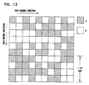
- FIGURE 13 a table illustrates a transmission data image used for de-interleaving the already interleaved two sets of data A and B.
- a preferred embodiment of the road communication system receives the above described dual interleaved subcarrier signal indicative of a plurality of sets of data.
- each box signifies a predetermined data unit.
- Four data units are defined to be a single FFT unit.
- the vertical direction is a data writing direction
- the horizontal direction is a data reading direction.
- the buffer image shows that a first set of data A is cross hatched while a second set of data B is blank.
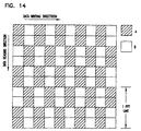
- FIGURE 14 a table illustrates an exemplary transmission data image of two sets of distributed data A and B based upon a predetermined algorithm.
- Each box signifies a predetermined data unit.
- Four data units are defined to be a single FFT unit.
- the vertical direction is a data reading direction, and the horizontal direction is a data writing direction.
- the buffer image shows that a first set of data A is cross hatched while a second set of data B is blank.
- the predetermined algorithm utilizes the FFT unit as a repetition cycle of distributing data sets A and B.
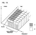
- FIGURE 15 a portion of a three-dimensional image of transmission data is mapped onto subcarriers and is illustrated along the time axis, the frequency axis and the power axis, and the buffer image contains the two sets of data A and B after an inverse Fourier function transformation is performed.
- the image shows that a first set of data A is cross hatched while a second set of data B is blank.
- the data sets A and B are divided into two subcarrier frequency blocks along the frequency axis.
- the block divisional pattern is constant over time.
- FIGURE 16 is a block diagram illustrating components of a preferred embodiment of the vehicle reception unit 109 according to the current invention.
- the vehicle reception unit 109 includes an antenna 10, a down-converter 191, a (QPSK) modulation circuit 192, a Fourier function transformation (FFT) circuit 193, a pair of decoders 196a, 196b, a switch circuit 194, a Frame Error Ratio (FER) evaluation circuit 195 and a position detection unit 198.
- the antenna 10 receives the radio signal transmitted from the control unit 6 and outputs to the down-converter 191.
- the down-converter 191 converts the received radio signal to an analog signal and outputs to the QPSK circuit 192.
- the QPSK circuit 192 includes a pair of multipliers 192a and 192b as well as a pair of analog to digital (A/D) converters 192c and 192d.
- the multipliers respectively multiply the analog signal by a sine signal and a cosine signal, and the outputs are respectively converted to a digital signal by the A/D converters 192c and 192d.
- the QPSK circuit 192 demodulates the digital signals and outputs the two demodulated digital signals to the FFT circuit 193, which performs the Fourier transformation on each of parallel input signals to generate output signals S1 and S2.
- the signals S1 and S2 each have a valid symbol length Ts.
- the FER evaluation circuit 195 controls the switch circuit 194 to select one of the output signals S1 and S2 for providing information including traffic and road conditions.
- One implementation of the switch circuit 194 is a semi conductor.
- an error correction decoding circuit In an alternative embodiment of the vehicle reception unit 109 according to the current invention, the following additional components are included: an error correction decoding circuit, a differential decoding circuit and an interleaving circuit for interleaving time and or frequency which respectively correspond to an error correction coding circuit, a differential coding circuit and an interleaving circuit for interleaving time and or frequency.
- FIGURE 17 a diagram illustrates components in a frame in a transmission signal.
- Each frame includes a header area, a data area and a cyclic redundancy check (CRC) area.
- a redundant code such as a CRC code is placed at a predetermined position in the frame for evaluating the reception condition, and the frame is transmitted via subcarriers S1 and S2.
- an error occurrence rate for frames is determined by reading the relevant code.
- the frame error occurrence rate is defined to be M2/(M1+M2) where M1 is a number of frames that is correctly received over a predetermined period of time while M2 is a number of frames that is incorrectly received over the same predetermined period of time.
- the subcarrier with the least error occurrence rate is selected. This selection is performed by the frame error rate (FER) evaluation circuit 195 in the above described vehicle reception unit 109 according to the current invention. Furthermore, the FER evaluation circuit 195 outputs the larger error frame occurrence rate to the position detection unit 198.
- FER frame error
- the position detection unit 198 determines a relative position by comparing a change in the error frame occurrence rate over time to a pair of predetermined threshold values Th1 and Th2.
- the position detection unit 198 indicates that the car or mobile unit 2 is near a cell boundary or an overlapping area of adjacent transmission areas when the error frame occurrence rate reaches beyond the first predetermined value Th1.
- the position detection unit 198 indicates that the car or mobile unit 2 is out of a cell boundary area and within a transmission area when the error frame occurrence rate reaches below the second predetermined value Th2.
- FIGURE 19 is a flow chart illustrating acts involved in a preferred process of detecting a relative position according to the current invention. These acts are generally performed within the position detection unit 198. After both a memory and a flag are initialized to zeroes in act A1, a frame error occurrence rate is periodically received in act A2. The frame error occurrence rate is compared to a previously stored frame error occurrence rate in the memory in act A3. If the flag value is 0 in act A4 but the new frame error occurrence rate is not larger than the previously stored frame error occurrence rate in act A5, the preferred process returns to the act A2.
- the flag value is 0 in act A4 and the new frame error occurrence rate is larger than the previously stored frame error occurrence rate in act A5, the memory is rewritten with the new frame error occurrence rate in act A6.
- the frame error occurrence rate in the memory is compared to a predetermined first threshold value Th1. If the frame error occurrence rate in the memory is not larger than the first predetermined threshold value Th1 in act A8, the preferred process returns to the act A2. If the frame error occurrence rate in the memory is larger than the first predetermined threshold value Th1 in act A8, the flag is now set to 1 in act A9. The position is outputted in act A10, and the preferred process returns to the act A2.
- the preferred process returns to the act A2.
- the flag value is 1 in act A4 and the new frame error occurrence rate is smaller than the previously stored frame error occurrence rate in act A11
- the memory is rewritten with the new frame error occurrence rate in act A12.
- the frame error occurrence rate in the memory is compared to a predetermined second threshold value Th2. If the frame error occurrence rate in the memory is not smaller than the second predetermined threshold value Th2 in act A14, the preferred process returns to the act A2.
- the stationary units transmit the same informational data to the car using a common carrier frequency.
- the informational signal is modulated at each of the stationary units based upon a predetermined common orthogonal frequency division multiplex (OFDM) modulation technique.
- the informational signal is also interleaved in the time dimension.
- FIGURES 20A and 20B respectively illustrate another preferred embodiment of the reception unit and the transmission unit according to the current invention.
- FIGURE 20A a block diagram illustrates components of the preferred embodiment of the transmission unit 200 according to the current invention.
- transmission components of the transmission unit 200 utilizes the orthogonal frequency division multiplex (OFDM) modulation technique which multiplexes a plurality of orthogonal frequency caters for transmitting divided data.
- OFDM orthogonal frequency division multiplex
- the transmission unit 200 generally includes an interleave unit 201, an inverse Fourier function transformation (IFFT) circuit 202, a quadrature phase shift keying (QPSK) modulation circuit 204 and an up-converter 206.
- the interleave unit 201 performs interleaving of the input signals S1 and S2.
- the IFFT circuit 202 performs the inverse Fourier transformation on each of parallel input signals S1 and S2 and serially translates the inversely transformed data back to serial data.
- the IFFT circuit 202 time compresses the serial data and determines a guard time by placing a rear symbol in a forward position.
- the IFFT circuit 202 outputs two signals to the QPSK circuit 204. One signal has either 0° or 180° phase, and the other signal has either 90° or 270° phase.
- the QPSK circuit 204 modulates output signals from the IFFT circuit 202 and the up-converter 206 generates a radio signal.
- the QPSK circuit 204 further includes a pair of digital-to-analog converters (D/A) 204a and 204b as well as a pair of multipliers 204c and 204d.
- the first D/A converter 204a outputs a signal to the multiplier 204c to multiply by a sine signal so as to produce an output signal having either 0° or 180° phase.
- the second D/A converter 204b outputs a signal to the multiplier 204d to multiply by a cosine signal so as to produce an output signal having either 90° or 270° phase.
- the up-converter 206 converts the output signal from the QPSK circuit 204 to a radio frequency.
- the up-converter 206 includes a local oscillator 206c, a PLL 206b and a multiplier 206a. It is desired that the precision of the local oscillator 206c be the same order as a quotient of a speed of a car divided by the radio signal speed in view of a Doppler effect caused by the moving car.
- a commercially available oscillator can sufficiently match the above required precision.
- the oscillator 206c outputs a signal to the PLL 206b, and the output of the PLL 206b is multiplied with the output signal from the up-converter 206 before being outputted from the transmission unit 200.
- the output signal from the up-converter 206 is inputted into the antenna 204 via the cable 205 and is transmitted as a radio signal from the antenna 204.
- the reception unit 209 includes an antenna 210, a down-converter 212, a (QPSK) modulation circuit 214, a Fourier function transformation (FFT) circuit 216, a de-interleave unit 218, and a switch control circuit 220.
- the antenna 210 receives the radio signal transmitted from the transmission unit 200 and outputs to the down-converter 212.
- the down-converter 212 converts the received radio signal to an analog signal and outputs to the QPSK circuit 214.
- the down-converter 212 further includes a multiplier 212a, a PLL unit 212b and an oscillator 212c.
- the QPSK circuit 214 includes a pair of multipliers 214a and 214b as well as a pair of analog to digital (A/D) converters 214c and 214d.
- the multipliers respectively multiply the analog signal by a sine signal and a cosine signal, and the outputs are respectively converted to a digital signal by the A/D converters 214c and 214d.
- the QPSK circuit 214 demodulates the digital signals and outputs the two demodulated digital signals to the FFT circuit 216, which performs the Fourier transformation on each of parallel input signals to generate output signals S1 and S2.
- the signals S1 and S2 each have a valid symbol length Ts.
- the de-interleave unit 218 further processes the demodulated but still interleaved signals S1 and S2.
- the switch circuit 220 select one of the output signals S1 and S2.
- One implementation of the switch circuit 220 is a semi conductor.
- FIGURE 21A shows that each of the base stations BS1 through BS6 transmits two types of data respectively in an upper frequency side and a lower frequency side. These frequency sides may be implemented as a segment.
- a base station BS1 transmits a data type A on the upper side frequency as well as a data type C on the lower side frequency.
- the upper side transmits two different data sets A and B, and as a mobile receiving unit moves in the direction from the BS1 to the BS6, the mobile receiving unit switches from the data set A to the data set B.
- the same mobile receiving unit keeps receiving the common data set C throughout the same travel.
- the data sets A and B may be containing location-sensitive information such as speed limit and so on while the data set C may be system-related information.
- FIGURE 21B shows that between the base stations BS3 and BS4, interference occurs as indicated by hatched lines. Because of the interference, the transition from the data set A to B is not seamless and interrupted. This interruption is critical for certain types of prioritized data such as graphics.
- FIGURES 21C and 21D illustrate one exemplary method of improving the seamless reception in the data transition.
- FIGURE21C shows the same data transmission in the upper side.
- the base stations BS3 and 4 now transmit the interfered A data set in lieu of the original common C data set in the lower side.
- FIGURE 21D shows that during the interference in the transition of the data set A to B in the upper side, the mobile receiving unit can switch to the lower side to receive the data set A.
- the mobile receiving unit switches back to the upper side.
- This method assumes that the data set C has a lower priority than the data set A or B, and the unavailability of the data set C from the stations BS3 and BS4 is not critical.
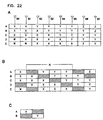
- FIGURES 22A, 22B and 22C a more complex example is illustrated to further explain how the segmented transmission improves the efficiency.
- Stationary stations St0 through St7 are adjacently located, and each of the stationary stations St0-St7 transmits data using five segmented signals A through E.
- the segment comprises a predetermined number of subcarriers.
- the stationary station transmits data X using the segments A, B and C as well as data W using the segment D and E.
- the stationary stations St0-St7 transmits data as shown in FIGURE 22A, some interference occurs due to two different data on the same segmented signal from the two adjacent stations.
- the signal interference is illustrated in FIGURE 22B.
- the adjacent stationary stations St1 and St2 respectively transmit data X and Y
- there is some interference between the two stationary stations on the segment A and the interference is indicated by hatched lines.
- the signal interference emerges also in a certain predetermined sequence.
- a number N is a number which indicates a size of the sequence.
- the stationary station St1 experiences the interference, and there are four stationary stations including the stationary station St1 before the next affected stationary station St5. The number N is 4 in this sequence.
- FIGURE 22C illustrates that some interference is indicated for transmitting data x and y using two segments A and B between two adjacent stationary stations.
- the usage efficiency of a given frequency band is generally defined as 1-1/N.
- the use of the five segments over the two segments improves the usage efficiency of a given frequency band by 25%.
Landscapes
- Engineering & Computer Science (AREA)
- Signal Processing (AREA)
- Computer Networks & Wireless Communication (AREA)
- Multimedia (AREA)
- Physics & Mathematics (AREA)
- General Physics & Mathematics (AREA)
- Mobile Radio Communication Systems (AREA)
Applications Claiming Priority (6)
| Application Number | Priority Date | Filing Date | Title |
|---|---|---|---|
| JP4981599 | 1999-02-26 | ||
| JP4981599 | 1999-02-26 | ||
| JP11130292A JP3045167B1 (ja) | 1999-02-26 | 1999-05-11 | 路車間通信システム |
| JP13029299 | 1999-05-11 | ||
| JP30966499A JP3289717B2 (ja) | 1999-02-26 | 1999-10-29 | 車両位置検出システム |
| JP30966499 | 1999-10-29 |
Publications (2)
| Publication Number | Publication Date |
|---|---|
| EP1032231A2 true EP1032231A2 (de) | 2000-08-30 |
| EP1032231A3 EP1032231A3 (de) | 2000-10-11 |
Family
ID=27293749
Family Applications (1)
| Application Number | Title | Priority Date | Filing Date |
|---|---|---|---|
| EP00301348A Withdrawn EP1032231A3 (de) | 1999-02-26 | 2000-02-21 | Nahtloses Zweiwegekommunikationssystem langs Strassen |
Country Status (3)
| Country | Link |
|---|---|
| US (1) | US6546249B1 (de) |
| EP (1) | EP1032231A3 (de) |
| KR (1) | KR20000076736A (de) |
Cited By (2)
| Publication number | Priority date | Publication date | Assignee | Title |
|---|---|---|---|---|
| WO2003105513A3 (en) * | 2002-06-07 | 2004-05-06 | Nortel Networks Ltd | Systems and methods for channel allocation for forward-link in multi-user systems |
| EP1359695A3 (de) * | 2002-05-02 | 2006-01-11 | EADS Astrium GmbH | Verfahren zum Interleaving von Navigationsdaten |
Families Citing this family (15)
| Publication number | Priority date | Publication date | Assignee | Title |
|---|---|---|---|---|
| EP1317814A1 (de) * | 2000-09-12 | 2003-06-11 | Kvaser Consultant Ab | Anordnung mit einer anzahl von einheiten, die über ein drahtloses verbindungssystem miteinander kommunizieren können, und verfahren zur verwendung mit einem solchen system |
| US6947748B2 (en) | 2000-12-15 | 2005-09-20 | Adaptix, Inc. | OFDMA with adaptive subcarrier-cluster configuration and selective loading |
| JP4031707B2 (ja) * | 2000-12-15 | 2008-01-09 | アダプティックス インコーポレイテッド | グループベースのサブキャリア割当による多重キャリア通信 |
| US7139237B2 (en) * | 2000-12-29 | 2006-11-21 | Motorola, Inc. | Method and system for multirate multiuser modulation |
| US6772062B2 (en) * | 2001-05-31 | 2004-08-03 | The Regents Of The University Of California | Intelligent ultra high speed distributed sensing system and method for sensing roadway markers for intelligent vehicle guidance and control |
| JP3396815B2 (ja) * | 2001-06-20 | 2003-04-14 | 富士通株式会社 | データ伝送方法及びデータ伝送装置 |
| US7480239B1 (en) | 2001-11-27 | 2009-01-20 | Cisco Technology, Inc. | Method and apparatus for true priority based connection establishment within a PNNI ATM network |
| US6993333B2 (en) | 2003-10-16 | 2006-01-31 | Flarion Technologies, Inc. | Methods and apparatus of improving inter-sector and/or inter-cell handoffs in a multi-carrier wireless communications system |
| US7532574B1 (en) | 2003-10-02 | 2009-05-12 | Cisco Technology, Inc. | Method and apparatus for improved priority based connection establishment within a PNNI ATM network |
| US7573851B2 (en) | 2004-12-07 | 2009-08-11 | Adaptix, Inc. | Method and system for switching antenna and channel assignments in broadband wireless networks |
| JP2006270778A (ja) * | 2005-03-25 | 2006-10-05 | Denso Corp | 車載無線通信機 |
| FR2887762B1 (fr) * | 2005-06-29 | 2007-10-12 | Ldr Medical Soc Par Actions Si | Instrumentation d'insertion de prothese de disque intervertebral entre des vertebres |
| US8260145B2 (en) * | 2008-03-12 | 2012-09-04 | Deepnarayan Gupta | Digital radio frequency tranceiver system and method |
| JP2009239766A (ja) * | 2008-03-28 | 2009-10-15 | Fujitsu Ltd | 無線基地局、移動局および無線通信方法 |
| US8121805B2 (en) * | 2009-09-30 | 2012-02-21 | Mitsubishi Electric Research Laboratories, Inc. | Method and system for determining locations of moving objects with maximum length sequences |
Citations (2)
| Publication number | Priority date | Publication date | Assignee | Title |
|---|---|---|---|---|
| JPH09238104A (ja) | 1996-02-29 | 1997-09-09 | Sumitomo Electric Ind Ltd | 道路連続通信システム |
| JPH11266194A (ja) | 1997-12-25 | 1999-09-28 | Sumitomo Electric Ind Ltd | 路車間通信システム |
Family Cites Families (22)
| Publication number | Priority date | Publication date | Assignee | Title |
|---|---|---|---|---|
| US4306313A (en) * | 1979-10-11 | 1981-12-15 | International Telephone And Telegraph Corporation | High reliability optical fiber communication system |
| US4953157A (en) * | 1989-04-19 | 1990-08-28 | American Telephone And Telegraph Company | Programmable data packet buffer prioritization arrangement |
| JPH03126328A (ja) | 1989-10-12 | 1991-05-29 | Toshiba Corp | 無線基地局の出力選択方式 |
| US5101501A (en) * | 1989-11-07 | 1992-03-31 | Qualcomm Incorporated | Method and system for providing a soft handoff in communications in a cdma cellular telephone system |
| US5267261A (en) * | 1992-03-05 | 1993-11-30 | Qualcomm Incorporated | Mobile station assisted soft handoff in a CDMA cellular communications system |
| DE4424778C1 (de) | 1994-07-14 | 1995-11-16 | Grundig Emv | Verfahren zur Übertragung und Verfahren zum Empfang von Lokalen Rundfunkprogrammen in einem Gleichwellennetz sowie zugehörige Sender und Empfänger |
| JP3538907B2 (ja) * | 1994-08-19 | 2004-06-14 | セイコーエプソン株式会社 | 移動体用の放送波受信装置 |
| JPH08241495A (ja) | 1995-03-02 | 1996-09-17 | Sumitomo Electric Ind Ltd | 安全走行制御システム |
| JPH0998465A (ja) * | 1995-09-29 | 1997-04-08 | Nec Corp | 携帯無線電話制御法及び携帯無線電話機 |
| DE19538302C2 (de) * | 1995-10-16 | 2001-03-22 | Bosch Gmbh Robert | Verfahren zur terrestrischen Übertragung digitaler Signale |
| US5920821A (en) * | 1995-12-04 | 1999-07-06 | Bell Atlantic Network Services, Inc. | Use of cellular digital packet data (CDPD) communications to convey system identification list data to roaming cellular subscriber stations |
| JPH09284251A (ja) | 1996-04-10 | 1997-10-31 | Jisedai Digital Television Hoso Syst Kenkyusho:Kk | 受信装置 |
| US6125276A (en) * | 1996-09-06 | 2000-09-26 | Telefonaktiebolaget Lm Ericsson (Publ) | Inter-exchange signaling for in-call service change requests |
| US6016426A (en) * | 1996-10-10 | 2000-01-18 | Mvs, Incorporated | Method and system for cellular communication with centralized control and signal processing |
| JP3369063B2 (ja) * | 1996-10-18 | 2003-01-20 | 松下電器産業株式会社 | 移動通信端末 |
| JP3687229B2 (ja) * | 1996-11-08 | 2005-08-24 | ソニー株式会社 | 通信方法、基地局及び端末装置 |
| JPH10262274A (ja) * | 1997-03-19 | 1998-09-29 | Fujitsu Ltd | 移動局及びソフトハンドオフ方法 |
| JPH10261193A (ja) | 1997-03-21 | 1998-09-29 | Mitsubishi Electric Corp | 車両走行制御システム |
| JP2990098B2 (ja) * | 1997-05-21 | 1999-12-13 | 埼玉日本電気株式会社 | 端末主導型移動通信システム |
| US6330609B1 (en) * | 1997-11-07 | 2001-12-11 | Lucent Technologies, Inc. | Admission control system and method for media-on-demand servers |
| CN1242564C (zh) * | 1998-02-19 | 2006-02-15 | 高通股份有限公司 | 蜂窝系统中利用nt/i0值的前向链路功率控制 |
| CA2264125C (en) * | 1998-03-03 | 2003-05-06 | Nec Corporation | Method of controlling transmission power in a cellular type mobile communication system |
-
2000
- 2000-02-16 US US09/504,705 patent/US6546249B1/en not_active Expired - Fee Related
- 2000-02-21 EP EP00301348A patent/EP1032231A3/de not_active Withdrawn
- 2000-02-25 KR KR1020000009376A patent/KR20000076736A/ko not_active Withdrawn
Patent Citations (2)
| Publication number | Priority date | Publication date | Assignee | Title |
|---|---|---|---|---|
| JPH09238104A (ja) | 1996-02-29 | 1997-09-09 | Sumitomo Electric Ind Ltd | 道路連続通信システム |
| JPH11266194A (ja) | 1997-12-25 | 1999-09-28 | Sumitomo Electric Ind Ltd | 路車間通信システム |
Non-Patent Citations (1)
| Title |
|---|
| "Fiber/Radio For the Provision of Cordless/Mobile Elephony Services in The Access Network", ELECTRON. LETT., vol. 26, no. 24, November 1990 (1990-11-01) |
Cited By (4)
| Publication number | Priority date | Publication date | Assignee | Title |
|---|---|---|---|---|
| EP1359695A3 (de) * | 2002-05-02 | 2006-01-11 | EADS Astrium GmbH | Verfahren zum Interleaving von Navigationsdaten |
| US7376096B2 (en) | 2002-05-02 | 2008-05-20 | Astrium Gmbh | Process for interleaving navigation data |
| WO2003105513A3 (en) * | 2002-06-07 | 2004-05-06 | Nortel Networks Ltd | Systems and methods for channel allocation for forward-link in multi-user systems |
| US9125061B2 (en) | 2002-06-07 | 2015-09-01 | Apple Inc. | Systems and methods for channel allocation for forward-link multi-user systems |
Also Published As
| Publication number | Publication date |
|---|---|
| EP1032231A3 (de) | 2000-10-11 |
| KR20000076736A (ko) | 2000-12-26 |
| US6546249B1 (en) | 2003-04-08 |
Similar Documents
| Publication | Publication Date | Title |
|---|---|---|
| US6546249B1 (en) | Seamless two-way roadway communication system | |
| US5442646A (en) | Subcarrier communication system | |
| TWI535250B (zh) | 傳輸器及傳輸方法 | |
| EP0744841A2 (de) | Verfahren und Einrichtung zur Übertragung und Empfang von Burstsignalen unter Verwendung von Zeitdiversity und Antennenumschalten | |
| RU2444144C2 (ru) | Способ и система для передачи и приема сигналов | |
| CN1091569A (zh) | 两种方式的无线电通信单元 | |
| CN101582739A (zh) | 数字广播信号的发送装置、发送方法和发送系统 | |
| US9628205B2 (en) | Method and apparatus for transmitting and receiving broadcast service data in a broadcasting communication system, method for configuring the broadcast service data, and frame including the broadcast service data | |
| US20160234454A1 (en) | Broadcast receiving device and method for operating the same | |
| JP2966821B2 (ja) | 伝送制御信号送信方式と送受信装置 | |
| US7385915B2 (en) | Apparatus, and associated method, for facilitating communication allocation in a radio communication system | |
| CN101926110B (zh) | 广播通信系统中用于发送和接收广播服务数据的方法和装置、用于配置该广播服务数据的方法、以及包括该广播服务数据的帧 | |
| JP3045167B1 (ja) | 路車間通信システム | |
| US20050135517A1 (en) | Increasing effective number of data tones in a multi-antenna multi-tone communication system | |
| JP3362726B2 (ja) | 路車間通信システム | |
| TWI502900B (zh) | 接收器及接收方法 | |
| CN101582740A (zh) | 数字广播信号的发送装置、发送方法和发送系统 | |
| CA2522889C (en) | Rate adaptive data broadcast technique | |
| KR20090044952A (ko) | 방송통신 시스템에서 제어 정보를 송수신 하는 방법 및장치 | |
| CN102957942B (zh) | 数字多媒体广播中传输数据的方法、装置和系统 | |
| Moriyama et al. | Digital outside-broadcasting-link using OFDM modulation scheme | |
| Miyasaka et al. | A study on the scattered pilot pattern of mobile reception for an advanced ISDB-T | |
| JP3289717B2 (ja) | 車両位置検出システム | |
| Bedicks et al. | Performance evaluation of Brazilian DTV mobile reception | |
| KR20010064229A (ko) | 에프엠 대역에서의 디지털 오디오 방송 시스템 |
Legal Events
| Date | Code | Title | Description |
|---|---|---|---|
| PUAI | Public reference made under article 153(3) epc to a published international application that has entered the european phase |
Free format text: ORIGINAL CODE: 0009012 |
|
| PUAL | Search report despatched |
Free format text: ORIGINAL CODE: 0009013 |
|
| AK | Designated contracting states |
Kind code of ref document: A2 Designated state(s): AT BE CH CY DE DK ES FI FR GB GR IE IT LI LU MC NL PT SE |
|
| AX | Request for extension of the european patent |
Free format text: AL;LT;LV;MK;RO;SI |
|
| AK | Designated contracting states |
Kind code of ref document: A3 Designated state(s): AT BE CH CY DE DK ES FI FR GB GR IE IT LI LU MC NL PT SE |
|
| AX | Request for extension of the european patent |
Free format text: AL;LT;LV;MK;RO;SI |
|
| RIC1 | Information provided on ipc code assigned before grant |
Free format text: 7H 04Q 7/36 A, 7H 04L 5/02 B |
|
| 17P | Request for examination filed |
Effective date: 20010319 |
|
| AKX | Designation fees paid |
Free format text: AT BE CH CY DE DK ES FI FR GB GR IE IT LI LU MC NL PT SE |
|
| 17Q | First examination report despatched |
Effective date: 20060630 |
|
| 17Q | First examination report despatched |
Effective date: 20060630 |
|
| STAA | Information on the status of an ep patent application or granted ep patent |
Free format text: STATUS: THE APPLICATION IS DEEMED TO BE WITHDRAWN |
|
| 18D | Application deemed to be withdrawn |
Effective date: 20131213 |
|
| REG | Reference to a national code |
Ref country code: DE Ref legal event code: R079 Free format text: PREVIOUS MAIN CLASS: H04Q0007360000 Ipc: H04W0016000000 |
|
| REG | Reference to a national code |
Ref country code: DE Ref legal event code: R079 Free format text: PREVIOUS MAIN CLASS: H04Q0007360000 Ipc: H04W0016000000 Effective date: 20140526 |