EP1032083A2 - Serre-câble pour le maintien mécanique et la connexion électrique d'un câble - Google Patents
Serre-câble pour le maintien mécanique et la connexion électrique d'un câble Download PDFInfo
- Publication number
- EP1032083A2 EP1032083A2 EP00103407A EP00103407A EP1032083A2 EP 1032083 A2 EP1032083 A2 EP 1032083A2 EP 00103407 A EP00103407 A EP 00103407A EP 00103407 A EP00103407 A EP 00103407A EP 1032083 A2 EP1032083 A2 EP 1032083A2
- Authority
- EP
- European Patent Office
- Prior art keywords
- cable
- cable clamp
- pair
- clamp according
- housing
- Prior art date
- Legal status (The legal status is an assumption and is not a legal conclusion. Google has not performed a legal analysis and makes no representation as to the accuracy of the status listed.)
- Granted
Links
Images


Classifications
-
- H—ELECTRICITY
- H01—ELECTRIC ELEMENTS
- H01R—ELECTRICALLY-CONDUCTIVE CONNECTIONS; STRUCTURAL ASSOCIATIONS OF A PLURALITY OF MUTUALLY-INSULATED ELECTRICAL CONNECTING ELEMENTS; COUPLING DEVICES; CURRENT COLLECTORS
- H01R13/00—Details of coupling devices of the kinds covered by groups H01R12/70 or H01R24/00 - H01R33/00
- H01R13/58—Means for relieving strain on wire connection, e.g. cord grip, for avoiding loosening of connections between wires and terminals within a coupling device terminating a cable
- H01R13/582—Means for relieving strain on wire connection, e.g. cord grip, for avoiding loosening of connections between wires and terminals within a coupling device terminating a cable the cable being clamped between assembled parts of the housing
Definitions
- the invention relates to a cable clamp for mechanical holding and electrical Connect a cable, with a two-piece housing and one Clamping device for a cable to be inserted into the housing.
- Such a cable clamp can be installed in a control cabinet, for example his.
- a cable clamp There are various requirements for such a cable clamp. To the one must enable reliable electrical connection of the cable. At the same time, strain relief must be provided, by means of which the cable is inserted in such a way the cable clamp is held that tensile loads applied to the cable are not are transmitted to the electrical connection, but previously derived into the housing become. Finally, such a cable clamp can be used to create a electrical shielding in the area of the connection of the cable with the electrical Provide connection.
- Two concepts are known from the prior art by means of which attempts are made will, both a secure mechanical hold of the cable in the cable clamp as well to ensure good electrical shielding.
- One concept provides one Form cable receptacle, on which several screws are provided, which in Attack the screwed-in condition on the jacket of the cable. If the cable is connected to a Shielding is provided, this can be 180 ° on the jacket of the cable bent back and contacted there.
- Another concept is one Press the retaining ring onto the sheath of the cable. This ring is then in one appropriate receptacle of the housing inserted and acts as a strain relief. If before the pressing of the retaining ring exposed a shield of the cable and on the Jacket is bent back, the retaining ring can contact this shield and together with an electrically conductive receptacle serve to provide good shielding to ensure the cable clamp.
- the object of the invention is a cable clamp of the type mentioned Art in such a way that a cable to be inserted into the cable clamp minimal effort mechanically reliable can be set, while at the same time there should be the possibility of a large shielding of the cable to be inserted Effort to contact electrically.
- a cable clamp at the beginning mentioned type, which is characterized in that at least two pairs of mutually opposite deformation elements are provided, which at attack closed housing and inserted cable and deform it, wherein the deformation elements of the first pair face each other in a clamping direction opposite, which deviates from the clamping direction in which the Deformation elements of the second pair are opposite, and wherein the two pairs, viewed along the longitudinal axis of the cable to be inserted into the cable clamp, are arranged one behind the other.
- clamping direction Direction understood along which the two deformation elements of a pair one Apply clamping force to the inserted cable, this direction generally also applies the direction of the shortest connection between the two deformation elements together.
- a cable clamp according to the invention is based on the Basic idea that the holding force to be provided for the purpose of strain relief of at least two pairs of deformation elements arranged one behind the other provided. These deformation elements are designed so that those of them caused deformation of the cable differs in the direction. If for example, the first and the second deformation element pair the cable with im Deform the initial state of the round cross-section into an oval cross-section from the longer main axis of the oval cross section in the area of the first Deformation element pair predetermined direction from the direction from that longer main axis of the second oval cross-section is determined.
- the evoked Deformation does not necessarily have to be oval or elliptical Cross section of the cable.
- the deformation behavior of the cable can also be constricted, for example Cross section result. In any case, this results in the clamping direction in which the Deformation elements are opposite, a reduction in the diameter of the Cross-section, while there is an enlargement approximately perpendicular to this clamping direction of the diameter of the cross section. Because of the different orientation the deformed cross-sections of the cable pulls the cable out of the Cable clamp in addition to the frictional forces at the points of attack Deformation elements are generated on the cable, still a deformation resistance opposite. If the cable were to be pulled out, every position of the Cable which is deformed in a first direction on a pair of deformation elements, deformed in another direction in the subsequent pair of deformation elements become. This multiple deformation of the cross section acts from the Material stiffness of the cable against the resulting resistance to deformation.
- the from the first pair of deformation elements determined clamping direction by about 90 ° is rotated relative to the clamping direction by the second Deformation element pair is determined.
- the second deformation element pair between the third pair of deformation elements and the first Deformation elements pair is arranged and that of the third Deformation element pair determined clamping direction approximately with that of the first Deformation elements pair certain clamping direction matches.
- This Design creates three deformed cross sections of the cable, each of which is differ from the adjacent cross section. In this way the Strain relief effect improved.
- a deformation element of a pair on the first part of the housing and the associated other deformation element on the second part of the housing is attached. This design results in a minimal Assembly effort. The cable only needs to be inserted into one of the housing parts. The strain relief results automatically when the second housing part attached and connected to the first housing part.
- a deformation element consists of a rib that is perpendicular in one plane extends to the longitudinal axis of the cable to be received in the cable clamp.
- the rib on the cable has a straight edge attacks with respect to a tangent to the outer circumference of the cable to be inserted is slightly inclined.
- the insertion of the cable is facilitated;
- the risk of damage to the cable during insertion is reduced.
- the two edges preferably lie in a clamping direction opposite, which is approximately perpendicular to the direction in which the housing is closed.
- the protrusion has a vertex that is on the cable attacks.
- the radius of curvature of this vertex Art and how the cable is deformed by the protrusion. If for example, the radius of curvature at the apex is smaller than the radius of the The outer circumference of the cable to be inserted results from sufficient deformability of the cable a deformed cross section, which corresponds approximately to an ellipse, which in the area its short semiaxes is severely constricted, namely in the area in which the Crest apex attacks. If, on the other hand, the cable is only a small one Has deformability, the vertices acting on the cable lead to the fact that there is an oval cross section.
- the two projections in one another Clamping direction opposite, which corresponds approximately to the direction in which the Housing is closed.
- At least one is U-shaped Holding section provided, the distance between the two legs of the Holding section is smaller than the outer diameter of the cable to be inserted.
- This Holding section is used to fix the cable in one housing part before the other Housing part is attached.
- the holding section is preferably opposite the deformation elements offset laterally so that the cable to be inserted is deflected by a central axis.
- the lateral deflection of the cable increases the strain relief resistance provided.
- the Deformation elements pairs are electrically conductive and on a shield of the attack the inserted cable in an electrically conductive manner.
- the housing is also electrically conductive, so that the im Housing trained electrical connection of the cable is also shielded.
- the electrical contact between the shield of the cable and the electrically conductive Deformation element pairs can be achieved in two ways: Firstly the pairs of deformation elements can be designed as cutting edges, the one Penetrate the sheathing of the cable and attack the shielding of the cable, so that it is electrically conductively contacted.
- the shielding of the Cable is exposed before insertion in the cable clamp and 180 ° on the jacket of the Fold the cable back so that it lies on the outer circumference of the cable.
- the Deformation element pairs then automatically attack the shield, whereby at the same time the mechanical hold of the cable is achieved in the cable clamp.
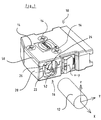
- a cable clamp 10 can be seen in FIG. It serves an electrical cable 12 mechanically record and connect electrically.
- the cable clamp 10 has a first housing part 20 and a second housing part 50
- the second housing part 50 can be attached to the first housing part 20 in the manner of a cover attached and fastened to it with three screws 14.
- the two Housing parts can consist of plastic and be made in one piece, be hinged to each other, for example, by a plastic film hinge.
- the housing 10 is generally designated 16 Strain relief provided, which consists of a first pair of deformation elements 22, 52, a second pair of deformation elements 24, 54 and a third pair of Deformation elements 26, 56 there.
- the strain relief 16 is as follows described in more detail with reference to Figures 2 to 5.
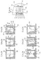
- Figure 2a is a schematic section through the strain relief 16 along the plane X-Y (see Figure 1) shown.
- Figures 2b to 2g cross sections are perpendicular to Axis X is shown in the area of the strain relief 16, the respective plane in FIG 2a is designated.
- the strain relief 16 has one on the outside of the cable clamp 10 Input cross section that is larger than the cross section of the cable 12 to be received is. As can be seen in FIG. 36, the cable 12 runs freely through the input cross section through it.
- a U-shaped Stop section At the entrance cross section in the plane c is a U-shaped Stop section. This is provided by two on the first housing part 20 Legs 28, 30 formed. The legs 28, 30 lie at such a distance from one another opposite that there was a slight deformation of the originally circular Cross section of the cable 12 comes to an oval cross section. This is too in Figure 3c see; the original cross-section is indicated by a solid line, and the deformed cross section is indicated by the double hatching. The two legs 28, 30 are opposite a central axis M which is aligned with the X axis of the cable coincides, offset laterally so that the cable 12 is deflected to the side.
- the deformation elements are designed as ribs, wherein the rib 22 is provided on the first housing part 20, while the rib 52 on second housing part 52 is provided.
- the ribs have two straight edges 23, 53 on, which are intended to attack the cable 12 (see Figure 3d)
- the two Edges 23, 53 face each other in a clamping direction, in the direction corresponds in which a clamping effect is exerted on the cable 12 Edges 23, 53 with respect to the direction in which the two housing parts 20, 50 are joined together and which is symbolized by the arrow P in FIG. 2d, slightly arranged at an angle, so that when the two are put together Housing parts 20, 50 results in an increasing wedge effect.
- edges 23, 53 run to the free ends of the ribs 22, 52 in insertion bevels from the automatic positioning and centering of the cable in the Pair of clamping elements 22, 52 guaranteed. Furthermore, in the area of the free ends Ribs 22, 52 recordings in the corresponding opposite housing part provided so that the spreading forces occurring during the deformation of the cable safely are reliably received and do not lead to any deformation of the housing can.
- a section with the one in FIG. 2b is connected to the deformation elements 22, 52 shown cross section, in which the cable returns to its undeformed has circular cross section.
- a second pair of deformation elements 24, 54 arranged. Deviating from the first pair of deformation elements are here rib-shaped projections used with their apices 25, 55 on the attack cable 12 to be picked up.
- the radius of curvature r at the apex of the Deformation elements 24, 54 (see also Figure 4) is smaller than the radius of the Outer periphery of the cable 12.
- the first deformation element 24 is formed on the first housing part 20, and that second deformation element 54 is formed on the second housing part 50. Furthermore, on second housing part 50 a receptacle for the deformation cross section e laterally delimiting rib extending from the first housing part 20 intended. In this way, the clamping force between the apexes 25, 55 automatically caused when the two housing parts 20, 50 are joined, whereby the receptacle for the rib extending from the first housing part 20 for a precise positioning of the two housing parts relative to each other ensures.
- the second pair of deformation elements is followed by a section like it is shown in Figure 2b.
- the cable to be picked up has one circular cross section.
- a holding section is then arranged in the plane g, as it basically consists of level c is known.
- the two legs 32, 34 determine a cross section that is offset in the opposite direction with respect to the central axis M as in the plane c.
- a cross section is arranged towards the inside of the housing, as it is from level b is known.
- the cable therefore has a circular cross section.
- This sequence of pairs of deformation elements results in the negative X direction of the cable considers a sequence of different cable cross sections:
- the cable When entering the cable clamp 10, the cable has a round cross section.
- the cable is then deformed into an oval cross section, the longer one Semi-axes are aligned in the Z direction, since the clamping direction is roughly along the Y axis is aligned.
- the cable is tied into one elliptical cross-section deformed, with the longer semiaxes of the ellipse in the Y direction are aligned since the clamping direction is aligned along the Z axis is.
- the cable is reshaped into an elliptical cross-section, whose longer semi-axes are aligned in the Z direction.
- the deformation elements in the plane e together with those from level d and / or level f can be used to shield the To contact the cable electrically. Because this way, the shielding in total at least four points are contacted, which are at an angular distance of 90 ° to each other are arranged with a slight offset in the X direction, which corresponds to Contacting the shielding qualitatively approximates such contacting received, for example, by a clamp surrounding the shield by 360 ° becomes.
Applications Claiming Priority (2)
| Application Number | Priority Date | Filing Date | Title |
|---|---|---|---|
| DE19908455A DE19908455C2 (de) | 1999-02-26 | 1999-02-26 | Kabelklemme zum mechanischen Halten und elektrischen Anschließen eines Kabels |
| DE19908455 | 1999-02-26 |
Publications (3)
| Publication Number | Publication Date |
|---|---|
| EP1032083A2 true EP1032083A2 (fr) | 2000-08-30 |
| EP1032083A3 EP1032083A3 (fr) | 2003-04-09 |
| EP1032083B1 EP1032083B1 (fr) | 2004-11-24 |
Family
ID=7899030
Family Applications (1)
| Application Number | Title | Priority Date | Filing Date |
|---|---|---|---|
| EP00103407A Expired - Lifetime EP1032083B1 (fr) | 1999-02-26 | 2000-02-24 | Serre-câble pour le maintien mécanique et la connexion électrique d'un câble |
Country Status (3)
| Country | Link |
|---|---|
| US (1) | US6261121B1 (fr) |
| EP (1) | EP1032083B1 (fr) |
| DE (2) | DE19908455C2 (fr) |
Families Citing this family (6)
| Publication number | Priority date | Publication date | Assignee | Title |
|---|---|---|---|---|
| DE102004043518B3 (de) | 2004-09-08 | 2006-05-18 | Kathrein-Werke Kg | Vorrichtung zum Anschluss eines Koaxialkabels an ein Gehäuse |
| US7112086B1 (en) * | 2005-04-08 | 2006-09-26 | Hon Hai Precision Ind. Co., Ltd. | Electrical cable assembly having cable guide |
| JP4775907B2 (ja) * | 2006-11-22 | 2011-09-21 | Smk株式会社 | 防水型コネクタ及び中継コネクタ |
| DE102015104537A1 (de) * | 2015-03-25 | 2016-09-29 | Lisa Dräxlmaier GmbH | Elektrische Verbindung in Kabelbäumen für Fahrzeuge sowie Verfahren zur Herstellung einer solchen Verbindung |
| EP3099053B1 (fr) * | 2015-05-27 | 2017-06-21 | Axis AB | Boîtier avec décharge de traction pour un câble et caméra comprenant un tel boîtier |
| DE102018132823A1 (de) * | 2018-12-19 | 2020-06-25 | Rosenberger Hochfrequenztechnik Gmbh & Co. Kg | Kabelsteckverbinderanordnung, Kabelsteckverbinder und Pressmittel |
Citations (6)
| Publication number | Priority date | Publication date | Assignee | Title |
|---|---|---|---|---|
| US3784961A (en) * | 1972-04-24 | 1974-01-08 | Hubbell Inc Harvey | Cable clamp |
| US3856376A (en) * | 1970-04-20 | 1974-12-24 | Leviton Manufacturing Co | Electrical connector |
| EP0139980A2 (fr) * | 1983-10-18 | 1985-05-08 | Siemens Nixdorf Informationssysteme Aktiengesellschaft | Cable clamp |
| US4963104A (en) * | 1989-05-01 | 1990-10-16 | Spark Innovations, Inc. | Shielded connector assembly |
| DE4317725A1 (de) * | 1992-06-01 | 1993-12-02 | Trw Fahrzeugelektrik | Elektrisches Anschlußelement |
| US5848914A (en) * | 1997-01-24 | 1998-12-15 | Amihenol Corporation | Die cast electrical connector shell with integral trapezoidal shield and offset cable gripping teeth, and electrical contact arrangement therefor |
Family Cites Families (7)
| Publication number | Priority date | Publication date | Assignee | Title |
|---|---|---|---|---|
| DE1928580A1 (de) * | 1969-06-04 | 1970-12-10 | Siemens Ag | Einrichtung zur Klemmung und zum Anschluss des Innenleiters und des Aussenleiters eines Koaxialkabels |
| US4396837A (en) * | 1981-02-06 | 1983-08-02 | Crown Semiconductor, Inc. | Tensile force isolation system |
| US4973258A (en) * | 1989-12-21 | 1990-11-27 | E. I. Du Pont De Nemours And Company | Grounding clip of the insulation displacement type |
| GB9321180D0 (en) * | 1993-10-14 | 1993-12-01 | Amp Gmbh | Shielded connector with hermaphroditic shell |
| US5445538A (en) * | 1993-11-17 | 1995-08-29 | Thomas & Betts Corporation | Electrical connector strain relief |
| JP3211587B2 (ja) * | 1994-09-27 | 2001-09-25 | 住友電装株式会社 | シールド電線のアース構造 |
| DE19606050C2 (de) * | 1996-02-19 | 2000-03-23 | Erni Elektroapp | Elektrischer Steckverbinder mit einem zweiteiligen, abgeschirmten Isoliergehäuse |
-
1999
- 1999-02-26 DE DE19908455A patent/DE19908455C2/de not_active Expired - Fee Related
-
2000
- 2000-02-24 DE DE50008714T patent/DE50008714D1/de not_active Expired - Lifetime
- 2000-02-24 EP EP00103407A patent/EP1032083B1/fr not_active Expired - Lifetime
- 2000-02-25 US US09/513,026 patent/US6261121B1/en not_active Expired - Lifetime
Patent Citations (6)
| Publication number | Priority date | Publication date | Assignee | Title |
|---|---|---|---|---|
| US3856376A (en) * | 1970-04-20 | 1974-12-24 | Leviton Manufacturing Co | Electrical connector |
| US3784961A (en) * | 1972-04-24 | 1974-01-08 | Hubbell Inc Harvey | Cable clamp |
| EP0139980A2 (fr) * | 1983-10-18 | 1985-05-08 | Siemens Nixdorf Informationssysteme Aktiengesellschaft | Cable clamp |
| US4963104A (en) * | 1989-05-01 | 1990-10-16 | Spark Innovations, Inc. | Shielded connector assembly |
| DE4317725A1 (de) * | 1992-06-01 | 1993-12-02 | Trw Fahrzeugelektrik | Elektrisches Anschlußelement |
| US5848914A (en) * | 1997-01-24 | 1998-12-15 | Amihenol Corporation | Die cast electrical connector shell with integral trapezoidal shield and offset cable gripping teeth, and electrical contact arrangement therefor |
Also Published As
| Publication number | Publication date |
|---|---|
| DE19908455C2 (de) | 2001-12-13 |
| EP1032083A3 (fr) | 2003-04-09 |
| DE50008714D1 (de) | 2004-12-30 |
| EP1032083B1 (fr) | 2004-11-24 |
| DE19908455A1 (de) | 2000-09-14 |
| US6261121B1 (en) | 2001-07-17 |
Similar Documents
| Publication | Publication Date | Title |
|---|---|---|
| EP1796216B1 (fr) | Cosse de câble | |
| DE69733780T2 (de) | Zugentlastungsvorrichtung | |
| DE19738517C1 (de) | Kabelverschraubung für Erdungs- oder Abschirmkabel mit einem gegen das Kabel preßbaren Klemmeinsatz | |
| DE3110144C2 (de) | Zugentlastung elektrischer Leiter in einem elektrischen Verbinder für nicht abisolierte Leiter | |
| EP0583700A1 (fr) | Manchon de sertissage | |
| EP0455139B1 (fr) | Boîtier de connecteur métallique | |
| EP0120437A1 (fr) | Pièces de remplissage de matériau plastique d'étanchéité pour garnitures de câbles | |
| EP1032083B1 (fr) | Serre-câble pour le maintien mécanique et la connexion électrique d'un câble | |
| DE19539184C2 (de) | Kontaktelement zur Erzeugung eines elektrischen Kontaktes zwischen Hauptleiter und Abzweigleiter sowie Anschlußklemme mit diesem Kontaktelement | |
| EP1039632B1 (fr) | Absorbeur électrique de bruit et procédé de montage à un cable | |
| DE3737834A1 (de) | Vorrichtung zum verbinden mindestens zweier leitungen | |
| EP0141423B1 (fr) | Moyens pour atténuer l'effort de tension sur un câble | |
| DE3905024A1 (de) | Anschlussvorrichtung fuer elektrische kabel | |
| EP0660459B1 (fr) | Fiche à plusieurs lames plates | |
| EP1632042B1 (fr) | Dispositif pour absorber un bruissement | |
| EP1503460A1 (fr) | Joint d'étanchéité pour câble pour un connecteur à fiche | |
| EP0346587A2 (fr) | Traversée de câble | |
| DE19857340C2 (de) | Kabelverschraubung für Kabel mit Abschirmummantelung | |
| DE4407514C2 (de) | Abzweig- oder Verbindungsmuffe für Erdkabel im Niederspannungsbereich | |
| CH689683A5 (de) | Gehaeuse mit einer Vorrichtung zur Kabelzugentlastung. | |
| DE3439931A1 (de) | Abgeschirmter steckverbinder (ii) | |
| DE3025849C2 (de) | Anschlußklemme zur Herstellung eines Anschlusses an einen Kabelschirm | |
| EP0415136A1 (fr) | Insert pour connecteur à boîtier métallique | |
| EP0151690B1 (fr) | Dispositif de connexion à éléments de serrage servant à serrer un câble plat | |
| DE19929840A1 (de) | Vorrichtung zum Anschließen eines elektrischen Kabels an einem oder mehrere andere Leiter |
Legal Events
| Date | Code | Title | Description |
|---|---|---|---|
| PUAI | Public reference made under article 153(3) epc to a published international application that has entered the european phase |
Free format text: ORIGINAL CODE: 0009012 |
|
| AK | Designated contracting states |
Kind code of ref document: A2 Designated state(s): AT BE CH CY DE DK ES FI FR GB GR IE IT LI LU MC NL PT SE |
|
| AX | Request for extension of the european patent |
Free format text: AL;LT;LV;MK;RO;SI |
|
| PUAL | Search report despatched |
Free format text: ORIGINAL CODE: 0009013 |
|
| AK | Designated contracting states |
Designated state(s): AT BE CH CY DE DK ES FI FR GB GR IE IT LI LU MC NL PT SE Kind code of ref document: A3 Designated state(s): AT BE CH CY DE DK ES FI FR GB GR IE IT LI LU MC NL PT SE |
|
| AX | Request for extension of the european patent |
Extension state: AL LT LV MK RO SI |
|
| 17P | Request for examination filed |
Effective date: 20030620 |
|
| 17Q | First examination report despatched |
Effective date: 20030814 |
|
| AKX | Designation fees paid |
Designated state(s): DE FR GB |
|
| RAP1 | Party data changed (applicant data changed or rights of an application transferred) |
Owner name: HARTING ELECTRONICS GMBH & CO. KG |
|
| GRAP | Despatch of communication of intention to grant a patent |
Free format text: ORIGINAL CODE: EPIDOSNIGR1 |
|
| GRAS | Grant fee paid |
Free format text: ORIGINAL CODE: EPIDOSNIGR3 |
|
| GRAA | (expected) grant |
Free format text: ORIGINAL CODE: 0009210 |
|
| AK | Designated contracting states |
Kind code of ref document: B1 Designated state(s): DE FR GB |
|
| REG | Reference to a national code |
Ref country code: GB Ref legal event code: FG4D Free format text: NOT ENGLISH |
|
| REF | Corresponds to: |
Ref document number: 50008714 Country of ref document: DE Date of ref document: 20041230 Kind code of ref document: P |
|
| REG | Reference to a national code |
Ref country code: IE Ref legal event code: FG4D Free format text: GERMAN |
|
| GBT | Gb: translation of ep patent filed (gb section 77(6)(a)/1977) |
Effective date: 20050115 |
|
| REG | Reference to a national code |
Ref country code: IE Ref legal event code: FD4D |
|
| ET | Fr: translation filed | ||
| PLBE | No opposition filed within time limit |
Free format text: ORIGINAL CODE: 0009261 |
|
| STAA | Information on the status of an ep patent application or granted ep patent |
Free format text: STATUS: NO OPPOSITION FILED WITHIN TIME LIMIT |
|
| 26N | No opposition filed |
Effective date: 20050825 |
|
| REG | Reference to a national code |
Ref country code: FR Ref legal event code: PLFP Year of fee payment: 17 |
|
| REG | Reference to a national code |
Ref country code: FR Ref legal event code: PLFP Year of fee payment: 18 |
|
| PGFP | Annual fee paid to national office [announced via postgrant information from national office to epo] |
Ref country code: FR Payment date: 20170112 Year of fee payment: 18 Ref country code: DE Payment date: 20170221 Year of fee payment: 18 |
|
| PGFP | Annual fee paid to national office [announced via postgrant information from national office to epo] |
Ref country code: GB Payment date: 20170222 Year of fee payment: 18 |
|
| REG | Reference to a national code |
Ref country code: DE Ref legal event code: R119 Ref document number: 50008714 Country of ref document: DE |
|
| GBPC | Gb: european patent ceased through non-payment of renewal fee |
Effective date: 20180224 |
|
| REG | Reference to a national code |
Ref country code: FR Ref legal event code: ST Effective date: 20181031 |
|
| PG25 | Lapsed in a contracting state [announced via postgrant information from national office to epo] |
Ref country code: DE Free format text: LAPSE BECAUSE OF NON-PAYMENT OF DUE FEES Effective date: 20180901 |
|
| PG25 | Lapsed in a contracting state [announced via postgrant information from national office to epo] |
Ref country code: GB Free format text: LAPSE BECAUSE OF NON-PAYMENT OF DUE FEES Effective date: 20180224 Ref country code: FR Free format text: LAPSE BECAUSE OF NON-PAYMENT OF DUE FEES Effective date: 20180228 |