EP1032002A2 - Steuerscheibe für Getriebe eines Trennschalters und ein Verfahren zur Herstellung einer solchen Steuerscheibe - Google Patents
Steuerscheibe für Getriebe eines Trennschalters und ein Verfahren zur Herstellung einer solchen Steuerscheibe Download PDFInfo
- Publication number
- EP1032002A2 EP1032002A2 EP00810070A EP00810070A EP1032002A2 EP 1032002 A2 EP1032002 A2 EP 1032002A2 EP 00810070 A EP00810070 A EP 00810070A EP 00810070 A EP00810070 A EP 00810070A EP 1032002 A2 EP1032002 A2 EP 1032002A2
- Authority
- EP
- European Patent Office
- Prior art keywords
- control disc
- control
- reinforcing element
- guide curve
- disc
- Prior art date
- Legal status (The legal status is an assumption and is not a legal conclusion. Google has not performed a legal analysis and makes no representation as to the accuracy of the status listed.)
- Withdrawn
Links
- 238000000034 method Methods 0.000 title description 3
- 239000000463 material Substances 0.000 claims abstract description 13
- 230000003014 reinforcing effect Effects 0.000 claims description 15
- 238000004519 manufacturing process Methods 0.000 claims description 7
- 230000006978 adaptation Effects 0.000 claims description 4
- 230000005540 biological transmission Effects 0.000 claims description 4
- 238000003466 welding Methods 0.000 claims description 4
- 229910000831 Steel Inorganic materials 0.000 claims description 3
- 229910052782 aluminium Inorganic materials 0.000 claims description 3
- 239000010959 steel Substances 0.000 claims description 3
- 238000004026 adhesive bonding Methods 0.000 claims description 2
- XAGFODPZIPBFFR-UHFFFAOYSA-N aluminium Chemical compound [Al] XAGFODPZIPBFFR-UHFFFAOYSA-N 0.000 claims description 2
- 229910052751 metal Inorganic materials 0.000 claims description 2
- 239000002184 metal Substances 0.000 claims description 2
- 239000004033 plastic Substances 0.000 claims description 2
- 229920003023 plastic Polymers 0.000 claims description 2
- 238000005245 sintering Methods 0.000 claims description 2
- 238000005476 soldering Methods 0.000 claims description 2
- 230000033001 locomotion Effects 0.000 abstract description 5
- 241001136792 Alle Species 0.000 description 6
- 229910000760 Hardened steel Inorganic materials 0.000 description 2
- 229920002430 Fibre-reinforced plastic Polymers 0.000 description 1
- 239000000853 adhesive Substances 0.000 description 1
- 230000001070 adhesive effect Effects 0.000 description 1
- 230000015572 biosynthetic process Effects 0.000 description 1
- 238000010276 construction Methods 0.000 description 1
- 238000004132 cross linking Methods 0.000 description 1
- 230000000694 effects Effects 0.000 description 1
- 238000005265 energy consumption Methods 0.000 description 1
- 239000011151 fibre-reinforced plastic Substances 0.000 description 1
- 239000003562 lightweight material Substances 0.000 description 1
- 150000002739 metals Chemical class 0.000 description 1
- 229920001169 thermoplastic Polymers 0.000 description 1
- 229920001187 thermosetting polymer Polymers 0.000 description 1
- 239000013585 weight reducing agent Substances 0.000 description 1
Images
Classifications
-
- H—ELECTRICITY
- H01—ELECTRIC ELEMENTS
- H01H—ELECTRIC SWITCHES; RELAYS; SELECTORS; EMERGENCY PROTECTIVE DEVICES
- H01H3/00—Mechanisms for operating contacts
- H01H3/32—Driving mechanisms, i.e. for transmitting driving force to the contacts
- H01H3/42—Driving mechanisms, i.e. for transmitting driving force to the contacts using cam or eccentric
-
- E—FIXED CONSTRUCTIONS
- E02—HYDRAULIC ENGINEERING; FOUNDATIONS; SOIL SHIFTING
- E02B—HYDRAULIC ENGINEERING
- E02B13/00—Irrigation ditches, i.e. gravity flow, open channel water distribution systems
-
- E—FIXED CONSTRUCTIONS
- E02—HYDRAULIC ENGINEERING; FOUNDATIONS; SOIL SHIFTING
- E02B—HYDRAULIC ENGINEERING
- E02B5/00—Artificial water canals, e.g. irrigation canals
- E02B5/02—Making or lining canals
-
- E—FIXED CONSTRUCTIONS
- E03—WATER SUPPLY; SEWERAGE
- E03F—SEWERS; CESSPOOLS
- E03F5/00—Sewerage structures
- E03F5/04—Gullies inlets, road sinks, floor drains with or without odour seals or sediment traps
- E03F5/06—Gully gratings
-
- H—ELECTRICITY
- H01—ELECTRIC ELEMENTS
- H01H—ELECTRIC SWITCHES; RELAYS; SELECTORS; EMERGENCY PROTECTIVE DEVICES
- H01H31/00—Air-break switches for high tension without arc-extinguishing or arc-preventing means
- H01H31/26—Air-break switches for high tension without arc-extinguishing or arc-preventing means with movable contact that remains electrically connected to one line in open position of switch
- H01H31/32—Air-break switches for high tension without arc-extinguishing or arc-preventing means with movable contact that remains electrically connected to one line in open position of switch with rectilinearly-movable contact
Definitions
- the invention is based on a control disk for a transmission according to the preamble of claim 1.
- the invention also relates to a method for producing such a control disk.
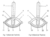
- the gearbox is part of a circuit breaker that is used in a metal-enclosed, gas-insulated switchgear and can establish connections between two of several arbitrary system components or break these connections, such as between a circuit breaker and any two busbars, between the two busbars or between the two Circuit breaker and an earth contact.
- the control discs carry one or two guide curves, which function the force given off by the levers forward the angular position of the drive shaft to the moving contact.
- control disc points in the direction of the switching point axis extended slot on.
- the drive shaft is guided through this slot and guides the control disc in the direction of the switching point axis. Since the Guide curves exactly to the desired movements of the moving Switch piece can be adjusted, so can also be complicated Realize motion sequences.
- the object of the invention is as set out in claim 1 based on specifying a control disc of the type mentioned, which characterized by a light construction, which an optimal dynamic of the Control disc movement enables and thus for switching drive energy to be reduced to a minimum.
- the control disc according to the invention is characterized in that it is a has low weight. This is due to the fact that the control disc in load-separated zones is divided. Highly stressed zones that during of a switching operation are exposed to large, dynamic forces hard, wear-free material, such as preferably hardened steel, built up. Low-impact zones consist of a much lighter one Material, such as aluminum or plastic in particular, which is proportionate low forces during the switching process are sufficient. A weight reduction resulting from this structure resulting advantages is the low power requirement to move the Control disc. On the one hand, this makes it possible for conventional Control disks to save costs due to the lower energy consumption, on the other hand, drive motors can be used for larger control discs can be used with constant performance.
- the control disk 1 predominantly made of a lightweight material compared to steel.
- Preferred materials are light metals based on Al or Ti, fiber-reinforced plastics, such as in particular thermosetting or thermoplastic Polymers.
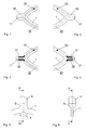
- FIGS. 1 and 2 there is a in the area of the stop 11, 21 Reinforcing element 30 made of a high-strength material. Good hardened steel is particularly suitable for this.
- the light but stable Structure of the control disc 1 enables optimal dynamics of the Control disc movement and thus reduces the effort required for switching Drive energy to a minimum.
- FIGS. 3 and 4 are only the walls of the guide curve designed as a groove in the area of the Stop 11, 21 designed with reinforcing elements 31, 32. Thereby there is a further reduction compared to the first embodiment the weight of the control disc 1.
- a preferred embodiment of the control disk 1 according to FIGS. 7 and 8 has on the back a mirror image of the first guide curve 10 second guide curve 20.
- control disc 1 To attach the control disc 1 to the movable contact piece 3 is in the Control disc 1 an adaptation element 5 according to FIG. 5 and FIG. 6 edged. On this adaptation element 5, the movable contact piece 3 is force or positively connected to the control disc 1.
Landscapes
- Engineering & Computer Science (AREA)
- General Engineering & Computer Science (AREA)
- Structural Engineering (AREA)
- Civil Engineering (AREA)
- Mechanical Engineering (AREA)
- Public Health (AREA)
- Water Supply & Treatment (AREA)
- Health & Medical Sciences (AREA)
- Hydrology & Water Resources (AREA)
- Life Sciences & Earth Sciences (AREA)
- Gears, Cams (AREA)
- Rotary Switch, Piano Key Switch, And Lever Switch (AREA)
- Friction Gearing (AREA)
- Transmission Devices (AREA)
- Mechanical Operated Clutches (AREA)
- Braking Arrangements (AREA)
Abstract
Description
Das Getriebe ist Teil eines Trennschalters, der in einer metallgekapselten gasisolierten Schaltanlage verwendet und je nach Bedarf zwischen zwei von mehreren beliebigen Anlagenkomponenten Verbindungen herstellen oder diese Verbindungen auftrennen kann, wie etwa zwischen einem Leistungsschalter und einer beliebigen zweier Sammelschienen, zwischen den beiden Sammelschienen oder zwischen dem Leistungsschalter und einem Erdungskontakt.
- 1
- Steuerscheibe
- 2
- Antriebswelle
- 3
- bewegliches Schaltstück
- 4
- Langloch
- 5
- Adaptionselement
- 10, 20
- Führungskurven
- 11, 21
- Anschlagstellen
- 12, 13, 22, 23
- Kurvenabschnitte
- 15, 25
- Führungsteile
- 30, 31, 32
- Verstärkungselemente
Claims (10)
- Steuerscheibe (1) für ein Kraft von einer Antriebswelle (2) auf ein bewegliches Schaltstück (3) übertragendes Getriebe eines Trennschalters, die mit dem beweglichen Schaltstück (3) fest verbunden, quer zur Antriebswelle (2) ausgerichtet und verschiebbar ist,
und die mit mindestens einem an der Antriebswelle (2) befestigten Hebel derart zusammenwirkt, dass ein am Hebel befestigtes Führungsteil (15) durch Drehen der Welle (2) in einer in der Steuerscheibe (1) als Nut eingelassenen ersten Führungskurve (10) aus zwei im wesentlichen kreisbogenförmig ausgebildeten, in eine Anschlagstelle (11) für das Führungsteil (15) auslaufenden Abschnitten (12, 13) Kraft auf die Steuerscheibe (1) ausübt, dadurch gekennzeichnet, dass die Steuerscheibe (1) vorwiegend aus einem Basismaterial besteht, das leichter ist als Stahl, und dass an der Anschlagstelle (11) ein erstes Verstärkungselement (30, 31, 32) aus einem hochfesten Werkstoff vorgesehen ist. - Steuerscheibe (1) nach Anspruch 1, dadurch gekennzeichnet, dass eine als Nut eingelassene zweite Führungskurve (20) auf der Rückseite der Steuerscheibe spiegelverkehrt gegenüber der ersten Führungskurve (10) angebracht ist, und dass an der Anschlagstelle (21) zwischen den zwei im wesentlichen kreisbogenförmig ausgebildeten Abschnitten (22, 23) der zweiten Führungskurve (20) ein zweites Verstärkungselement (30, 31, 32) aus einem hochfesten Werkstoff vorgesehen ist.
- Steuerscheibe (1) nach einem der Ansprüche 1 oder 2, dadurch gekennzeichnet, dass das erste und/ oder zweite Verstärkungselement (30, 31, 32) aus thermisch behandeltem Stahl gefertigt sind.
- Steuerscheibe (1) nach einem der Ansprüche 1 bis 3, dadurch gekennzeichnet, dass die Steuerscheibe (1) vorwiegend aus Aluminium, Kunststoff oder Blech gefertigt ist.
- Steuerscheibe (1) nach einem der Ansprüche 1 bis 4, dadurch gekennzeichnet, dass das Verstärkungselement (31, 32) lediglich an einer oberen und unteren Wand der Anschlagstelle (11, 21) der Führungskurve (10, 20) in die Steuerscheibe (1) eingepasst ist.
- Steuerscheibe (1) nach einem der Ansprüche 1 bis 5, dadurch gekennzeichnet, dass das Verstärkungselement (30, 31, 32) kraftschlüssig mit dem Basismaterial verbunden ist.
- Steuerscheibe (1) nach einem der Ansprüche 1 bis 5, dadurch gekennzeichnet, dass das Verstärkungselement (30, 31, 32) mit dem Basismaterial formschlüssig verbunden ist.
- Steuerscheibe (1) nach einem der Ansprüche 1 bis 7, dadurch gekennzeichnet, dass in das Basismaterial ein Adaptionselement (5) zum Befestigen des beweglichen Schaltstücks eingefasst ist.
- Verfahren zur Herstellung einer Steuerscheibe (1) nach Anspruch 6, dadurch gekennzeichnet, dass das Verstärkungselement (30, 31, 32) durch Verschrauben, Verstiften, Kleben, Löten, Reibschweissen, Schweissen oder Sintern mit dem Basismaterial verbunden ist.
- Verfahren zur Herstellung einer Steuerscheibe (1) nach Anspruch 7, dadurch gekennzeichnet, dass das Verstärkungselement (30, 31, 32) während der Formung der Steuerscheibe (1) durch Eingiessen mit dem Basismaterial formschlüssig verbunden wird.
Applications Claiming Priority (2)
| Application Number | Priority Date | Filing Date | Title |
|---|---|---|---|
| DE19907887A DE19907887A1 (de) | 1999-02-24 | 1999-02-24 | Steuerscheibe für Getriebe eines Trennschalters und ein Verfahren zur Herstellung einer solchen Steuerscheibe |
| DE19907887 | 1999-02-24 |
Publications (2)
| Publication Number | Publication Date |
|---|---|
| EP1032002A2 true EP1032002A2 (de) | 2000-08-30 |
| EP1032002A3 EP1032002A3 (de) | 2001-05-09 |
Family
ID=7898648
Family Applications (1)
| Application Number | Title | Priority Date | Filing Date |
|---|---|---|---|
| EP00810070A Withdrawn EP1032002A3 (de) | 1999-02-24 | 2000-01-26 | Steuerscheibe für Getriebe eines Trennschalters und ein Verfahren zur Herstellung einer solchen Steuerscheibe |
Country Status (5)
| Country | Link |
|---|---|
| EP (1) | EP1032002A3 (de) |
| JP (1) | JP2000251593A (de) |
| KR (1) | KR20000076684A (de) |
| CN (1) | CN1264907A (de) |
| DE (1) | DE19907887A1 (de) |
Families Citing this family (1)
| Publication number | Priority date | Publication date | Assignee | Title |
|---|---|---|---|---|
| EP3179496B1 (de) | 2015-12-10 | 2018-08-22 | ABB Schweiz AG | Rotierende hilfsschalter für mittelspannungsschaltanlagen |
Family Cites Families (6)
| Publication number | Priority date | Publication date | Assignee | Title |
|---|---|---|---|---|
| DE2136213A1 (de) * | 1971-07-20 | 1973-02-08 | Transformatoren Union Ag | Getriebe fuer stufenschalter von stufentransformatoren |
| DE2949753A1 (de) * | 1979-12-07 | 1981-06-11 | Siemens AG, 1000 Berlin und 8000 München | Hochspannungs-leistungsschalter |
| CH652857A5 (en) * | 1980-11-24 | 1985-11-29 | Sprecher & Schuh Ag | High-voltage switch |
| US5475190A (en) * | 1994-04-15 | 1995-12-12 | Eaton Corporation | Operator of a handle or toggle of a switch |
| DE19511168A1 (de) * | 1995-03-28 | 1996-10-02 | Abb Management Ag | Schaltvorrichtung |
| DE19615912A1 (de) * | 1996-04-22 | 1997-10-23 | Asea Brown Boveri | Trennschalter |
-
1999
- 1999-02-24 DE DE19907887A patent/DE19907887A1/de not_active Withdrawn
-
2000
- 2000-01-26 EP EP00810070A patent/EP1032002A3/de not_active Withdrawn
- 2000-02-17 KR KR1020000007531A patent/KR20000076684A/ko not_active Withdrawn
- 2000-02-22 CN CN00103046A patent/CN1264907A/zh active Pending
- 2000-02-23 JP JP2000046264A patent/JP2000251593A/ja not_active Withdrawn
Also Published As
| Publication number | Publication date |
|---|---|
| CN1264907A (zh) | 2000-08-30 |
| EP1032002A3 (de) | 2001-05-09 |
| JP2000251593A (ja) | 2000-09-14 |
| KR20000076684A (ko) | 2000-12-26 |
| DE19907887A1 (de) | 2000-08-31 |
Similar Documents
| Publication | Publication Date | Title |
|---|---|---|
| DE2829433C2 (de) | Schraubengetriebe | |
| DE19543645B4 (de) | Vorrichtung zum Schalten von sperrsynchronisierten Fahrzeuggetrieben | |
| EP2034384A2 (de) | Pedalanordnung zur Betätigung einer Kupplung | |
| DE3824296A1 (de) | Vorrichtung zum schalten eines kraftfahrzeuggetriebes | |
| DE19535667C2 (de) | Verstellvorrichtung für einen Fahrzeugscheinwerfer | |
| EP0460485A1 (de) | Getriebe zur Überführung einer rotatorischen in eine translatorische Bewegung | |
| EP1097657B1 (de) | Teleskopantriebseinheit | |
| DE68910890T2 (de) | Mechanismus und dessen arbeitsweise zum positionieren eines gangschalthebels in parkstellung. | |
| DE3839319C2 (de) | ||
| EP4129756B1 (de) | Linearantrieb, längsverstellvorrichtung eines sitzes und kraftfahrzeug | |
| EP1531290B1 (de) | Schalteinrichtung | |
| DE102008059163B4 (de) | Rüttelfester Verfahrantrieb für ein Schaltgerät sowie Schaltgeräte mit einem derartigen Verfahrantrieb | |
| EP1870617A2 (de) | Betätigungseinrichtung für ein Getriebe eines Fahrzeugs | |
| EP1032002A2 (de) | Steuerscheibe für Getriebe eines Trennschalters und ein Verfahren zur Herstellung einer solchen Steuerscheibe | |
| DE69620340T2 (de) | Vorrichtung zum wohlweisen Erzeugen von gewünschten Darstellungen | |
| DE3613480C2 (de) | ||
| DE3726801A1 (de) | Kraftuebertragungseinrichtung | |
| DE60303772T2 (de) | Wählhebel für ein Kraftfahrzeug-Getriebe mit magnetischer Haltevorrichtung | |
| EP0165229B1 (de) | Vorrichtung zur Sicherung der Lage der Zungenschienen von Gleisweichen | |
| DE10347492A1 (de) | Schalteinrichtung | |
| DE4106620A1 (de) | Traegerprofil fuer einen verfahrbaren schlitten o. ae. | |
| DE10227730C1 (de) | Verstellantrieb für Kraftfahrzeugsitzteile | |
| WO1995034114A1 (de) | Schaltgerät mit einer einrichtung zum einfahren in eine schaltzelle | |
| DE19742573C2 (de) | Getriebebetätigungsvorrichtung | |
| DE1804463C3 (de) | Mikroskop |
Legal Events
| Date | Code | Title | Description |
|---|---|---|---|
| PUAI | Public reference made under article 153(3) epc to a published international application that has entered the european phase |
Free format text: ORIGINAL CODE: 0009012 |
|
| AK | Designated contracting states |
Kind code of ref document: A2 Designated state(s): AT BE CH CY DE DK ES FI FR GB GR IE IT LI LU MC NL PT SE |
|
| AX | Request for extension of the european patent |
Free format text: AL;LT;LV;MK;RO;SI |
|
| PUAL | Search report despatched |
Free format text: ORIGINAL CODE: 0009013 |
|
| STAA | Information on the status of an ep patent application or granted ep patent |
Free format text: STATUS: THE APPLICATION HAS BEEN WITHDRAWN |
|
| AK | Designated contracting states |
Kind code of ref document: A3 Designated state(s): AT BE CH CY DE DK ES FI FR GB GR IE IT LI LU MC NL PT SE |
|
| AX | Request for extension of the european patent |
Free format text: AL;LT;LV;MK;RO;SI |
|
| 18W | Application withdrawn |
Withdrawal date: 20010321 |