EP1032002A2 - Control disc for driving a sectionaliser and process of making it - Google Patents
Control disc for driving a sectionaliser and process of making it Download PDFInfo
- Publication number
- EP1032002A2 EP1032002A2 EP00810070A EP00810070A EP1032002A2 EP 1032002 A2 EP1032002 A2 EP 1032002A2 EP 00810070 A EP00810070 A EP 00810070A EP 00810070 A EP00810070 A EP 00810070A EP 1032002 A2 EP1032002 A2 EP 1032002A2
- Authority
- EP
- European Patent Office
- Prior art keywords
- control disc
- control
- reinforcing element
- guide curve
- disc
- Prior art date
- Legal status (The legal status is an assumption and is not a legal conclusion. Google has not performed a legal analysis and makes no representation as to the accuracy of the status listed.)
- Withdrawn
Links
- 238000000034 method Methods 0.000 title description 3
- 239000000463 material Substances 0.000 claims abstract description 13
- 230000003014 reinforcing effect Effects 0.000 claims description 15
- 238000004519 manufacturing process Methods 0.000 claims description 7
- 230000006978 adaptation Effects 0.000 claims description 4
- 230000005540 biological transmission Effects 0.000 claims description 4
- 238000003466 welding Methods 0.000 claims description 4
- 229910000831 Steel Inorganic materials 0.000 claims description 3
- 229910052782 aluminium Inorganic materials 0.000 claims description 3
- 239000010959 steel Substances 0.000 claims description 3
- 238000004026 adhesive bonding Methods 0.000 claims description 2
- XAGFODPZIPBFFR-UHFFFAOYSA-N aluminium Chemical compound [Al] XAGFODPZIPBFFR-UHFFFAOYSA-N 0.000 claims description 2
- 229910052751 metal Inorganic materials 0.000 claims description 2
- 239000002184 metal Substances 0.000 claims description 2
- 239000004033 plastic Substances 0.000 claims description 2
- 229920003023 plastic Polymers 0.000 claims description 2
- 238000005245 sintering Methods 0.000 claims description 2
- 238000005476 soldering Methods 0.000 claims description 2
- 230000033001 locomotion Effects 0.000 abstract description 5
- 241001136792 Alle Species 0.000 description 6
- 229910000760 Hardened steel Inorganic materials 0.000 description 2
- 229920002430 Fibre-reinforced plastic Polymers 0.000 description 1
- 239000000853 adhesive Substances 0.000 description 1
- 230000001070 adhesive effect Effects 0.000 description 1
- 230000015572 biosynthetic process Effects 0.000 description 1
- 238000010276 construction Methods 0.000 description 1
- 238000004132 cross linking Methods 0.000 description 1
- 230000000694 effects Effects 0.000 description 1
- 238000005265 energy consumption Methods 0.000 description 1
- 239000011151 fibre-reinforced plastic Substances 0.000 description 1
- 239000003562 lightweight material Substances 0.000 description 1
- 150000002739 metals Chemical class 0.000 description 1
- 229920001169 thermoplastic Polymers 0.000 description 1
- 229920001187 thermosetting polymer Polymers 0.000 description 1
- 239000013585 weight reducing agent Substances 0.000 description 1
Images
Classifications
-
- H—ELECTRICITY
- H01—ELECTRIC ELEMENTS
- H01H—ELECTRIC SWITCHES; RELAYS; SELECTORS; EMERGENCY PROTECTIVE DEVICES
- H01H3/00—Mechanisms for operating contacts
- H01H3/32—Driving mechanisms, i.e. for transmitting driving force to the contacts
- H01H3/42—Driving mechanisms, i.e. for transmitting driving force to the contacts using cam or eccentric
-
- E—FIXED CONSTRUCTIONS
- E02—HYDRAULIC ENGINEERING; FOUNDATIONS; SOIL SHIFTING
- E02B—HYDRAULIC ENGINEERING
- E02B13/00—Irrigation ditches, i.e. gravity flow, open channel water distribution systems
-
- E—FIXED CONSTRUCTIONS
- E02—HYDRAULIC ENGINEERING; FOUNDATIONS; SOIL SHIFTING
- E02B—HYDRAULIC ENGINEERING
- E02B5/00—Artificial water canals, e.g. irrigation canals
- E02B5/02—Making or lining canals
-
- E—FIXED CONSTRUCTIONS
- E03—WATER SUPPLY; SEWERAGE
- E03F—SEWERS; CESSPOOLS
- E03F5/00—Sewerage structures
- E03F5/04—Gullies inlets, road sinks, floor drains with or without odour seals or sediment traps
- E03F5/06—Gully gratings
-
- H—ELECTRICITY
- H01—ELECTRIC ELEMENTS
- H01H—ELECTRIC SWITCHES; RELAYS; SELECTORS; EMERGENCY PROTECTIVE DEVICES
- H01H31/00—Air-break switches for high tension without arc-extinguishing or arc-preventing means
- H01H31/26—Air-break switches for high tension without arc-extinguishing or arc-preventing means with movable contact that remains electrically connected to one line in open position of switch
- H01H31/32—Air-break switches for high tension without arc-extinguishing or arc-preventing means with movable contact that remains electrically connected to one line in open position of switch with rectilinearly-movable contact
Definitions
- the invention is based on a control disk for a transmission according to the preamble of claim 1.
- the invention also relates to a method for producing such a control disk.
- the gearbox is part of a circuit breaker that is used in a metal-enclosed, gas-insulated switchgear and can establish connections between two of several arbitrary system components or break these connections, such as between a circuit breaker and any two busbars, between the two busbars or between the two Circuit breaker and an earth contact.
- the control discs carry one or two guide curves, which function the force given off by the levers forward the angular position of the drive shaft to the moving contact.
- control disc points in the direction of the switching point axis extended slot on.
- the drive shaft is guided through this slot and guides the control disc in the direction of the switching point axis. Since the Guide curves exactly to the desired movements of the moving Switch piece can be adjusted, so can also be complicated Realize motion sequences.
- the object of the invention is as set out in claim 1 based on specifying a control disc of the type mentioned, which characterized by a light construction, which an optimal dynamic of the Control disc movement enables and thus for switching drive energy to be reduced to a minimum.
- the control disc according to the invention is characterized in that it is a has low weight. This is due to the fact that the control disc in load-separated zones is divided. Highly stressed zones that during of a switching operation are exposed to large, dynamic forces hard, wear-free material, such as preferably hardened steel, built up. Low-impact zones consist of a much lighter one Material, such as aluminum or plastic in particular, which is proportionate low forces during the switching process are sufficient. A weight reduction resulting from this structure resulting advantages is the low power requirement to move the Control disc. On the one hand, this makes it possible for conventional Control disks to save costs due to the lower energy consumption, on the other hand, drive motors can be used for larger control discs can be used with constant performance.
- the control disk 1 predominantly made of a lightweight material compared to steel.
- Preferred materials are light metals based on Al or Ti, fiber-reinforced plastics, such as in particular thermosetting or thermoplastic Polymers.
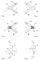
- FIGS. 1 and 2 there is a in the area of the stop 11, 21 Reinforcing element 30 made of a high-strength material. Good hardened steel is particularly suitable for this.
- the light but stable Structure of the control disc 1 enables optimal dynamics of the Control disc movement and thus reduces the effort required for switching Drive energy to a minimum.
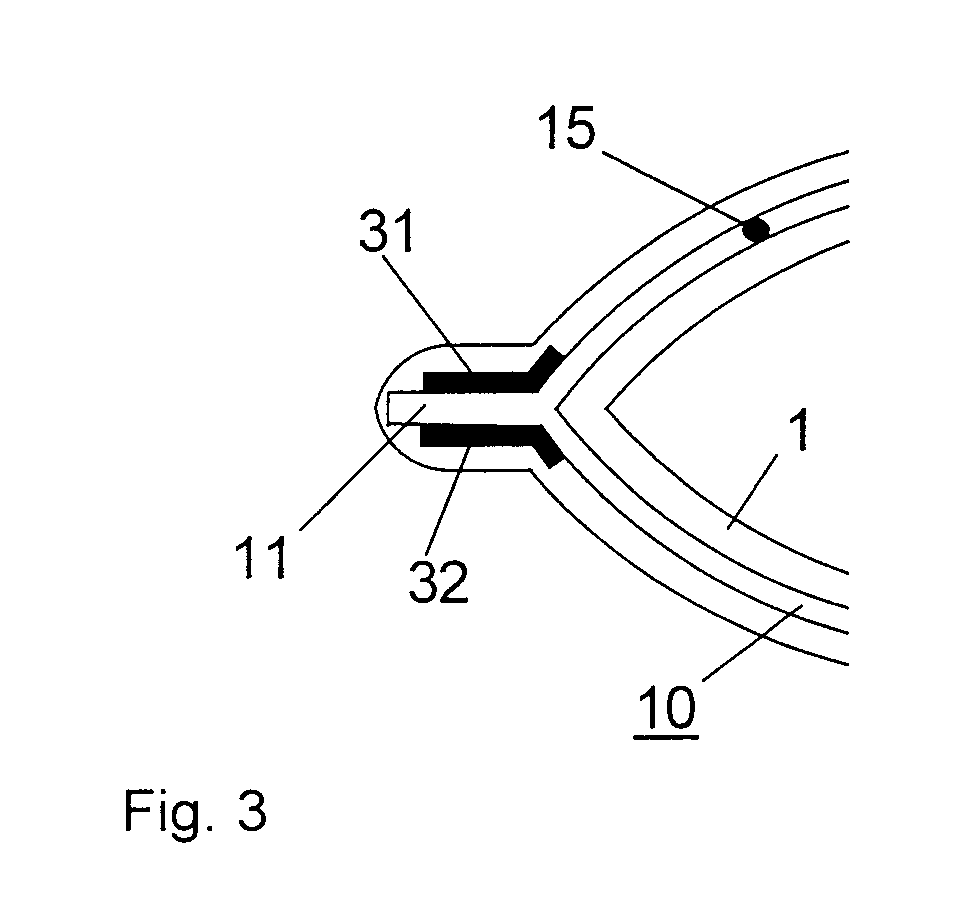
- FIGS. 3 and 4 are only the walls of the guide curve designed as a groove in the area of the Stop 11, 21 designed with reinforcing elements 31, 32. Thereby there is a further reduction compared to the first embodiment the weight of the control disc 1.
- a preferred embodiment of the control disk 1 according to FIGS. 7 and 8 has on the back a mirror image of the first guide curve 10 second guide curve 20.
- control disc 1 To attach the control disc 1 to the movable contact piece 3 is in the Control disc 1 an adaptation element 5 according to FIG. 5 and FIG. 6 edged. On this adaptation element 5, the movable contact piece 3 is force or positively connected to the control disc 1.
Landscapes
- Engineering & Computer Science (AREA)
- General Engineering & Computer Science (AREA)
- Structural Engineering (AREA)
- Civil Engineering (AREA)
- Mechanical Engineering (AREA)
- Public Health (AREA)
- Water Supply & Treatment (AREA)
- Health & Medical Sciences (AREA)
- Hydrology & Water Resources (AREA)
- Life Sciences & Earth Sciences (AREA)
- Gears, Cams (AREA)
- Rotary Switch, Piano Key Switch, And Lever Switch (AREA)
- Friction Gearing (AREA)
- Transmission Devices (AREA)
- Mechanical Operated Clutches (AREA)
- Braking Arrangements (AREA)
Abstract
Die Steuerscheibe (1) ist Teil eines Getriebes eines Trennschalters. Die Steuerscheibe (1) trägt mindestens eine Führungskurve (10). Die Führungskurve (10) besteht aus zwei kreisbogenförmigen Abschnitten, die in einer dazwischenliegenden Anschlagstelle (11) münden. Die Führungskurve (10) führt ein Führungselement (15), welches über einen Hebel mit einer Antriebswelle starr verbunden ist und über welches in Abhängigkeit von Drehsinn und Winkelposition der Antriebsachse Kraft auf die Steuerscheibe (1) übertragen wird.The control disc (1) is part of a gearbox of a disconnector. The Control disc (1) carries at least one guide curve (10). The leadership curve (10) consists of two sections in the shape of a circular arc, which are in one open the stop point (11) in between. The guide curve (10) leads a guide element (15) which is connected to a drive shaft via a lever is rigidly connected and via which depending on the direction of rotation and Transfer the angular position of the drive axle to the control disc (1) becomes.
Die während einem Schaltvorgang schwach belasteten Zonen der Steuerscheibe (1) sind aus einem wesentlich leichteren Material ausgebildet als die hochbelasteten Zonen (31, 32) im Bereich der Anschlagstelle (11).The zones of the control disc that are weakly loaded during a switching operation (1) are made of a much lighter material than that highly stressed zones (31, 32) in the area of the anchor point (11).
Die daraus resultierende leichte Bauweise ermöglicht eine optimale Dynamik der
Steuerscheibenbewegung und reduziert damit die zum Schalten benötigte
Antriebsenergie auf ein Minimum.
Description
Bei der Erfindung wird ausgegangen von einer Steuerscheibe für ein Getriebe
nach dem Oberbegriff von Patentanspruch 1. Die Erfindung betrifft auch ein
Verfahren zur Herstellung einer solchen Steuerscheibe.
Das Getriebe ist Teil eines Trennschalters, der in einer metallgekapselten
gasisolierten Schaltanlage verwendet und je nach Bedarf zwischen zwei von
mehreren beliebigen Anlagenkomponenten Verbindungen herstellen oder diese
Verbindungen auftrennen kann, wie etwa zwischen einem Leistungsschalter und
einer beliebigen zweier Sammelschienen, zwischen den beiden Sammelschienen
oder zwischen dem Leistungsschalter und einem Erdungskontakt.The invention is based on a control disk for a transmission according to the preamble of
The gearbox is part of a circuit breaker that is used in a metal-enclosed, gas-insulated switchgear and can establish connections between two of several arbitrary system components or break these connections, such as between a circuit breaker and any two busbars, between the two busbars or between the two Circuit breaker and an earth contact.
Eine Steuerscheibe der eingangs erwähnten Art wird in der Offenlegungsschrift DE 196 15 912 A1 beschrieben. Das in dieser Schrift beschriebene Getriebe für einen Trennschalter mit mindestens einer Schaltstelle mit einem feststehenden und einem längs der Schaltstellenachse beweglichen Schaltstück und einer Antriebswelle, enthält in das bewegliche Schaltstücke integrierte Steuerscheiben und an der Antriebswelle befestigte Hebel. Die Steuerscheiben tragen eine oder zwei Führungskurven, welche die von den Hebeln abgegebene Kraft in Funktion der Winkelposition der Antriebswelle an das bewegliche Schaltstück weiterleiten. A control disk of the type mentioned in the opening paragraph DE 196 15 912 A1. The gearbox described in this document for a disconnector with at least one switching point with a fixed one and a switching piece movable along the switching point axis and one Drive shaft, contains control disks integrated in the moving contact pieces and levers attached to the drive shaft. The control discs carry one or two guide curves, which function the force given off by the levers forward the angular position of the drive shaft to the moving contact.
Zudem weist die Steuerscheibe ein in Richtung der Schaltstellenachse erstrecktes Langloch auf. Die Antriebswelle ist durch dieses Langloch geführt und führt die Steuerscheibe in Richtung der Schaltstellenachse. Da die Führungskurven exakt an die erwünschten Bewegungsabläufe des beweglichen Schaltstücks angepasst werden können, lassen sich so auch komplizierte Bewegungsabläufe realisieren.In addition, the control disc points in the direction of the switching point axis extended slot on. The drive shaft is guided through this slot and guides the control disc in the direction of the switching point axis. Since the Guide curves exactly to the desired movements of the moving Switch piece can be adjusted, so can also be complicated Realize motion sequences.
Der Erfindung, wie sie im Patentanspruch 1 angegeben ist, liegt die Aufgabe
zugrunde, eine Steuerscheibe der eingangs genannten Art anzugeben, die sich
durch eine leichte Bauweise auszeichnet, die eine optimale Dynamik der
Steuerscheibenbewegung ermöglicht und damit die zum Schalten
aufzuwendende Antriebsenergie auf ein Minimum reduzieren lässt.The object of the invention is as set out in
Die Steuerscheibe nach der Erfindung zeichnet sich dadurch aus, dass sie ein geringes Gewicht aufweist. Dies ist dadurch bedingt, dass die Steuerscheibe in belastungsgetrennte Zonen aufgeteilt ist. Hochbelastete Zonen, die während eines Schaltvorgangs grossen, dynamischen Kräften ausgesetzt sind, sind aus hartem, abnutzungsfreiem Material, wie vorzugsweise gehärteter Stahl, aufgebaut. Schwachbelastete Zonen bestehen aus einem wesentlich leichteren Material, wie insbesondere Aluminium oder Kunststoff, das den verhältnismässig geringen Kräften während dem Schaltvorgang ohne weiteres genügt. Ein aus der aus diesem Aufbau hervorgehenden Gewichtsreduktion resultierenden Vorteile liegt beim geringen Leistungsbedarf zum Bewegen der Steuerscheibe. Damit wird es einerseits möglich, für herkömmliche Steuerscheiben aufgrund des geringeren Energieaufwands Kosten zu sparen, andererseits können für grösser dimensionierte Steuerscheiben Antriebsmotoren mit gleichbleibender Leistung verwendet werden. The control disc according to the invention is characterized in that it is a has low weight. This is due to the fact that the control disc in load-separated zones is divided. Highly stressed zones that during of a switching operation are exposed to large, dynamic forces hard, wear-free material, such as preferably hardened steel, built up. Low-impact zones consist of a much lighter one Material, such as aluminum or plastic in particular, which is proportionate low forces during the switching process are sufficient. A weight reduction resulting from this structure resulting advantages is the low power requirement to move the Control disc. On the one hand, this makes it possible for conventional Control disks to save costs due to the lower energy consumption, on the other hand, drive motors can be used for larger control discs can be used with constant performance.
Bevorzugte Ausführungsbeispiele der Erfindung und die damit erzielbaren
weiteren Vorteile werden nachfolgend anhand von Zeichnungen näher erläutert.
Hierbei zeigt:
In allen Figuren bezeichnen gleiche Bezugszeichen gleichwirkende Teile.
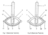
Die in Fig. 7 und Fig. 8 dargestellten, aus der obengenannten Druckschrift DE
196 15 912 A1 bekannten Steuerscheiben 1 werden in einem Getriebe eines
Trennschalters eingesetzt. An der Steuerscheibe 1 ist ein bewegliches
Schaltstück 3 befestigt. Eine Antriebsachse 2 ist durch ein Langloch 4 in der
Steuerscheibe geführt. Ein Führungsteil 15, 25 ist über einen Hebel fest mit der
Antriebsachse 2 verbunden. In der Steuerscheibe 1 ist auf einer Seite eine
Führungskurve 10, 20 als Nut eingelassen. Die Führungskurve 10, 20 setzt sich
aus zwei im wesentlichen kreisbogenförmig ausgebildeten Abschnitten 12, 13,
22, 23 zusammen, die in einer Anschlagstelle 11, 21 für das in der
Führungskurve 10,20 angreifende Führungsteil 15, 25 auslaufen.
Durch Drehen an der Antriebsachse 2 wird das Führungsteil 15, 25 in der
Führungskurve 10, 20 bewegt. Je nach Drehsinn und Winkelposition der
Antriebsachse 2 übt das Führungsteil 15, 25 im Bereich der Anschlagstelle 11,
21 der Führungskurve 10, 20 eine Kraft auf die Steuerscheibe 1 aus.In all figures, the same reference numerals designate parts with the same effect.
The shown in Fig. 7 and Fig. 8, from the above publication DE
196 15 912 A1 known
In einer ersten Ausführungsform nach der Erfindung ist die Steuerscheibe 1
vorwiegend aus einem im Vergleich zu Stahl leichten Material aufgebaut.
Bevorzugte Materiale sind Leichtmetalle auf der Basis von Al oder Ti,
fasernverstärkte Kunsstoffe, wie insbesondere duro- oder thermoplastische
Polymere. Im Bereich der Anschlagstelle 11, 21 ist gemäss Fig. 1 und Fig. 2 ein
Verstärkungselement 30 aus einem hochfesten Werkstoff vorgesehen. Gut
geeignet dafür ist insbesondere gehärteter Stahl. Der leichte und dennoch stabile
Aufbau der Steuerscheibe 1 ermöglicht eine optimale Dynamik der
Steuerscheibenbewegung und reduziert somit die zum Schalten aufzuwendende
Antriebsenerergie auf ein Minimum.In a first embodiment according to the invention, the
In einer weiteren Ausführungsform nach der Erfindung gemäss Fig. 3 und Fig. 4
sind nur die Wände der als Nut ausgebildeten Führungskurve im Bereich der
Anschlagstelle 11, 21 mit Verstärkungselementen 31, 32 ausgelegt. Dadurch
kommt es gegenüber der ersten Ausführungform zu einer weiteren Reduktion
des Gewichts der Steuerscheibe 1.In a further embodiment according to the invention according to FIGS. 3 and 4
are only the walls of the guide curve designed as a groove in the area of the
Eine bevorzugte Ausführungsform der Steuerscheibe 1 gemäss Fig. 7 und Fig. 8
weist auf der Rückseite eine zur ersten Führungskurve 10 spiegelverkehrte
zweite Führungskurve 20 auf.A preferred embodiment of the
Zur Befestigung der Steuerscheibe 1 an dem beweglichen Schaltstück 3 ist in der
Steuerscheibe 1 ein Adaptionselement 5 gemäss Fig. 5 und Fig. 6 eingefasst. An
diesem Adaptionselement 5 wird das bewegliche Schaltstück 3 kraft- oder
formschlüssig mit der Steuerscheibe 1 verbunden.To attach the
In einem ersten Verfahren zur Herstellung einer Steuerscheibe 1 nach der
Erfindung werden die Verstärkungselemente 30, 31, 32 im Bereich der
Anschlagstelle 11, 21 mit Schrauben oder Stiften kraftschlüssig mit der
Steuerscheibe 1 verbunden.In a first method for producing a
In einem zweiten Verfahren zur Herstellung einer Steuerscheibe 1 nach der
Erfindung werden die Verstärkungselemente 30, 31, 32 im Bereich der
Anschlagstelle 11, 21 adhäsiv durch Kleben oder Löten mit der Steuerscheibe 1
verbunden. In a second method for producing a
In einem dritten Verfahren zur Herstellung einer Steuerscheibe 1 nach der
Erfindung werden die Verstärkungselemente 30, 31, 32 im Bereich der
Anschlagstelle 11, 21 durch Reibschweissen, Sintern oder Schweissen
kraftschlüssig mit der Steuerscheibe 1 verbunden. Bei diesem Verfahren werden
die Festigkeit der Verbindung erhöhende (teil-)kristalline/ (teil-)vernetzende
Werkstoffstrukturen erzeugt.In a third method for producing a
In einem vierten Verfahren zur Herstellung einer Steuerscheibe 1 nach der
Erfindung werden die Verstärkungselemente 30, 31, 32 im Bereich der
Anschlagstelle 11, 21 während der Formung der Steuerscheibe 1 mit dieser
durch Eingiessen formschlüssig verbunden.In a fourth method for producing a
- 11
- SteuerscheibeControl disc
- 22nd
- Antriebswelledrive shaft
- 33rd
- bewegliches Schaltstückmovable contact
- 44th
- LanglochLong hole
- 55
- AdaptionselementAdaptation element
- 10, 2010, 20
- FührungskurvenLeadership curves
- 11, 2111, 21
- AnschlagstellenAnchor points
- 12, 13, 22, 2312, 13, 22, 23
- KurvenabschnitteCurve sections
- 15, 2515, 25
- FührungsteileGuide parts
- 30, 31, 3230, 31, 32
- VerstärkungselementeReinforcing elements
Claims (10)
und die mit mindestens einem an der Antriebswelle (2) befestigten Hebel derart zusammenwirkt, dass ein am Hebel befestigtes Führungsteil (15) durch Drehen der Welle (2) in einer in der Steuerscheibe (1) als Nut eingelassenen ersten Führungskurve (10) aus zwei im wesentlichen kreisbogenförmig ausgebildeten, in eine Anschlagstelle (11) für das Führungsteil (15) auslaufenden Abschnitten (12, 13) Kraft auf die Steuerscheibe (1) ausübt, dadurch gekennzeichnet, dass die Steuerscheibe (1) vorwiegend aus einem Basismaterial besteht, das leichter ist als Stahl, und dass an der Anschlagstelle (11) ein erstes Verstärkungselement (30, 31, 32) aus einem hochfesten Werkstoff vorgesehen ist.Control disk (1) for a transmission of a disconnector which transmits force from a drive shaft (2) to a movable switching element (3) and which is firmly connected to the movable switching element (3), aligned transversely to the drive shaft (2) and displaceable,
and which cooperates with at least one lever fastened to the drive shaft (2) in such a way that a guide part (15) fastened to the lever by rotating the shaft (2) in a first guide curve (10) made as a groove in the control disk (1) consists of two Essentially circular-arcuate sections (12, 13) exiting into a stop point (11) for the guide part (15) exerts force on the control disk (1), characterized in that the control disk (1) consists predominantly of a base material which is lighter is steel and that a first reinforcing element (30, 31, 32) made of a high-strength material is provided at the stop point (11).
Applications Claiming Priority (2)
| Application Number | Priority Date | Filing Date | Title |
|---|---|---|---|
| DE19907887A DE19907887A1 (en) | 1999-02-24 | 1999-02-24 | Control disc for gearbox of a disconnector and a method for producing such a control disc |
| DE19907887 | 1999-02-24 |
Publications (2)
| Publication Number | Publication Date |
|---|---|
| EP1032002A2 true EP1032002A2 (en) | 2000-08-30 |
| EP1032002A3 EP1032002A3 (en) | 2001-05-09 |
Family
ID=7898648
Family Applications (1)
| Application Number | Title | Priority Date | Filing Date |
|---|---|---|---|
| EP00810070A Withdrawn EP1032002A3 (en) | 1999-02-24 | 2000-01-26 | Control disc for driving a sectionaliser and process of making it |
Country Status (5)
| Country | Link |
|---|---|
| EP (1) | EP1032002A3 (en) |
| JP (1) | JP2000251593A (en) |
| KR (1) | KR20000076684A (en) |
| CN (1) | CN1264907A (en) |
| DE (1) | DE19907887A1 (en) |
Families Citing this family (1)
| Publication number | Priority date | Publication date | Assignee | Title |
|---|---|---|---|---|
| EP3179496B1 (en) | 2015-12-10 | 2018-08-22 | ABB Schweiz AG | Rotary auxiliary switches for medium voltage switchgears |
Family Cites Families (6)
| Publication number | Priority date | Publication date | Assignee | Title |
|---|---|---|---|---|
| DE2136213A1 (en) * | 1971-07-20 | 1973-02-08 | Transformatoren Union Ag | GEARBOX FOR TAP SWITCHES OF TAPPING TRANSFORMERS |
| DE2949753A1 (en) * | 1979-12-07 | 1981-06-11 | Siemens AG, 1000 Berlin und 8000 München | HIGH VOLTAGE CIRCUIT BREAKERS |
| CH652857A5 (en) * | 1980-11-24 | 1985-11-29 | Sprecher & Schuh Ag | High-voltage switch |
| US5475190A (en) * | 1994-04-15 | 1995-12-12 | Eaton Corporation | Operator of a handle or toggle of a switch |
| DE19511168A1 (en) * | 1995-03-28 | 1996-10-02 | Abb Management Ag | Switching device |
| DE19615912A1 (en) * | 1996-04-22 | 1997-10-23 | Asea Brown Boveri | Disconnector |
-
1999
- 1999-02-24 DE DE19907887A patent/DE19907887A1/en not_active Withdrawn
-
2000
- 2000-01-26 EP EP00810070A patent/EP1032002A3/en not_active Withdrawn
- 2000-02-17 KR KR1020000007531A patent/KR20000076684A/en not_active Withdrawn
- 2000-02-22 CN CN00103046A patent/CN1264907A/en active Pending
- 2000-02-23 JP JP2000046264A patent/JP2000251593A/en not_active Withdrawn
Also Published As
| Publication number | Publication date |
|---|---|
| CN1264907A (en) | 2000-08-30 |
| EP1032002A3 (en) | 2001-05-09 |
| JP2000251593A (en) | 2000-09-14 |
| KR20000076684A (en) | 2000-12-26 |
| DE19907887A1 (en) | 2000-08-31 |
Similar Documents
| Publication | Publication Date | Title |
|---|---|---|
| DE2829433C2 (en) | Helical gear | |
| DE19543645B4 (en) | Device for switching lock-synchronized vehicle transmissions | |
| EP2034384A2 (en) | Pedal assembly for actuating a clutch | |
| DE3824296A1 (en) | DEVICE FOR SWITCHING A MOTOR VEHICLE TRANSMISSION | |
| DE19535667C2 (en) | Adjustment device for a vehicle headlight | |
| EP0460485A1 (en) | Transmission for converting rotary into translational movement | |
| EP1097657B1 (en) | Telescopic driving unit | |
| DE68910890T2 (en) | MECHANISM AND ITS FUNCTIONING FOR POSITIONING A GEAR SHIFT LEVER IN PARKING POSITION. | |
| DE3839319C2 (en) | ||
| EP4129756B1 (en) | Linear actuator, longitudinal adjustment device of a seat and motor vehicle | |
| EP1531290B1 (en) | Gear selector device | |
| DE102008059163B4 (en) | Shatter-proof travel drive for a switching device as well as switching devices with such a travel drive | |
| EP1870617A2 (en) | Actuating device for the transmission of a vehicle | |
| EP1032002A2 (en) | Control disc for driving a sectionaliser and process of making it | |
| DE69620340T2 (en) | Device for the wise generation of desired representations | |
| DE3613480C2 (en) | ||
| DE3726801A1 (en) | FORCE TRANSMISSION DEVICE | |
| DE60303772T2 (en) | Selector lever for a motor vehicle transmission with magnetic holding device | |
| EP0165229B1 (en) | Switch point security device for railway points | |
| DE10347492A1 (en) | switching device | |
| DE4106620A1 (en) | Support section for movable side carriage - has extruded profiled section with hard profiled rod engaging in groove | |
| DE10227730C1 (en) | Setting drive for seat parts has first spindle nut turned by drive element and both threaded sectors with end stops for spindle nut | |
| WO1995034114A1 (en) | Switching device with a mechanism for insertion into a switchgear cell | |
| DE19742573C2 (en) | Gearbox operating device | |
| DE1804463C3 (en) | microscope |
Legal Events
| Date | Code | Title | Description |
|---|---|---|---|
| PUAI | Public reference made under article 153(3) epc to a published international application that has entered the european phase |
Free format text: ORIGINAL CODE: 0009012 |
|
| AK | Designated contracting states |
Kind code of ref document: A2 Designated state(s): AT BE CH CY DE DK ES FI FR GB GR IE IT LI LU MC NL PT SE |
|
| AX | Request for extension of the european patent |
Free format text: AL;LT;LV;MK;RO;SI |
|
| PUAL | Search report despatched |
Free format text: ORIGINAL CODE: 0009013 |
|
| STAA | Information on the status of an ep patent application or granted ep patent |
Free format text: STATUS: THE APPLICATION HAS BEEN WITHDRAWN |
|
| AK | Designated contracting states |
Kind code of ref document: A3 Designated state(s): AT BE CH CY DE DK ES FI FR GB GR IE IT LI LU MC NL PT SE |
|
| AX | Request for extension of the european patent |
Free format text: AL;LT;LV;MK;RO;SI |
|
| 18W | Application withdrawn |
Withdrawal date: 20010321 |