EP1031449A1 - Open roof for vehicle provided with a tiltable wind deflector - Google Patents
Open roof for vehicle provided with a tiltable wind deflector Download PDFInfo
- Publication number
- EP1031449A1 EP1031449A1 EP00103687A EP00103687A EP1031449A1 EP 1031449 A1 EP1031449 A1 EP 1031449A1 EP 00103687 A EP00103687 A EP 00103687A EP 00103687 A EP00103687 A EP 00103687A EP 1031449 A1 EP1031449 A1 EP 1031449A1
- Authority
- EP
- European Patent Office
- Prior art keywords
- wind deflector
- opening
- closure element
- vehicle roof
- drive
- Prior art date
- Legal status (The legal status is an assumption and is not a legal conclusion. Google has not performed a legal analysis and makes no representation as to the accuracy of the status listed.)
- Granted
Links
Images
Classifications
-
- B—PERFORMING OPERATIONS; TRANSPORTING
- B60—VEHICLES IN GENERAL
- B60J—WINDOWS, WINDSCREENS, NON-FIXED ROOFS, DOORS, OR SIMILAR DEVICES FOR VEHICLES; REMOVABLE EXTERNAL PROTECTIVE COVERINGS SPECIALLY ADAPTED FOR VEHICLES
- B60J7/00—Non-fixed roofs; Roofs with movable panels, e.g. rotary sunroofs
- B60J7/22—Wind deflectors for open roofs
Definitions
- the invention relates to a vehicle roof according to the preamble of claim 1. in particular a lifting, sliding, sliding-lifting or spoiler roof.
- Such generic vehicle roofs are for example from DE 31 37 191 C2 and DE 198 27 106 A1 known.
- the closure element is one of the lid Sunroof formed, which is arranged in the longitudinal direction of the roof by means of two parallel Drive cables, each attacking on one side of the cover, in the longitudinal direction of the roof is movable. In its closed position, the lid holds it in the direction of it Display position biased wind deflector against the biasing force in its Rest position down.
- Opening the hold-down function of the sliding cover which makes the wind deflector subsequently by its opening mechanism, which essentially consists of one on the rear End of the wind deflector articulated pivot lever, due to the effect of Preload is issued in its deployed position.
- the disadvantage here is that the wind deflector is relatively close to the closed position of the Cover, i.e. after a relatively short opening distance, completely is swung out, although this position of the wind deflector, in which he the Noise from the incoming wind at the open roof opening reduced, only when the roof opening is fully open, i.e. at complete pushed back sliding cover, is required.
- these are known Systems do not have a sufficient coupling between that of the sliding cover covered opening distance and the wind deflector provided.
- the solution according to the invention advantageously ensures that a expedient correlation between that already covered by the closure element Opening path and the degree of flare of the wind deflector is created so that the The wind deflector is only issued as far as necessary.
- the wind deflector is located at closed closure element in its rest position and the or each drive cable and the opening mechanism are designed so that the wind deflector can be opened from the Rest position only begins when the closure element in by a predetermined distance Opening direction was shifted.
- the predetermined distance is preferably about 2/3 of the maximum opening distance.
- the opening mechanism is preferably designed so that the opening movement of the Wind deflector in the area after passing the predetermined distance approximately is proportional to the further opening movement of the closure element.
- the wind deflector is preferably in with a pretensioning force Towards its rest position.
- the opening mechanism of the Wind deflector on each side includes a lever, one end of which Wind deflector is hinged and the other end of the second end of the corresponding drive cable is displaceable in the longitudinal direction of the roof.
- the second end of each drive cable is one in one roof-mounted guide coupled sled.
- the closure element is preferably the cover of a sliding, Sliding-lifting or spoiler roofs.
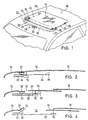
- a roof opening 12 is formed in a fixed roof skin 10, which from a sliding cover 14, which is displaceably guided in the longitudinal direction of the roof, is closed, when it is in its closed position.
- a slide 16 guided in a guide (not shown) on both sides thereof attached, at the front end of each of two on both sides of the roof opening 12 parallel compression-resistant drive cables 18 or 20 non-positively arranged attacks.
- the leading ends of the cables 18, 20 are provided with the reference symbol 22, while the outlet ends are provided with the reference number 24.
- the two Outgoing ends 24 are each displaceable in the longitudinal direction of the roof guided slide 26 provided.
- the two drive cables 18, 20 are in a known manner in its front middle section of one of a motor 28 over one of one Worm gear driven drive pinion 30 driven. 1 are the cables 18, 20 spatially arranged so that the leading ends 27 when the motor 28 is actuated and the outlet ends 24, 24 of each cable 18, 20 on the long sides of the roof opening 12 move in opposite directions.
- the cables are 18, 20 in known manner in corresponding roof-mounted cable guides (not shown) to the Guided rails.
- Wind deflector 32 is provided, which is pivotable and preferably in its front region is also slidably mounted in the vertical direction so that it can first be raised and then can be opened with its rear edge.
- the exhibition of the Wind deflector 32 takes place by means of a one indicated only schematically at 34 Opening mechanism.
- the opening mechanism comprises a spring element, by means of which the Wind deflector 32 is subjected to a biasing force to its rest position. This Preload prevents the wind deflector 32 from rattling in any position causes a closing movement of the wind deflector 32 in connection with the slides 26.
- a position is shown in which the lid 14 almost completely under the solid roof skin 10 is pushed back, i.e. the roof opening 12 is largely exposed.
- This position is at the outlet end 24 of the cable 18 or 20 attached carriage 26 moved so far forward that it engages with the Opening mechanism 34 of the wind deflector 32 occurs and by its further displacement Depending on its position, the front is raised (lifted and swung out) Wind deflector 32 causes against its bias.
- the adjustment mechanism 34 is preferably designed so that the opening of the wind deflector 32 essentially proportional to the further displacement of the carriage 26 forward, and thus approximately
- the opening mechanism 34 is proportional to the opening movement of the cover 14 can be designed for this purpose so that they have a correspondingly shaped backdrop track comprises, in which a link pin provided on the slide 26 of the outlet end 24 engages as soon as the carriage 26 has approached the wind deflector 32 accordingly. It however, solutions with ramp ramps, levers and the like are also possible.
- the distance covered by the cover 14 and thus the carriage 26 from the Can return to the closed position before the slide 26 with the opening mechanism 34 in Intervention comes and a corresponding opening of the wind deflector 32 causes is preferably about 2/3 of the maximum opening travel of the lid 14.
- the Wind deflector 32 approximately during the last third of the full opening movement of the Lid 14 fully issued.
- the sequence described above takes place in the reverse manner, i.e. the biasing force acting on the wind deflector 32 causes the Wind deflector 32 to its rest position depending on the position of the carriage 26 of the outlet end 24 of the cables 18 and 20.
- the sliding carriage 26 enables the pretensioning force a gradual lowering of the wind deflector 32.
- the wind deflector control according to the invention in a corresponding manner can also be used for sliding-lifting or spoiler roofs.
- the closure element also act as a lamella composite or a folding roof.
- the described mechanism can also be used to actuate a wind deflector slat, which is in the closed position in front of the cover 14 and covers the front part of the roof opening 12.
Abstract
Description
Die Erfindung betrifft ein Fahrzeugdach gemäß dem Oberbegriff von Anspruch 1, insbesondere ein Hebe-, Schiebe-, Schiebe-Hebe- oder Spoilerdach.The invention relates to a vehicle roof according to the preamble of claim 1. in particular a lifting, sliding, sliding-lifting or spoiler roof.
Solche gattungsgemäßen Fahrzeugdächer sind beispielsweise aus DE 31 37 191 C2 und DE 198 27 106 A1 bekannt. Dabei wird das Verschlußelement von dem Deckel eines Schiebedachs gebildet, der in Dachlängsrichtung mittels zweier parallel angeordneter Antriebskabel, die jeweils auf einer Seite des Deckels angreifen, in Dachlängsrichtung verschiebbar ist. In seiner Schließstellung hält der Deckel den in Richtung seiner Ausstellposition vorgespannten Windabweiser entgegen der Vorspannkraft in dessen Ruhestellung nieder. Beim Öffnen des Schiebedeckels endet nach einem vorbestimmten Öffnungsweg die Niederhalte-Funktion des Schiebedeckels, wodurch der Windabweiser anschließend durch seine Ausstellmechanik, die im wesentlichen aus einem an dem hinteren Ende des Windabweisers angelenkten Schwenkhebel besteht, aufgrund der Wirkung der Vorspannkraft in seine Ausstellposition ausgestellt wird.Such generic vehicle roofs are for example from DE 31 37 191 C2 and DE 198 27 106 A1 known. The closure element is one of the lid Sunroof formed, which is arranged in the longitudinal direction of the roof by means of two parallel Drive cables, each attacking on one side of the cover, in the longitudinal direction of the roof is movable. In its closed position, the lid holds it in the direction of it Display position biased wind deflector against the biasing force in its Rest position down. When opening the sliding cover ends after a predetermined Opening the hold-down function of the sliding cover, which makes the wind deflector subsequently by its opening mechanism, which essentially consists of one on the rear End of the wind deflector articulated pivot lever, due to the effect of Preload is issued in its deployed position.
Nachteilig dabei ist, daß der Windabweiser schon relativ nahe der Schließstellung des Deckels, d.h. schon nach einem relativ kurzen zurückgelegten Öffnungsweg, vollständig ausgeschwenkt wird, obwohl diese Position des Windabweisers, in welcher er die Geräuschentwicklung des anströmenden Fahrtwinds an der geöffneten Dachöffnung vermindert, erst bei vollständig geöffneter Dachöffnung, d.h. bei vollständig zurückgeschobenem Schiebedeckel, erforderlich ist. Insofern ist bei diesen bekannten Systemen keine hinreichende Kopplung zwischen dem von dem Schiebedeckel zurückgelegten Öffnungsweg und der Windabweiserstellung vorgesehen. The disadvantage here is that the wind deflector is relatively close to the closed position of the Cover, i.e. after a relatively short opening distance, completely is swung out, although this position of the wind deflector, in which he the Noise from the incoming wind at the open roof opening reduced, only when the roof opening is fully open, i.e. at complete pushed back sliding cover, is required. In this respect, these are known Systems do not have a sufficient coupling between that of the sliding cover covered opening distance and the wind deflector provided.
Es ist Aufgabe der vorliegenden Erfindung, ein öffnungsfähiges Fahrzeugdach mit einem verschiebbaren Verschlußelement und einem ausstellbaren Windabweiser zu schaffen, bei welchem der Windabweiser in Abhängigkeit von der Öffnungsstellung des Verschlußelements jeweils nur soweit als für die Fahrtwindgeräuschminderung erforderlich ausgestellt wird.It is an object of the present invention to provide an openable vehicle roof with a to create sliding closure element and an extendable wind deflector which of the wind deflectors depending on the opening position of the closure element in each case only as far as is required for the reduction of headwind noise.
Diese Aufgabe wird durch ein Fahrzeugdach gelöst, wie es in Anspruch 1 definiert ist. Vorteilhafte Ausgestaltungen der Erfindung sind den Unteransprüchen zu entnehmen.This object is achieved by a vehicle roof as defined in claim 1. Advantageous embodiments of the invention can be found in the subclaims.
Die erfindungsgemäße Lösung sorgt vorteilhaft dafür, daß auf einfache Weise eine zweckmäßige Korrelation zwischen dem von dem Verschlußelement bereits zurückgelegten Öffnungsweg und dem Ausstellgrad des Windabweisers geschaffen wird, so daß der Windabweiser jeweils nur so weit als erforderlich ausgestellt wird.The solution according to the invention advantageously ensures that a expedient correlation between that already covered by the closure element Opening path and the degree of flare of the wind deflector is created so that the The wind deflector is only issued as far as necessary.
In vorteilhafter weiterer Ausgestaltung der Erfindung befindet sich der Windabweiser bei geschlossenem Verschlußelement in seiner Ruhestellung und das bzw. jedes Antriebskabel und die Ausstellmechanik sind so ausgebildet, daß ein Ausstellen des Windabweisers aus der Ruhestellung erst beginnt, wenn das Verschlußelement um eine vorbestimmte Strecke in Öffnungsrichtung verschoben wurde. Dies trägt dem Umstand Rechnung, daß bei nur schwach geöffnetem Verschlußelement auch ohne ausgestellten Windabweiser keine übermäßige Geräuschentwicklung auftritt. Vorzugsweise beträgt die vorbestimmte Strecke dabei etwa 2/3 des maximalen Öffnungswegs.In an advantageous further embodiment of the invention, the wind deflector is located at closed closure element in its rest position and the or each drive cable and the opening mechanism are designed so that the wind deflector can be opened from the Rest position only begins when the closure element in by a predetermined distance Opening direction was shifted. This takes into account the fact that at only weakly opened closure element even without the wind deflector on display excessive noise occurs. The predetermined distance is preferably about 2/3 of the maximum opening distance.
Ferner ist die Ausstellmechanik vorzugsweise so ausgebildet, daß die Ausstellbewegung des Windabweisers in dem Bereich nach dem Durchlaufen der vorbestimmten Strecke in etwa proportional zu derweiteren Öffnungsbewegung des Verschlußelements erfolgt.Furthermore, the opening mechanism is preferably designed so that the opening movement of the Wind deflector in the area after passing the predetermined distance approximately is proportional to the further opening movement of the closure element.
Aus konstruktiven Gründen ist der Windabweiser vorzugsweise mit einer Vorspannkraft in Richtung seiner Ruhestellung beaufschlagt.For structural reasons, the wind deflector is preferably in with a pretensioning force Towards its rest position.
Vorzugsweise sind zwei parallel angeordnete Antriebskabel, die von einem gemeinsamen Antriebsritzel angetrieben werden, vorgesehen, wobei die Ausstellmechanik des Windabweisers auf jeder Seite einen Ausstellhebel umfaßt, dessen eines Ende an dem Windabweiser angelenkt ist und dessen anderes Ende von dem zweiten Ende des entsprechenden Antriebskabels in Dachlängsrichtung verschiebbar ist. Dies stellt eine einfache und zuverlässige Ausgestaltung der Antriebs bzw. Ausstellmechanik dar. Zweckmäßigerweise ist dabei das zweite Ende eines jeden Antriebskabels mit einem in einer dachfesten Führung geführten Schlitten gekoppelt.Preferably there are two drive cables arranged in parallel, which are connected by a common one Drive pinion are provided, the opening mechanism of the Wind deflector on each side includes a lever, one end of which Wind deflector is hinged and the other end of the second end of the corresponding drive cable is displaceable in the longitudinal direction of the roof. This represents one simple and reliable design of the drive or opening mechanism. Appropriately, the second end of each drive cable is one in one roof-mounted guide coupled sled.
Bei dem Verschlußelement handelt es sich vorzugsweise um den Deckel eines Schiebe-, Schiebe-Hebe- oder Spoilerdaches.The closure element is preferably the cover of a sliding, Sliding-lifting or spoiler roofs.
Im folgenden wird eine Ausführungsform der Erfindung anhand der beigefügten Zeichnungen beispielhaft näher erläutert. Es zeigen:
- Fig. 1
- eine schematische Ansicht eines erfindungsgemäßen Fahrzeugdaches; und
- Fig. 2 bis 4
- schematische Seitenansichten des Fahrzeugdaches aus Fig. 1, wobei verschiedene Betriebsstellungen gezeigt sind.
- Fig. 1
- a schematic view of a vehicle roof according to the invention; and
- 2 to 4
- schematic side views of the vehicle roof from Fig. 1, wherein different operating positions are shown.
Gemäß Fig. 1 ist in einer festen Dachhaut 10 eine Dachöffnung 12 ausgebildet, welche von
einem in Dachlängsrichtung verschiebbar geführten Schiebedeckel 14 verschlossen wird,
wenn sich dieser in seiner Schließstellung befindet. Zum Verschieben des Deckels 14 ist an
seinen beiden Seiten jeweils ein in einer nicht dargestellten Führung geführter Schlitten 16
angebracht, an dem jeweils das Vorlaufende eines von zwei zu beiden Seiten der Dachöffnung
12 parallel angeordneten üblichen drucksteifen Antriebskabel 18 bzw. 20 kraftschlüssig
angreift. Die Vorlaufenden der Kabel 18, 20 sind dabei mit dem Bezugszeichen 22 versehen,
während die Auslaufenden mit dem Bezugszeichen 24 versehen sind. Die beiden
Auslaufenden 24 sind jeweils mit einem ebenfalls in Dachlängsrichtung verschiebbar
geführten Schlitten 26 versehen. Die beiden Antriebskabel 18, 20 werden in bekannter Weise
in ihrem vorderen mittleren Abschnitt von einem von einem Motor 28 über ein von einem
Schneckengetriebe angetriebenes Antriebsritzel 30 angetrieben. Gemäß Fig. 1 sind die Kabel
18, 20 räumlich so angeordnet, daß sich bei Betätigung des Motors 28 die Vorlaufenden 27
und die Auslaufenden, 24 eines jeden Kabels 18, 20 an den Längsseiten der Dachöffnung 12
in zueinander entgegengesetzten Richtungen bewegen. Dabei sind die Kabel 18, 20 in
bekannter Weise in entsprechenden dachfesten Kabelführungen (nicht dargestellt) an den
Führungsschienen geführt. 1, a
Am vorderen Rand der Dachöffnung 12 ist ein aus einer Ruhestellung ausstellbarer
Windabweiser 32 vorgesehen, der in seinem vorderen Bereich schwenkbar und vorzugsweise
auch in Höhenrichtung verschiebbar gelagert ist, so daß er zunächst angehoben werden kann
und dann mit seinem hinteren Rand ausstellbar ist. In der dargestellten Ruhestellung liegt der
Windabweiser 32 unter dem vorderen Randbereich des Deckels 14. Das Ausstellen des
Windabweisers 32 erfolgt mittels einer nur schematisch bei 34 angedeuteten
Ausstellmechanik. Die Ausstellmechanik umfaßt ein Federelement, mittels welchem der
Windabweiser 32 mit einer Vorspannkraft zu seiner Ruhestellung hin beaufschlagt ist. Diese
Vorspannung verhindert in jeder Stellung des Windabweisers 32 ein Klappern desselben und
bewirkt in Verbindung mit den Schlitten 26 eine Schließbewegung des Windabweisers 32.At the front edge of the
Bei der in Fig. 2 dargestellten Seitenansicht (Schließstellung des Deckels 14 wie in Fig. 1)
befindet sich der Windabweiser 32 aufgrund der Vorspannung in seiner Ruhestellung. Bei
Betätigung des Motors 28 Öffnen des Deckels 14 bewegen sich die Vorlaufenden 22 der
Kabel 18 bzw. 20 nach hinten, wodurch die Schlitten 16 und damit der Deckel 14 nach hinten
unter die feste Dachhaut 10 geschoben werden. Dabei ist die (nicht dargestellte)
Verstellmechanik des Deckels 14 in bekannter Weise so ausgebildet, daß der Deckel 14 dabei
zunächst mit seiner Hinterkante abgesenkt wird. Das Auslaufende 24 des Kabels 18 bzw. 20
bewegt sich dabei entsprechend der in Fig. 1 gezeigten Kabelanordnung in entgegengesetzter
Richtung um die gleiche Strecke nach vorn.In the side view shown in FIG. 2 (closed position of the
Bei der in Fig. 3 dargestellten Zwischenstellung ist die Dachöffnung 12 etwa zur Hälfte
geöffnet, wobei sich der Windabweiser 32 aufgrund der Vorspannung immer noch in seiner
Ruhestellung befindet.In the intermediate position shown in Fig. 3, the
In Fig. 4 ist eine Stellung dargestellt, in welcher der Deckel 14 nahezu vollständig unter die
feste Dachhaut 10 nach hinten geschoben ist, d.h. die Dachöffnung 12 ist zum großen Teil
freigelegt. In dieser Stellung hat sich der an dem Auslaufende 24 des Kabels 18 bzw. 20
angebrachte Schlitten 26 so weit nach vorn bewegt, daß er in Eingriff mit der
Ausstellmechanik 34 des Windabweisers 32 tritt und durch seine weitere Verschiebung nach
vorn in Abhängigkeit von seiner Stellung ein Ausstellen (Anheben und Ausschwenken) des
Windabweisers 32 entgegen dessen Vorspannung bewirkt. Die Verstellmechanik 34 ist
vorzugsweise so ausgebildet, daß das Ausstellen des Windabweisers 32 im wesentlichen
proportional zu der weiteren Verschiebung des Schlittens 26 nach vorn, und damit in etwa
proportional zu der Öffnungsbewegung des Deckels 14, erfolgt Die Ausstellmechanik 34
kann zu diesem Zweck so gestaltet sein, daß sie eine entsprechend geformte Kulissenbahn
umfaßt, in welche ein an dem Schlitten 26 des Auslaufendes 24 vorgesehener Kulissenstift
eingreift, sobald sich der Schlitten 26 dem Windabweiser 32 entsprechend genähert hat. Es
kommen jedoch auch Lösungen mit Auflauframpen, Hebeln und ähnlichem in Frage.In Fig. 4, a position is shown in which the
Die Wegstrecke, welche der Deckel 14 und damit der Schlitten 26 ausgehend von der
Schließstellung zurücklegen kann, bevor der Schlitten 26 mit der Ausstellmechanik 34 in
Eingriff kommt und ein entsprechendes Ausstellen des Windabweisers 32 bewirkt, beträgt
vorzugsweise etwa 2/3 des maximalen Öffnungswegs des Deckels 14. Somit wird der
Windabweiser 32 etwa während des letzten Drittels der vollständigen Öffnungsbewegung des
Deckels 14 vollständig ausgestellt.The distance covered by the
Beim Schließen des Deckels 14 erfolgt der oben beschriebene Ablauf in umgekehrter Weise,
d.h. die auf den Windabweiser 32 einwirkende Vorspannkraft bewirkt ein Absenken des
Windabweisers 32 zu seiner Ruhestellung hin in Abhängigkeit von der Position des Schlittens
26 des Auslaufendes 24 der Kabel 18 bzw. 20. Der zurückgleitende Schlitten 26 ermöglicht
dabei der Vorspannkraft ein allmähliches Absenken des Windabweisers 32.When the
Obschon die Erfindung bisher unter Bezugnahme auf ein Schiebedach beschrieben wurde, versteht es sich, daß die erfindungsgemäße Windabweisersteuerung in entsprechender Weise auch für Schiebe-Hebe- oder Spoiler-Dächer verwendet werden kann. Ferner kann es sich bei dem Verschlußelement auch um einen Lamellenverbund oder ein Faltdach handeln.Although the invention has so far been described with reference to a sunroof, it is understood that the wind deflector control according to the invention in a corresponding manner can also be used for sliding-lifting or spoiler roofs. Furthermore, it can the closure element also act as a lamella composite or a folding roof.
Statt des dargestellten, bei Schließstellung des Deckels 14 unterhalb desselben angeordneten
Windabweisers 32 läßt sich mit der beschriebenen Mechanik auch eine Windabweislamelle
betätigen, die in Schließstellung vor dem Deckel 14 liegt und den vorderen Teil der
Dachöffnung 12 abdeckt.
Claims (10)
dadurch gekennzeichnet, daß ein Verstellelement (26) am zweiten Ende (24) des bzw. jedes Antriebskabels (18, 20) die Ausstellmechanik (34) des Windabweisers (32) betätigt.Vehicle roof with a closure element (14) which can be displaced in the roof plane for closing / uncovering a roof opening (12), at least one pressure-resistant drive cable (18, 20) for displacing the closure element (14) and a wind deflector which can be extended from a rest position by means of an opening mechanism (34) (32) at the front edge of the roof opening (12), the or each drive cable (18, 20) with its first end (22) being in frictional engagement with an adjusting element (16) of the closure element (14) and in its central region is driven by a drive (28, 30) and the second end (24) of the or each drive cable (18, 20) moves in the opposite direction to the first end (22) when the drive (28, 30) is actuated,
characterized in that an adjusting element (26) at the second end (24) of the or each drive cable (18, 20) actuates the opening mechanism (34) of the wind deflector (32).
Applications Claiming Priority (2)
| Application Number | Priority Date | Filing Date | Title |
|---|---|---|---|
| DE19907806 | 1999-02-24 | ||
| DE19907806A DE19907806C2 (en) | 1999-02-24 | 1999-02-24 | Openable vehicle roof with extendable wind deflector |
Publications (2)
| Publication Number | Publication Date |
|---|---|
| EP1031449A1 true EP1031449A1 (en) | 2000-08-30 |
| EP1031449B1 EP1031449B1 (en) | 2002-10-30 |
Family
ID=7898586
Family Applications (1)
| Application Number | Title | Priority Date | Filing Date |
|---|---|---|---|
| EP00103687A Revoked EP1031449B1 (en) | 1999-02-24 | 2000-02-22 | Open roof for vehicle provided with a tiltable wind deflector |
Country Status (3)
| Country | Link |
|---|---|
| EP (1) | EP1031449B1 (en) |
| JP (1) | JP2000247150A (en) |
| DE (2) | DE19907806C2 (en) |
Families Citing this family (3)
| Publication number | Priority date | Publication date | Assignee | Title |
|---|---|---|---|---|
| DE10146285B4 (en) * | 2001-03-19 | 2007-03-29 | Webasto Ag | vehicle roof |
| DE102007019301B4 (en) * | 2007-04-24 | 2009-08-20 | Webasto Ag | Actuating device for actuating a wind deflector device |
| KR102373157B1 (en) * | 2016-01-27 | 2022-03-10 | 현대자동차주식회사 | Structure of sun-roof |
Citations (4)
| Publication number | Priority date | Publication date | Assignee | Title |
|---|---|---|---|---|
| DE3137191C2 (en) | 1981-09-18 | 1987-01-08 | Rockwell Golde Gmbh, 6000 Frankfurt, De | |
| DE19701479A1 (en) * | 1997-01-17 | 1998-07-23 | Bayerische Motoren Werke Ag | Wind deflector operating device for motor vehicle roof |
| DE19827106A1 (en) | 1997-07-03 | 1999-01-07 | Webasto Karosseriesysteme | Roof opening mechanism for motor vehicles |
| EP0895888A2 (en) * | 1997-08-05 | 1999-02-10 | Bayerische Motoren Werke Aktiengesellschaft, Patentabteilung AJ-3 | Wind deflector for vehicle, particularly for a passenger motor vehicle |
Family Cites Families (1)
| Publication number | Priority date | Publication date | Assignee | Title |
|---|---|---|---|---|
| DE3916906C1 (en) * | 1989-05-24 | 1990-06-28 | Webasto Ag Fahrzeugtechnik, 8035 Stockdorf, De |
-
1999
- 1999-02-24 DE DE19907806A patent/DE19907806C2/en not_active Revoked
-
2000
- 2000-02-22 DE DE50000693T patent/DE50000693D1/en not_active Revoked
- 2000-02-22 EP EP00103687A patent/EP1031449B1/en not_active Revoked
- 2000-02-23 JP JP2000046090A patent/JP2000247150A/en active Pending
Patent Citations (4)
| Publication number | Priority date | Publication date | Assignee | Title |
|---|---|---|---|---|
| DE3137191C2 (en) | 1981-09-18 | 1987-01-08 | Rockwell Golde Gmbh, 6000 Frankfurt, De | |
| DE19701479A1 (en) * | 1997-01-17 | 1998-07-23 | Bayerische Motoren Werke Ag | Wind deflector operating device for motor vehicle roof |
| DE19827106A1 (en) | 1997-07-03 | 1999-01-07 | Webasto Karosseriesysteme | Roof opening mechanism for motor vehicles |
| EP0895888A2 (en) * | 1997-08-05 | 1999-02-10 | Bayerische Motoren Werke Aktiengesellschaft, Patentabteilung AJ-3 | Wind deflector for vehicle, particularly for a passenger motor vehicle |
Also Published As
| Publication number | Publication date |
|---|---|
| DE19907806A1 (en) | 2000-09-07 |
| JP2000247150A (en) | 2000-09-12 |
| EP1031449B1 (en) | 2002-10-30 |
| DE50000693D1 (en) | 2002-12-05 |
| DE19907806C2 (en) | 2000-12-21 |
Similar Documents
| Publication | Publication Date | Title |
|---|---|---|
| EP1561620B1 (en) | Mechanism for a sliding roof | |
| DE102005007031B4 (en) | Vehicle roof with a sliding above the roof roof part | |
| EP1915269B1 (en) | Vehicle roof with a roof part that can be displaced above the roof | |
| EP2451665B2 (en) | Sliding roof device, in particular for a motor vehicle | |
| DE4227400C2 (en) | sunroof | |
| EP0150470A2 (en) | Vehicle roof | |
| DE3442631A1 (en) | SLIDING LIFTING ROOF | |
| DE3425271A1 (en) | VEHICLE ROOF | |
| DE10110012B4 (en) | Vehicle roof with two movable lids | |
| EP1254799B1 (en) | Vehicle open roof | |
| EP1129880B1 (en) | Openable roof for vehicle | |
| EP0720927B1 (en) | Vehicle roof provided with a roof panel opened by tilting | |
| DE3316739C2 (en) | ||
| DE19634324C2 (en) | Vehicle roof | |
| DE3129900A1 (en) | Tilt-and-slide sunroof for motor vehicles | |
| DE19809943C5 (en) | Vehicle wind deflector with adjustable installation speed depending on the vehicle speed | |
| DE102004042810A1 (en) | sliding roof system | |
| DE202007001217U1 (en) | Automotive roof has fixed rear panel and front panel that slides through side guides | |
| EP1031449B1 (en) | Open roof for vehicle provided with a tiltable wind deflector | |
| EP1403113B1 (en) | Sliding roof for a motor vehicle | |
| DE102006060019B4 (en) | vehicle roof | |
| DE102005037703B4 (en) | Vehicle roof with a sliding above the roof roof part | |
| DE10203882B4 (en) | Multi-part sunroof | |
| DE10062736A1 (en) | Opening system for vehicle roof has additionally, at least one rear roof member that in closed state covers opening over storage chamber | |
| DE19940519C1 (en) | Automobile sliding sunroof has opening sunroof panel and independently operated sliding roof screen displaced along respective longitudinal guide rails |
Legal Events
| Date | Code | Title | Description |
|---|---|---|---|
| PUAI | Public reference made under article 153(3) epc to a published international application that has entered the european phase |
Free format text: ORIGINAL CODE: 0009012 |
|
| AK | Designated contracting states |
Kind code of ref document: A1 Designated state(s): DE FR GB IT NL |
|
| AX | Request for extension of the european patent |
Free format text: AL;LT;LV;MK;RO;SI |
|
| 17P | Request for examination filed |
Effective date: 20001025 |
|
| AKX | Designation fees paid |
Free format text: DE FR GB IT NL |
|
| GRAG | Despatch of communication of intention to grant |
Free format text: ORIGINAL CODE: EPIDOS AGRA |
|
| GRAG | Despatch of communication of intention to grant |
Free format text: ORIGINAL CODE: EPIDOS AGRA |
|
| GRAH | Despatch of communication of intention to grant a patent |
Free format text: ORIGINAL CODE: EPIDOS IGRA |
|
| 17Q | First examination report despatched |
Effective date: 20020513 |
|
| GRAH | Despatch of communication of intention to grant a patent |
Free format text: ORIGINAL CODE: EPIDOS IGRA |
|
| GRAA | (expected) grant |
Free format text: ORIGINAL CODE: 0009210 |
|
| AK | Designated contracting states |
Kind code of ref document: B1 Designated state(s): DE FR GB IT NL |
|
| PG25 | Lapsed in a contracting state [announced via postgrant information from national office to epo] |
Ref country code: IT Free format text: LAPSE BECAUSE OF FAILURE TO SUBMIT A TRANSLATION OF THE DESCRIPTION OR TO PAY THE FEE WITHIN THE PRE;WARNING: LAPSES OF ITALIAN PATENTS WITH EFFECTIVE DATE BEFORE 2007 MAY HAVE OCCURRED AT ANY TIME BEFORE 2007. THE CORRECT EFFECTIVE DATE MAY BE DIFFERENT FROM THE ONE RECORDED.SCRIBED TIME-LIMIT Effective date: 20021030 |
|
| REG | Reference to a national code |
Ref country code: GB Ref legal event code: FG4D Free format text: NOT ENGLISH |
|
| REF | Corresponds to: |
Ref document number: 50000693 Country of ref document: DE Date of ref document: 20021205 |
|
| GBT | Gb: translation of ep patent filed (gb section 77(6)(a)/1977) |
Effective date: 20021230 |
|
| ET | Fr: translation filed | ||
| PLBQ | Unpublished change to opponent data |
Free format text: ORIGINAL CODE: EPIDOS OPPO |
|
| PLBI | Opposition filed |
Free format text: ORIGINAL CODE: 0009260 |
|
| PLAX | Notice of opposition and request to file observation + time limit sent |
Free format text: ORIGINAL CODE: EPIDOSNOBS2 |
|
| 26 | Opposition filed |
Opponent name: ARVINMERITOR GMBH Effective date: 20030726 |
|
| NLR1 | Nl: opposition has been filed with the epo |
Opponent name: ARVINMERITOR GMBH |
|
| PLAX | Notice of opposition and request to file observation + time limit sent |
Free format text: ORIGINAL CODE: EPIDOSNOBS2 |
|
| PGFP | Annual fee paid to national office [announced via postgrant information from national office to epo] |
Ref country code: NL Payment date: 20040205 Year of fee payment: 5 |
|
| PGFP | Annual fee paid to national office [announced via postgrant information from national office to epo] |
Ref country code: FR Payment date: 20040210 Year of fee payment: 5 |
|
| PGFP | Annual fee paid to national office [announced via postgrant information from national office to epo] |
Ref country code: GB Payment date: 20040218 Year of fee payment: 5 |
|
| PLBB | Reply of patent proprietor to notice(s) of opposition received |
Free format text: ORIGINAL CODE: EPIDOSNOBS3 |
|
| PLAY | Examination report in opposition despatched + time limit |
Free format text: ORIGINAL CODE: EPIDOSNORE2 |
|
| PLBC | Reply to examination report in opposition received |
Free format text: ORIGINAL CODE: EPIDOSNORE3 |
|
| PG25 | Lapsed in a contracting state [announced via postgrant information from national office to epo] |
Ref country code: GB Free format text: LAPSE BECAUSE OF NON-PAYMENT OF DUE FEES Effective date: 20050222 |
|
| APBP | Date of receipt of notice of appeal recorded |
Free format text: ORIGINAL CODE: EPIDOSNNOA2O |
|
| APBM | Appeal reference recorded |
Free format text: ORIGINAL CODE: EPIDOSNREFNO |
|
| PG25 | Lapsed in a contracting state [announced via postgrant information from national office to epo] |
Ref country code: NL Free format text: LAPSE BECAUSE OF NON-PAYMENT OF DUE FEES Effective date: 20050901 |
|
| APBQ | Date of receipt of statement of grounds of appeal recorded |
Free format text: ORIGINAL CODE: EPIDOSNNOA3O |
|
| APAH | Appeal reference modified |
Free format text: ORIGINAL CODE: EPIDOSCREFNO |
|
| GBPC | Gb: european patent ceased through non-payment of renewal fee |
Effective date: 20050222 |
|
| PG25 | Lapsed in a contracting state [announced via postgrant information from national office to epo] |
Ref country code: FR Free format text: LAPSE BECAUSE OF NON-PAYMENT OF DUE FEES Effective date: 20051031 |
|
| NLV4 | Nl: lapsed or anulled due to non-payment of the annual fee |
Effective date: 20050901 |
|
| REG | Reference to a national code |
Ref country code: FR Ref legal event code: ST Effective date: 20051031 |
|
| REG | Reference to a national code |
Ref country code: FR Ref legal event code: TP |
|
| APBU | Appeal procedure closed |
Free format text: ORIGINAL CODE: EPIDOSNNOA9O |
|
| RDAF | Communication despatched that patent is revoked |
Free format text: ORIGINAL CODE: EPIDOSNREV1 |
|
| RDAG | Patent revoked |
Free format text: ORIGINAL CODE: 0009271 |
|
| STAA | Information on the status of an ep patent application or granted ep patent |
Free format text: STATUS: PATENT REVOKED |
|
| 27W | Patent revoked |
Effective date: 20071127 |
|
| PGFP | Annual fee paid to national office [announced via postgrant information from national office to epo] |
Ref country code: DE Payment date: 20080214 Year of fee payment: 9 |