EP1031272A2 - Dispositif de distribution pour broyeur - Google Patents
Dispositif de distribution pour broyeur Download PDFInfo
- Publication number
- EP1031272A2 EP1031272A2 EP00101406A EP00101406A EP1031272A2 EP 1031272 A2 EP1031272 A2 EP 1031272A2 EP 00101406 A EP00101406 A EP 00101406A EP 00101406 A EP00101406 A EP 00101406A EP 1031272 A2 EP1031272 A2 EP 1031272A2
- Authority
- EP
- European Patent Office
- Prior art keywords
- housing
- region
- guide plates
- distribution device
- area
- Prior art date
- Legal status (The legal status is an assumption and is not a legal conclusion. Google has not performed a legal analysis and makes no representation as to the accuracy of the status listed.)
- Granted
Links
Images
Classifications
-
- A—HUMAN NECESSITIES
- A01—AGRICULTURE; FORESTRY; ANIMAL HUSBANDRY; HUNTING; TRAPPING; FISHING
- A01F—PROCESSING OF HARVESTED PRODUCE; HAY OR STRAW PRESSES; DEVICES FOR STORING AGRICULTURAL OR HORTICULTURAL PRODUCE
- A01F12/00—Parts or details of threshing apparatus
- A01F12/40—Arrangements of straw crushers or cutters
-
- Y—GENERAL TAGGING OF NEW TECHNOLOGICAL DEVELOPMENTS; GENERAL TAGGING OF CROSS-SECTIONAL TECHNOLOGIES SPANNING OVER SEVERAL SECTIONS OF THE IPC; TECHNICAL SUBJECTS COVERED BY FORMER USPC CROSS-REFERENCE ART COLLECTIONS [XRACs] AND DIGESTS
- Y10—TECHNICAL SUBJECTS COVERED BY FORMER USPC
- Y10S—TECHNICAL SUBJECTS COVERED BY FORMER USPC CROSS-REFERENCE ART COLLECTIONS [XRACs] AND DIGESTS
- Y10S460/00—Crop threshing or separating
- Y10S460/901—Material distributor
Definitions
- the invention relates to a distribution device Crushing device, with a housing that a first Has area and second area, one in the housing arranged shredding and conveying element and several Baffles for the transverse distribution of the conveyed material, which in certain spatial relationship to the second area of the Stand housing, the second region of the housing relative pivotable about a first axis to the first region of the housing is, and material to be conveyed by the conveyor element on the first and pass the second area towards the baffles is promoted.
- DE 34 38 609 A1 describes a device of the generic type kind described.
- the chopped straw enters Ejection housing in which several baffles are attached.
- the chute can be swiveled around the chopper shaft stored.
- the exit area of the chopper shaft is marked by defines the bottom of the chute that shares with the chute around the chopper shaft can be pivoted azimuthally is. In this way, the output ratios should all Swivel positions of the ejection housing remain constant.
- the object of the invention is an improved distribution device to create a shredder.
- the main idea is two separately pivotable To provide elements. Firstly, it is the second area of the housing, with the shredding and Conveyor element cooperates to the conveyed good, in particular harvested material is, like straw, towards the Transport baffles. On the other hand, there are also Baffles can be swiveled separately from the second area of the housing appropriate.
- the conveyed material is during the operation of the distribution device through a gap between the shredding and conveying element and the first and second regions of the housing Distributed through and then ejected. It reaches the baffles that serve to convey the material as evenly as possible in the lateral direction, i.e. transversal to the direction of conveyance.
- the second area of the Housing is pivoted to position it in this way to be able to ensure that the material to be conveyed runs as long as possible and is specifically thrown on the baffles.
- the through that Air flow generated conveyor element is then also optimal in the desired direction, i.e. towards the baffles, managed, and supports the discharge of the material to be conveyed.
- the second area of the housing prevents accidental Intervention in the shredding and conveying element.
- the second area of the housing extends, as is preferred also the first area of the case, usually over the entire width of the shredding and conveying element.
- Ejection direction of the material to be conveyed can be selected.
- the straw distributor can be fixed in different inclinations in the working position become. The goal is to get horizontal through the second area To influence the discharge direction from the chopper so that the optimally chopped straw with every incline of the distributor is directed through the baffles.
- the guide plates can be pivoted in this way arranged that they in a certain spatial relationship to the second area of the housing.
- the Straw distributor with the baffles in its inclination opposite the horizontal is set to affect the spread can.
- the second area of the housing then adapts Incline of the straw distributor. This ensures that the Baffles are optimally hit by the material being conveyed.
- the Baffles usually consist of a plurality of vertical arranged sheets, the longitudinal axis of which is in the direction of Direction of transport of the conveyed goods extends.
- the sheets show usually a curvature in the horizontal direction, and can be adjusted or bent in their lateral position be designed.
- the advantages of the invention are in particular that with a compact structure and good discharge of the conveyed goods Baffles can be pivoted separately, and therefore for road transport can be pivoted up or down. It is not an unfavorable rigid, voluminous ejection housing, and no displacement of the distribution device in Operating and decommissioning more necessary.
- the baffles are around a second pivotable axis that is parallel to the first axis runs, and is spaced from it.
- the invention can be oriented vertically and horizontally first and second axes are applied.
- the funding element which is usually also driven in rotation, preferably rotates around an axis that is also parallel runs to the first and second axes.
- the invention is thus for conveyor elements with horizontally oriented axes of rotation applicable, as well as with conveyor elements with vertically oriented Axes of rotation.
- the second axis can guide the baffles with the second area connect the housing, or alternatively an indirect or direct connection between the baffles and the Make the first part of the housing.
- the second area of the housing and the Baffles can be connected to one another in a positive or non-positive manner shape. You can then - if the baffles can be swiveled are stored on the first area of the housing - that by a only locking both swivel angles can be set namely that of the second area and that of the baffles.
- the guide plates on the other hand, can be pivoted on the second area stored, an azimuthal locking of the guide plates and the second area by a detachable connection between the first area of the housing and the baffles. It is also conceivable to turn the baffles on the housing store, and also connect to the housing for locking. The position of the second area is then indicated by a appropriate coupling with the guide plates. As Connection is particularly a latching connection in question, several different locking positions being provided can, the different ejection directions of the conveyed material provide.
- the first edge of the baffles is the in seen in the vertical direction. Because different Ejection directions are desirable, the one mentioned Geometric condition preferably in several rest positions between the second area of the housing and the baffles reached.
- the second region (or the housing, or the Baffles) has or have several locking elements with which the other locking element can be selectively locked, to achieve different ejection directions.
- the Locking elements are preferably on the side edge of the first or second area, but could also be in the middle. or attached to it somewhere else especially if the distribution device in two laterally juxtaposed devices is divided.
- a chain can be used that one end with the baffles (or the second area) is connected, and its members selectively with the second Area (or the baffles) can be hooked. Can too Hooks or cams of different lengths can be used or locked in different positions. Possible is also a pole that fits into one or more Recesses engages or abuts sliding elements.
- first locking elements recesses contain different distances from the first and have second axis.
- the positions of the recesses are chosen such that the desired azimuthal angle of the second Area and the baffles can be reached.
- the second area is substantially straight, i.e. with a flat, non-curved effective surface is provided.
- the second axis lends itself and to position the locking elements such that a imaginary extension of a first (usually lower) Edge of the baffles intersects the first axis by one to achieve optimal transverse distribution of the conveyed material.
- a curved one roughly the envelope of the Conveyor element adapted second area conceivable.
- the shredding and conveying element can be a chopper shaft with knives attached to it, those with counter knives interact.
- At least one of the Baffles is curved and facing away from the conveying element End of this baffle opposite the flow direction of the Material is slanted.
- a particle of the conveyed material hitting the guide plate is deflected an angle from the position (height perpendicular to the direction of transport of the goods to be conveyed) and Flight direction (angle of impact of the particle) of the particle at Impact on the baffle depends on the particular particle by the slant around one dependent on these parameters Angle is deflected and the baffle sooner or later leaves.
- the material to be conveyed therefore leaves the baffles in one Scattering angle range. It can be part of the baffles, or all of them Baffles are designed in this way.
- the invention particularly applies to harvesting machines such as Combine harvesters, use.
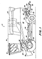
- a harvesting machine 10 shown in FIG. 1 in the form of a Combine is powered on front and rear steerable wheels 12 and 14 worn and has a driver's cabin 16, from which they are operated by a driver can.
- a stationary one could also be used Threshing machine, an experimental threshing system or the like in Question come.
- the driver's cabin 16 closes at the rear a grain tank 18, the material delivered into it via an emptying pipe 20 can deliver to the outside.
- the grain tank 18 is stored on a frame 22, in the supplied material on the way over a threshing drum 24, a threshing basket 26 and a turning drum 28 is broken down into its large and small components.
- a distribution and Comminution device 42 is provided, in which the of the Shakers 30 conveyed components of the crop, such as Straw, due to the action of gravity.
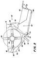
- the distribution and comminution device 42 is shown in FIG. 2 presented in more detail.
- On the drum 48 are Several knives 50 distributed evenly over the circumference arranged movably.
- the material to be conveyed is conveyed by the drum 48 and the knives 50 taken and on a fixed Bar with counter knives 52 passed by.
- the chopped material is conveyed through a narrow gap between the knives 50 and a first area 54 of the Housing 76 of the distribution and comminution device 42 in guided a circular path.
- the housing 76 is on the underside the dropout hood 44 is attached and encloses the drum 48.
- the first region 54 of the housing 76 is thus stationary on the Harvester 10 attached.
- the material to be conveyed is then through the drum 50 to a second area 68 of the housing 76 passed, the first, to the drawing level orthogonal axis 56 is pivotally connected to the housing 76.
- the first area 54 and the second area 68 form one So-called chopper floor, at the end of which the material to be conveyed Leaves circular orbit and ejected backwards to the ground becomes.
- the second area 68 of the housing 76 is a flat one Sheet that extends over the entire effective width of the distribution and Crushing device 42 extends. The bulk of the Conveyed goods leave the circular path at the end of the second area 68 tangential. However, part of the knife 50 and ventilation caused by their rotation torn further. This results in a certain vertical spread in the horizontal direction of ejection.
- the distributor 62 has a horizontal, axis 58 running perpendicular to the plane of the drawing hereinafter referred to as the second axis, pivotable Floor plate 60 on. The slope of the entire manifold 62 relative to the earth can be adjusted in this way.
- a number of baffles 64 is arranged below the Bottom plate 60. The baffles 64 are elongated, perpendicular to Floor plate 60 downwardly extending plates, one after have curvature directed to the right or to the left.
- baffles 64 can be positioned transverse to Driving direction of the harvesting machine 10 can be adjusted. Through the Curvature and orientation become the material to be conveyed Pass the guide plates 64 transverse to the direction of travel Harvester 10 deflected and so over a greater width than that corresponding to the working channel of the harvester 10 spread across the floor.
- the drum 48 works with the knives 50 and the first area 54 and second area 68 of housing 76 as Shredding and conveying device, and the second area 54 and the distributor 62 with the baffles 64 as Distribution device for the conveyed material.
- the chopped material to be conveyed should be as even as possible over the entire cutting width of the harvesting machine 10 can be distributed.
- the even distribution is a prerequisite for that at subsequent operations (tillage or direct sowing without tillage) no clogging of the working machines occur and the soil quality over the entire Width remains the same, i.e. an even storage capacity of moisture and a homogeneous rotting process is achieved.
- the cutting width is much larger than the width of the working channel (the cutting units are up to 9 m wide, and the Channel width is up to about 1.6 m).
- a coupling is used to solve the problem described between the second region 68 of the housing 76 and the the guide plates 64 connected to the distributor 62 are provided.
- levers 74 are attached on the underside.
- the recesses 72 are comb-like in the Introduced underside of the second region 68 and point different distances from the first axis 56.
- the depth of the recesses 72 is also in each case different to the inclination of the baffles 64 and to bring the second region 68 into the desired relation, such as explained below.
- each of these cutouts 72 receives a crossbar 70 which is connected to the distributor 62 connected is.
- the crossbar 70 extends over the total width of the distributor 62, and is over rods 66 and two side plates 78, the (in the direction of travel Harvester 10) left and right edges of the distributor 62 are attached, with the bottom plate 60 and fixed to it Baffles 64 connected.
- the inclination of the distributor 62 is determined.
- the positions are to get adjustment of the ejection direction the first axis 56, the second axis 58 and the recesses 72 selected so that the following criteria are met:
- the imaginary extension of the lower edge of the guide plates 64 should at all positions of the straw distributor 62 Circular motion path, which is guided by the conveyed goods through the first area 54 and second area 68, touch tangentially. In the area where this was intended Extension touches the circular path tangentially the first axis 56. Shortly before that, it ends with the housing 76 firmly connected first area 54.
- the transition from the fixed first area 54 to second area 68 takes place with a small paragraph so that the gap between the two areas 54, 68 lies in the shadow of the movement path of the material being conveyed. Thereby no material can get stuck in the gap.
- the cutouts 72 are connected to the second area 68 so that the second area 68 the material to be conveyed always in the lower area the guide plates 64 aligns. Ideally, the second area 68 directed parallel to the lower edge of the guide plates 64.
- the inclination of the distributor 62 is adjusted as follows: while the manifold 62 is in position is held, the lever 74 turns counterclockwise moves so that the cross bar 70 out of engagement with each recess 72 occupied by her. Then the distributor 62 are pivoted such that the crossbar is close another (desired) recess 72 and the lever 74 can be pivoted clockwise, or simply released be so that it is affected by gravity in Turns clockwise. The locking of the cross bar 70 in the Recess 72 is also made by gravity Generates torque that the distributor 62 clockwise tries to rotate while moving the second area 68 as well turns in that direction.
- the cross bar 70 pressed against the bottom area of the respective recess 72, and second region 68 and manifold 62 are relative to each other, and locked to the first area 54.
- an additional Locking the second area 68 and / or the distributor 62 be appropriate. You can by a (wing) mother on one bolts forming the second axis 58, and / or a removable one Cover (swiveling strip, sheet metal, spring, or the like) be at the bottom of the recesses 72, the one Jump out of the cross bar 70 from the respective recess 72 prevented.
- the additional locking is in front of one Adjustment of the inclination of the distributor 62 to be released and then to get in position again.
- the lever 74 can be tensioned clockwise by a spring, to get a reliable lock. If a feather pulls the lever 74 clockwise, it supports the Gravity, and makes the lever 74 difficult to pull out the recess 72 can pop out. It can be a tension spring below the second area 68 of the housing 76, or a Torsion spring about the first axis 56 can be used.
- the entire manifold 62 counterclockwise from the second area 68 can be pivoted vertically upwards.
- the distributor 62 can be vertically upwards to the Rear wall of the harvester 10 pivoted (and not in the Drawing shown means locked there), so that he e.g. when transporting the harvesting machine 10 in particular does not interfere with the cutting unit carriage attached.
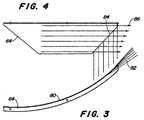
- the guide plates 64 have a curvature 80, which is shown in FIG is reproduced.
- the chopped material to be conveyed is processed accordingly the curvature 80 guided in a curved path.
- At the end of Baffles 64 leave the material being conveyed tangentially to the cam track and is thus opposite to the direction of travel of the harvesting machine 10 thrown sideways onto the field.
- end of the guide plate 64 obliquely at an angle of about 45 ° compared to that indicated by arrows 86 Flow direction of the conveyed material.
- the material to be conveyed in upper area of the guide plate 64 further (i.e. longer) in the Curved path as in the lower.
- the material to be conveyed is the Leaves cam track below earlier than in the upper area, it will not so far laterally distracted. That way it leaves Conveyed material the guide plates 64 without loss of energy in one certain scattering angle 82, and not as a focused beam.
- the effect described is achieved particularly well if that chopped material to be conveyed across the curvature as possible Baffles 64 is guided. That is through the above described solution for adjusting the horizontal ejection direction of straw.
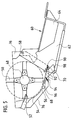
- FIG 5 is a distribution device after a second Embodiment of the invention reproduced. It corresponds to their basic structure that in the previous figures shown first embodiment, however, is the azimuthal Locking the guide plates 64 realized in a different way.
- the housing 76 With the housing 76 is the distributor 62 with the baffles 64 around the axis 58 is pivotally connected.
- the side wall of the Manifold 62 has a circular shape around axis 58 arranged recesses (in the specific bores) 92, through which a bolt 90 can be inserted. The bolt 90 continues to penetrate a hole in a side Outer wall of the housing 76, but for reasons of Clarity is not included.
- Recesses 92 are present so that it can be selected which of them - by pivoting the distributor 62 - with the bore in the side outer wall of the housing 76 in alignment brought.
- the bolt 90 becomes through this recess stuck.
- the pin 90 in the selected Lock opening 92 like split pins.
- the goal and the basic function of the second embodiment also in that the outlet area of the chopper floor and so that the direction of discharge of the chopped material corresponds to the Inclination of the distributor is adjusted so that the chopped material is always optimally guided through the guide plates 64.
- the position of the second region 68 of the housing 76 which like in the first embodiment on its front side around the first Axis 56 is pivotally connected to the housing 76 by arranged at the rear of the second area 68 Slides 98 set on one with the distributor 62nd connected crossbar 70 rest. In this way the Position of the second area 68 by the position of the Distributor 62 determined.
- a spring 94 is connected to the housing 76 and the second area 68 and ensures that the Always slide sliders 98 correctly on crossbar 70.
- a second spring can be on the other side of the Distribution device can be arranged.
- Laterally on the second Area 68 stops 96 do not work with the drawn side wall of the housing 76 together and define a maximum swivel range of the second area 68.
- a limitation of the swivel range is especially at necessary for transport swiveled distributor.
Landscapes
- Life Sciences & Earth Sciences (AREA)
- Environmental Sciences (AREA)
- Threshing Machine Elements (AREA)
- Harvester Elements (AREA)
- Disintegrating Or Milling (AREA)
- Harvesting Machines For Root Crops (AREA)
- Harvesting Machines For Specific Crops (AREA)
Applications Claiming Priority (2)
| Application Number | Priority Date | Filing Date | Title |
|---|---|---|---|
| DE19906454A DE19906454A1 (de) | 1999-02-16 | 1999-02-16 | Verteilvorrichtung einer Zerkleinerungsvorrichtung |
| DE19906454 | 1999-02-16 |
Publications (3)
| Publication Number | Publication Date |
|---|---|
| EP1031272A2 true EP1031272A2 (fr) | 2000-08-30 |
| EP1031272A3 EP1031272A3 (fr) | 2002-03-20 |
| EP1031272B1 EP1031272B1 (fr) | 2006-11-15 |
Family
ID=7897683
Family Applications (1)
| Application Number | Title | Priority Date | Filing Date |
|---|---|---|---|
| EP00101406A Expired - Lifetime EP1031272B1 (fr) | 1999-02-16 | 2000-01-25 | Dispositif de distribution pour broyeur |
Country Status (8)
| Country | Link |
|---|---|
| US (1) | US6331142B1 (fr) |
| EP (1) | EP1031272B1 (fr) |
| AR (1) | AR022576A1 (fr) |
| AT (1) | ATE345032T1 (fr) |
| AU (1) | AU767012B2 (fr) |
| BR (1) | BR0000472A (fr) |
| CA (1) | CA2284125C (fr) |
| DE (2) | DE19906454A1 (fr) |
Cited By (1)
| Publication number | Priority date | Publication date | Assignee | Title |
|---|---|---|---|---|
| EP2848112A1 (fr) * | 2013-09-11 | 2015-03-18 | CLAAS Selbstfahrende Erntemaschinen GmbH | Moissonneuse-batteuse équipée d'un dispositif de séparation |
Families Citing this family (60)
| Publication number | Priority date | Publication date | Assignee | Title |
|---|---|---|---|---|
| DE10063550B4 (de) * | 2000-12-20 | 2008-10-02 | Deere & Company, Moline | Mähdrescher mit Häckseleinrichtung |
| DE10064356A1 (de) | 2000-12-21 | 2002-07-11 | Claas Selbstfahr Erntemasch | Vorrichtung und Verfahren zur Erntegutförderung in landwirtschaftlichen Arbeitsmaschinen |
| DE10207479A1 (de) * | 2002-02-22 | 2003-10-16 | Deere & Co | Verteilvorrichtung für aus einer Erntemaschine austretendes Häckselgut |
| GB0214086D0 (en) * | 2002-06-19 | 2002-07-31 | Cnh Belgium Nv | Crop chopper arrangements for agricultural machinery |
| DE10256744A1 (de) * | 2002-12-05 | 2004-06-17 | Deere & Company, Moline | Mähdrescher mit Strohhäcksler |
| US7306174B2 (en) * | 2004-03-04 | 2007-12-11 | Deere & Company | Broadcast width and location control for a combine spreader |
| CA2465142C (fr) | 2004-04-23 | 2009-06-02 | Redekop Chaff Systems Ltd. | Moissonneuse-batteuse avec dispositif de projection muni d'une commande independante de largeur d'etalement |
| CA2470876C (fr) * | 2004-06-14 | 2009-12-08 | Redekop Chaff Systems Ltd. | Moissonneuse-batteuse a reglage immediat des positions de vidage de paille et de menue paille |
| CA2473341A1 (fr) * | 2004-07-08 | 2006-01-08 | Highline Mfg. Inc. | Faconneuse de balles avec tete de coupe de fourrage |
| US7261633B2 (en) * | 2005-02-15 | 2007-08-28 | Cnh America Llc | Unitary pivoting spreader apparatus |
| US20060246982A1 (en) * | 2005-03-29 | 2006-11-02 | Howard Rubin | Lotto bingo game |
| US7544127B2 (en) * | 2005-06-30 | 2009-06-09 | Deere & Company | Straw chopper for combine with adjustable stationary knife bank |
| US7331855B2 (en) * | 2005-07-15 | 2008-02-19 | Deere & Company | Wide-spread impeller spreader for harvesting combine |
| US7473169B2 (en) * | 2007-02-28 | 2009-01-06 | Cnh America Llc | Adjustable axial rotor discharge deflector |
| US7487024B2 (en) * | 2007-04-26 | 2009-02-03 | Cnh America Llc | Apparatus and method for automatically setting operating parameters for a remotely adjustable spreader of an agricultural harvesting machine |
| US8359988B2 (en) | 2007-07-24 | 2013-01-29 | Dawn Equipment Company | Agricultural tillage device |
| US7485035B1 (en) * | 2007-09-28 | 2009-02-03 | Cnh America Llc | Control system for an adjustable deflector |
| US7635299B2 (en) * | 2007-09-28 | 2009-12-22 | Cnh America Llc | Windrow forming construction |
| US7673570B1 (en) | 2008-12-01 | 2010-03-09 | Dawn Equipment Company | Row-clearing unit for agricultural implement |
| DE102009042002A1 (de) * | 2009-09-21 | 2011-03-24 | Claas Selbstfahrende Erntemaschinen Gmbh | Verfahren und Verteilen eines Gutstromes auf einem Feld sowie Häcksel- und Verteilvorrichtung |
| US8327780B2 (en) | 2009-10-16 | 2012-12-11 | Dawn Equipment Company | Agricultural implement having fluid delivery features |
| US8010262B2 (en) * | 2009-10-21 | 2011-08-30 | Cnh America Llc | Apparatus and method for automatically controlling the settings of an adjustable crop residue spreader of an agricultural combine |
| US9107338B2 (en) | 2010-09-15 | 2015-08-18 | Dawn Equipment Company | Agricultural systems |
| US8763713B2 (en) | 2012-01-27 | 2014-07-01 | Dawn Equipment Company | Agricultural implement with automatic down pressure control |
| US8544397B2 (en) | 2010-09-15 | 2013-10-01 | Dawn Equipment Company | Row unit for agricultural implement |
| US8776702B2 (en) | 2010-09-15 | 2014-07-15 | Dawn Equipment Company | Hydraulic down pressure control system for an agricultural implement |
| US9232687B2 (en) | 2010-09-15 | 2016-01-12 | Dawn Equipment Company | Agricultural systems |
| US8544398B2 (en) | 2010-09-15 | 2013-10-01 | Dawn Equipment Company | Hydraulic down pressure control system for closing wheels of an agricultural implement |
| US9107337B2 (en) | 2012-08-20 | 2015-08-18 | Dawn Equipment Company | Agricultural apparatus for sensing and providing feedback of soil property changes in real time |
| US8985232B2 (en) | 2012-08-20 | 2015-03-24 | Dawn Equipment Company | Agricultural apparatus for sensing and providing feedback of soil property changes in real time |
| US9055712B2 (en) | 2010-09-15 | 2015-06-16 | Dawn Equipment Company | Agricultural apparatus with integrated controller for a row unit |
| US9226440B2 (en) | 2010-09-15 | 2016-01-05 | Dawn Equipment Company | Agricultural apparatus with hydraulic cylinder and manifold for a row unit |
| US8863857B2 (en) | 2011-02-23 | 2014-10-21 | Dawn Equipment Company | Row unit for agricultural implement |
| US9271437B2 (en) | 2011-07-01 | 2016-03-01 | Charles H. Martin | Agricultural field preparation device |
| UA110988C2 (uk) | 2011-08-05 | 2016-03-10 | Пресіжн Плентінг Елелсі | Пристрій, системи і способи регулювання притискної сили рядного висівного апарата |
| US8636077B2 (en) | 2012-05-22 | 2014-01-28 | Dawn Equipment Company | Agricultural tool with structural housing for hydraulic actuator |
| US8910581B2 (en) | 2012-07-25 | 2014-12-16 | Dawn Equipment Company | Side dressing fertilizer coulter |
| ES2927145T3 (es) | 2012-07-25 | 2022-11-02 | Prec Planting Llc | Implemento agrícola con controlador de fuerza descendente |
| US9215839B2 (en) | 2013-02-01 | 2015-12-22 | Dawn Equipment Company | Agricultural apparatus with hybrid single-disk, double-disk coulter arrangement |
| US9192091B2 (en) | 2013-02-01 | 2015-11-24 | Dawn Equipment Company | Agricultural apparatus with hybrid single-disk, double-disk coulter arrangement |
| US10721855B2 (en) | 2014-02-05 | 2020-07-28 | Dawn Equipment Company | Agricultural system for field preparation |
| US9241438B2 (en) | 2014-02-05 | 2016-01-26 | Dawn Equipment Company | Agricultural system for field preparation |
| US9668398B2 (en) | 2014-02-05 | 2017-06-06 | Dawn Equipment Company | Agricultural system for field preparation |
| US9615497B2 (en) | 2014-02-21 | 2017-04-11 | Dawn Equipment Company | Modular autonomous farm vehicle |
| US11197411B2 (en) | 2014-11-07 | 2021-12-14 | Dawn Equipment Company | Agricultural planting system with automatic depth control |
| US9848522B2 (en) | 2014-11-07 | 2017-12-26 | Dawn Equipment Company | Agricultural system |
| US10444774B2 (en) | 2014-11-07 | 2019-10-15 | Dawn Equipment Company | Agricultural system |
| US10582653B2 (en) | 2014-11-07 | 2020-03-10 | Dawn Equipment Company | Agricultural planting system with automatic depth control |
| US9723778B2 (en) | 2014-11-07 | 2017-08-08 | Dawn Equipment Company | Agricultural system |
| US10980174B2 (en) | 2015-12-28 | 2021-04-20 | Underground Agriculture, LLC | Agricultural mowing device |
| US10477760B2 (en) | 2015-12-28 | 2019-11-19 | Underground Agriculture, LLC | Agricultural organic device for weed control |
| US11083134B2 (en) | 2015-12-28 | 2021-08-10 | Underground Agriculture, LLC | Agricultural inter-row mowing device |
| US10645865B2 (en) | 2017-05-04 | 2020-05-12 | Dawn Equipment Company | Agricultural row unit with automatic control system for furrow closing device |
| US11006563B2 (en) | 2017-05-04 | 2021-05-18 | Dawn Equipment Company | Seed firming device for improving seed to soil contact in a planter furrow with feature designed to prevent the buildup of soil on the outer surfaces by discharging pressurized fluid |
| US10548260B2 (en) | 2017-05-04 | 2020-02-04 | Dawn Equipment Company | System for automatically setting the set point of a planter automatic down pressure control system with a seed furrow sidewall compaction measurement device |
| US10822172B1 (en) | 2019-04-29 | 2020-11-03 | Cnh Industrial America Llc | Merger extension chute and conveyor |
| CN110249798A (zh) * | 2019-07-30 | 2019-09-20 | 吉林大学 | 一种秸秆揉丝密化还田机 |
| US20220312675A1 (en) * | 2021-04-06 | 2022-10-06 | Tritana Intellectual Property Ltd. | Combine harvester residue spreader fin shaped to increase spreading action |
| US20230103977A1 (en) * | 2021-10-01 | 2023-04-06 | Cnh Industrial America Llc | Pivotable windrow chute for combine harvester |
| CN114271112B (zh) * | 2021-12-07 | 2023-06-30 | 南京市蓝业科技有限公司 | 一种可以烘干农作物秸秆的固定运输装置 |
Citations (5)
| Publication number | Priority date | Publication date | Assignee | Title |
|---|---|---|---|---|
| US2708582A (en) * | 1952-02-11 | 1955-05-17 | Deere & Co | Straw chopper and spreader attachment for combines |
| FR1239857A (fr) * | 1959-11-06 | 1960-08-26 | Dispositif pour répartir la paille ou autres à la sortie d'appareils de coupe | |
| US3815823A (en) * | 1973-02-27 | 1974-06-11 | Int Harvester Co | Straw chopper attachment for harvester combines |
| DE3438609A1 (de) * | 1984-10-20 | 1986-04-24 | Claas Ohg, 4834 Harsewinkel | Maehdrescher mit anbauhaecksler |
| FR2728759A1 (fr) * | 1994-12-28 | 1996-07-05 | Lucas Sa G | Goulotte d'ejection pour machine agricole de distribution de produits divers |
Family Cites Families (18)
| Publication number | Priority date | Publication date | Assignee | Title |
|---|---|---|---|---|
| DE427376C (de) * | 1922-09-13 | 1926-03-31 | Felix Schlayer Dr | Achsialdreschmaschine |
| US2213906A (en) * | 1939-01-25 | 1940-09-03 | Ebersol Aaron | Straw shredder attachment for threshing machines |
| US3005637A (en) * | 1958-09-08 | 1961-10-24 | Polaris Inc | Straw cutters and spreaders |
| US3186460A (en) * | 1961-07-20 | 1965-06-01 | Frederick Joseph | Straw chopping apparatus |
| US3350017A (en) * | 1965-07-21 | 1967-10-31 | Int Harvester Co | Straw chopper and spreader |
| US3587690A (en) * | 1969-10-20 | 1971-06-28 | Deere & Co | Combine straw chopper mounting |
| US4735216A (en) * | 1982-08-02 | 1988-04-05 | Gehl Company | Straw chopper and spreader assembly |
| DE3415708A1 (de) * | 1984-04-27 | 1985-10-31 | Biso Bitter Gmbh & Co Kg, 4520 Melle | Maehdrescher |
| US4637406A (en) * | 1984-08-09 | 1987-01-20 | Hesston Corporation | Chaff and straw spreading attachment for combines |
| DE3530195C1 (de) * | 1985-08-23 | 1987-03-05 | Biso Bitter Gmbh & Co Kg | Verteilereinrichtung fuer Haecksler |
| US4669489A (en) * | 1985-12-02 | 1987-06-02 | Deere & Company | Straw chopper mounting for a combine |
| SE8603089D0 (sv) * | 1986-07-11 | 1986-07-11 | Rekordverken Ab | Anordning vid med slaghack forsedda skordetroskor |
| DE3834102A1 (de) * | 1988-10-07 | 1990-04-12 | Claas Ohg | Maehdrescher |
| US5120275A (en) * | 1990-08-09 | 1992-06-09 | Rem Manufacturing Limited | Chaff spreading attachment for combines |
| DE4341764C1 (de) * | 1993-12-08 | 1995-01-19 | Claas Ohg | Mähdrescher mit Strohhäcksler |
| DE4419421C2 (de) * | 1994-06-03 | 1996-03-28 | Claas Ohg | Verteilvorrichtung für Häcksler |
| US5542883A (en) * | 1995-06-02 | 1996-08-06 | Dutch Industries Ltd. | Straw spreading system |
| SE504681C2 (sv) * | 1995-09-06 | 1997-04-07 | Rekordverken Ab | Skärmaskin vid skördetröska med en fläkt för extra luft |
-
1999
- 1999-02-16 DE DE19906454A patent/DE19906454A1/de not_active Ceased
- 1999-09-22 US US09/401,553 patent/US6331142B1/en not_active Expired - Lifetime
- 1999-09-28 CA CA002284125A patent/CA2284125C/fr not_active Expired - Fee Related
-
2000
- 2000-01-21 AU AU13495/00A patent/AU767012B2/en not_active Ceased
- 2000-01-25 DE DE50013727T patent/DE50013727D1/de not_active Expired - Lifetime
- 2000-01-25 EP EP00101406A patent/EP1031272B1/fr not_active Expired - Lifetime
- 2000-01-25 AT AT00101406T patent/ATE345032T1/de active
- 2000-02-11 AR ARP000100603A patent/AR022576A1/es active IP Right Grant
- 2000-02-15 BR BR0000472-3A patent/BR0000472A/pt not_active IP Right Cessation
Patent Citations (5)
| Publication number | Priority date | Publication date | Assignee | Title |
|---|---|---|---|---|
| US2708582A (en) * | 1952-02-11 | 1955-05-17 | Deere & Co | Straw chopper and spreader attachment for combines |
| FR1239857A (fr) * | 1959-11-06 | 1960-08-26 | Dispositif pour répartir la paille ou autres à la sortie d'appareils de coupe | |
| US3815823A (en) * | 1973-02-27 | 1974-06-11 | Int Harvester Co | Straw chopper attachment for harvester combines |
| DE3438609A1 (de) * | 1984-10-20 | 1986-04-24 | Claas Ohg, 4834 Harsewinkel | Maehdrescher mit anbauhaecksler |
| FR2728759A1 (fr) * | 1994-12-28 | 1996-07-05 | Lucas Sa G | Goulotte d'ejection pour machine agricole de distribution de produits divers |
Cited By (2)
| Publication number | Priority date | Publication date | Assignee | Title |
|---|---|---|---|---|
| EP2848112A1 (fr) * | 2013-09-11 | 2015-03-18 | CLAAS Selbstfahrende Erntemaschinen GmbH | Moissonneuse-batteuse équipée d'un dispositif de séparation |
| EP2848112B1 (fr) | 2013-09-11 | 2016-06-08 | CLAAS Selbstfahrende Erntemaschinen GmbH | Moissonneuse-batteuse équipée d'un dispositif de séparation |
Also Published As
| Publication number | Publication date |
|---|---|
| DE50013727D1 (de) | 2006-12-28 |
| US6331142B1 (en) | 2001-12-18 |
| ATE345032T1 (de) | 2006-12-15 |
| DE19906454A1 (de) | 2000-08-31 |
| EP1031272A3 (fr) | 2002-03-20 |
| AU767012B2 (en) | 2003-10-30 |
| CA2284125C (fr) | 2004-11-23 |
| AR022576A1 (es) | 2002-09-04 |
| EP1031272B1 (fr) | 2006-11-15 |
| CA2284125A1 (fr) | 2000-08-16 |
| BR0000472A (pt) | 2000-11-14 |
| AU1349500A (en) | 2000-08-17 |
Similar Documents
| Publication | Publication Date | Title |
|---|---|---|
| EP1031272B1 (fr) | Dispositif de distribution pour broyeur | |
| EP1163834B1 (fr) | Dispositif à répartir pour hacheur | |
| EP1074176B1 (fr) | Hache-paille | |
| EP0580026B1 (fr) | Faucheuse avec boîtier et avec canal arrière d'expectoration ayant un dispositif de guidage | |
| EP0856244B1 (fr) | Tondeuse de paillage | |
| EP2298061B1 (fr) | Procédé de répartition d'un flux de matière sur un champ et dispositif de hachage et de répartition | |
| EP1232683A1 (fr) | Eléments entraíneurs ef dispositif broyeur pour machine agricole | |
| DE2729033A1 (de) | Maehdrescher | |
| EP1111985A1 (fr) | Dispositif permettant de moissonner des produits agricoles de type paille | |
| DE2118914A1 (de) | Aus wenigstens einem Paar zusammenwirkender Mähkreisel bestehendes Mähwerk und nachgeschaltetem Quetschwalzenpaar bestehende Halmgutaufbereitungsmaschine | |
| DE2425372A1 (de) | Feldhaecksler | |
| EP2232976B1 (fr) | Agencement de hachage et de répartition de résidus de produits de récolte pour une moissonneuse-batteuse | |
| DE102013211829B4 (de) | Element zum Abstützen und/oder Leiten von Erntegut in einer Erntemaschine | |
| DE2636488C2 (fr) | ||
| EP1849348A1 (fr) | Dispositif de broyage secondaire doté de lames de coupes secondaires amovibles | |
| DE4313841A1 (de) | Mähdrescher | |
| EP0862849B1 (fr) | Dispositif pour le traitement de récolte | |
| DE19916645A1 (de) | Fördererzusammenbau | |
| EP1031271B1 (fr) | Dispositif de distribution pour broyeur | |
| DE6931693U (de) | Feldhaecksler | |
| DE1942733A1 (de) | Erntemaschine | |
| EP1078566B1 (fr) | Déflecteur pour un distributeur de paille | |
| EP2181578A2 (fr) | Moissonneuse-batteuse et procédé de récolte | |
| DE4105017C2 (fr) | ||
| DE102005048052A1 (de) | Erntegutresteverteileinrichtung für einen Mähdrescher |
Legal Events
| Date | Code | Title | Description |
|---|---|---|---|
| PUAI | Public reference made under article 153(3) epc to a published international application that has entered the european phase |
Free format text: ORIGINAL CODE: 0009012 |
|
| AK | Designated contracting states |
Kind code of ref document: A2 Designated state(s): AT BE CH CY DE DK ES FI FR GB GR IE IT LI LU MC NL PT SE |
|
| AX | Request for extension of the european patent |
Free format text: AL;LT;LV;MK;RO;SI |
|
| PUAL | Search report despatched |
Free format text: ORIGINAL CODE: 0009013 |
|
| AK | Designated contracting states |
Kind code of ref document: A3 Designated state(s): AT BE CH CY DE DK ES FI FR GB GR IE IT LI LU MC NL PT SE |
|
| AX | Request for extension of the european patent |
Free format text: AL;LT;LV;MK;RO;SI |
|
| 17P | Request for examination filed |
Effective date: 20020920 |
|
| AKX | Designation fees paid |
Free format text: AT BE CH CY DE DK ES FI FR GB GR IE IT LI LU MC NL PT SE |
|
| GRAP | Despatch of communication of intention to grant a patent |
Free format text: ORIGINAL CODE: EPIDOSNIGR1 |
|
| GRAS | Grant fee paid |
Free format text: ORIGINAL CODE: EPIDOSNIGR3 |
|
| GRAA | (expected) grant |
Free format text: ORIGINAL CODE: 0009210 |
|
| AK | Designated contracting states |
Kind code of ref document: B1 Designated state(s): AT BE CH CY DE DK ES FI FR GB GR IE IT LI LU MC NL PT SE |
|
| PG25 | Lapsed in a contracting state [announced via postgrant information from national office to epo] |
Ref country code: IT Free format text: LAPSE BECAUSE OF FAILURE TO SUBMIT A TRANSLATION OF THE DESCRIPTION OR TO PAY THE FEE WITHIN THE PRESCRIBED TIME-LIMIT;WARNING: LAPSES OF ITALIAN PATENTS WITH EFFECTIVE DATE BEFORE 2007 MAY HAVE OCCURRED AT ANY TIME BEFORE 2007. THE CORRECT EFFECTIVE DATE MAY BE DIFFERENT FROM THE ONE RECORDED. Effective date: 20061115 Ref country code: FI Free format text: LAPSE BECAUSE OF FAILURE TO SUBMIT A TRANSLATION OF THE DESCRIPTION OR TO PAY THE FEE WITHIN THE PRESCRIBED TIME-LIMIT Effective date: 20061115 Ref country code: IE Free format text: LAPSE BECAUSE OF FAILURE TO SUBMIT A TRANSLATION OF THE DESCRIPTION OR TO PAY THE FEE WITHIN THE PRESCRIBED TIME-LIMIT Effective date: 20061115 Ref country code: NL Free format text: LAPSE BECAUSE OF FAILURE TO SUBMIT A TRANSLATION OF THE DESCRIPTION OR TO PAY THE FEE WITHIN THE PRESCRIBED TIME-LIMIT Effective date: 20061115 |
|
| REG | Reference to a national code |
Ref country code: GB Ref legal event code: FG4D Free format text: NOT ENGLISH |
|
| REG | Reference to a national code |
Ref country code: CH Ref legal event code: EP |
|
| REF | Corresponds to: |
Ref document number: 50013727 Country of ref document: DE Date of ref document: 20061228 Kind code of ref document: P |
|
| REG | Reference to a national code |
Ref country code: IE Ref legal event code: FG4D Free format text: LANGUAGE OF EP DOCUMENT: GERMAN |
|
| PG25 | Lapsed in a contracting state [announced via postgrant information from national office to epo] |
Ref country code: LI Free format text: LAPSE BECAUSE OF NON-PAYMENT OF DUE FEES Effective date: 20070131 Ref country code: MC Free format text: LAPSE BECAUSE OF NON-PAYMENT OF DUE FEES Effective date: 20070131 Ref country code: CH Free format text: LAPSE BECAUSE OF NON-PAYMENT OF DUE FEES Effective date: 20070131 |
|
| REG | Reference to a national code |
Ref country code: SE Ref legal event code: TRGR |
|
| PG25 | Lapsed in a contracting state [announced via postgrant information from national office to epo] |
Ref country code: DK Free format text: LAPSE BECAUSE OF FAILURE TO SUBMIT A TRANSLATION OF THE DESCRIPTION OR TO PAY THE FEE WITHIN THE PRESCRIBED TIME-LIMIT Effective date: 20070215 |
|
| PG25 | Lapsed in a contracting state [announced via postgrant information from national office to epo] |
Ref country code: ES Free format text: LAPSE BECAUSE OF FAILURE TO SUBMIT A TRANSLATION OF THE DESCRIPTION OR TO PAY THE FEE WITHIN THE PRESCRIBED TIME-LIMIT Effective date: 20070226 |
|
| PG25 | Lapsed in a contracting state [announced via postgrant information from national office to epo] |
Ref country code: PT Free format text: LAPSE BECAUSE OF FAILURE TO SUBMIT A TRANSLATION OF THE DESCRIPTION OR TO PAY THE FEE WITHIN THE PRESCRIBED TIME-LIMIT Effective date: 20070416 |
|
| NLV1 | Nl: lapsed or annulled due to failure to fulfill the requirements of art. 29p and 29m of the patents act | ||
| GBV | Gb: ep patent (uk) treated as always having been void in accordance with gb section 77(7)/1977 [no translation filed] |
Effective date: 20061115 |
|
| REG | Reference to a national code |
Ref country code: IE Ref legal event code: FD4D |
|
| EN | Fr: translation not filed | ||
| EN | Fr: translation not filed | ||
| REG | Reference to a national code |
Ref country code: CH Ref legal event code: PL |
|
| PLBE | No opposition filed within time limit |
Free format text: ORIGINAL CODE: 0009261 |
|
| STAA | Information on the status of an ep patent application or granted ep patent |
Free format text: STATUS: NO OPPOSITION FILED WITHIN TIME LIMIT |
|
| 26N | No opposition filed |
Effective date: 20070817 |
|
| PG25 | Lapsed in a contracting state [announced via postgrant information from national office to epo] |
Ref country code: GB Free format text: LAPSE BECAUSE OF FAILURE TO SUBMIT A TRANSLATION OF THE DESCRIPTION OR TO PAY THE FEE WITHIN THE PRESCRIBED TIME-LIMIT Effective date: 20061115 |
|
| PG25 | Lapsed in a contracting state [announced via postgrant information from national office to epo] |
Ref country code: FR Free format text: LAPSE BECAUSE OF FAILURE TO SUBMIT A TRANSLATION OF THE DESCRIPTION OR TO PAY THE FEE WITHIN THE PRESCRIBED TIME-LIMIT Effective date: 20070629 Ref country code: GR Free format text: LAPSE BECAUSE OF FAILURE TO SUBMIT A TRANSLATION OF THE DESCRIPTION OR TO PAY THE FEE WITHIN THE PRESCRIBED TIME-LIMIT Effective date: 20070216 |
|
| PG25 | Lapsed in a contracting state [announced via postgrant information from national office to epo] |
Ref country code: FR Free format text: LAPSE BECAUSE OF FAILURE TO SUBMIT A TRANSLATION OF THE DESCRIPTION OR TO PAY THE FEE WITHIN THE PRESCRIBED TIME-LIMIT Effective date: 20061115 |
|
| PG25 | Lapsed in a contracting state [announced via postgrant information from national office to epo] |
Ref country code: LU Free format text: LAPSE BECAUSE OF NON-PAYMENT OF DUE FEES Effective date: 20070125 Ref country code: CY Free format text: LAPSE BECAUSE OF FAILURE TO SUBMIT A TRANSLATION OF THE DESCRIPTION OR TO PAY THE FEE WITHIN THE PRESCRIBED TIME-LIMIT Effective date: 20061115 |
|
| PGFP | Annual fee paid to national office [announced via postgrant information from national office to epo] |
Ref country code: AT Payment date: 20160104 Year of fee payment: 17 |
|
| REG | Reference to a national code |
Ref country code: AT Ref legal event code: MM01 Ref document number: 345032 Country of ref document: AT Kind code of ref document: T Effective date: 20170125 |
|
| PG25 | Lapsed in a contracting state [announced via postgrant information from national office to epo] |
Ref country code: AT Free format text: LAPSE BECAUSE OF NON-PAYMENT OF DUE FEES Effective date: 20170125 |
|
| PGFP | Annual fee paid to national office [announced via postgrant information from national office to epo] |
Ref country code: DE Payment date: 20181219 Year of fee payment: 20 |
|
| PGFP | Annual fee paid to national office [announced via postgrant information from national office to epo] |
Ref country code: BE Payment date: 20190128 Year of fee payment: 20 Ref country code: SE Payment date: 20190129 Year of fee payment: 20 |
|
| REG | Reference to a national code |
Ref country code: DE Ref legal event code: R071 Ref document number: 50013727 Country of ref document: DE |
|
| REG | Reference to a national code |
Ref country code: SE Ref legal event code: EUG |
|
| REG | Reference to a national code |
Ref country code: BE Ref legal event code: MK Effective date: 20200125 |