EP1031272B1 - Dispositif de distribution pour broyeur - Google Patents
Dispositif de distribution pour broyeur Download PDFInfo
- Publication number
- EP1031272B1 EP1031272B1 EP00101406A EP00101406A EP1031272B1 EP 1031272 B1 EP1031272 B1 EP 1031272B1 EP 00101406 A EP00101406 A EP 00101406A EP 00101406 A EP00101406 A EP 00101406A EP 1031272 B1 EP1031272 B1 EP 1031272B1
- Authority
- EP
- European Patent Office
- Prior art keywords
- housing
- region
- guide vanes
- axis
- baffles
- Prior art date
- Legal status (The legal status is an assumption and is not a legal conclusion. Google has not performed a legal analysis and makes no representation as to the accuracy of the status listed.)
- Expired - Lifetime
Links
Images
Classifications
-
- A—HUMAN NECESSITIES
- A01—AGRICULTURE; FORESTRY; ANIMAL HUSBANDRY; HUNTING; TRAPPING; FISHING
- A01F—PROCESSING OF HARVESTED PRODUCE; HAY OR STRAW PRESSES; DEVICES FOR STORING AGRICULTURAL OR HORTICULTURAL PRODUCE
- A01F12/00—Parts or details of threshing apparatus
- A01F12/40—Arrangements of straw crushers or cutters
-
- Y—GENERAL TAGGING OF NEW TECHNOLOGICAL DEVELOPMENTS; GENERAL TAGGING OF CROSS-SECTIONAL TECHNOLOGIES SPANNING OVER SEVERAL SECTIONS OF THE IPC; TECHNICAL SUBJECTS COVERED BY FORMER USPC CROSS-REFERENCE ART COLLECTIONS [XRACs] AND DIGESTS
- Y10—TECHNICAL SUBJECTS COVERED BY FORMER USPC
- Y10S—TECHNICAL SUBJECTS COVERED BY FORMER USPC CROSS-REFERENCE ART COLLECTIONS [XRACs] AND DIGESTS
- Y10S460/00—Crop threshing or separating
- Y10S460/901—Material distributor
Definitions
- the invention relates to a distribution device of a crushing device, comprising a housing having a first region and second region, a crushing and conveying element arranged in the housing and a plurality of baffles for transversely scattering the conveyed material, which are in a certain spatial relationship to the second region of the housing wherein the second region of the housing is pivotable about a first axis relative to the first region of the housing, and conveyed material is conveyed by the conveying element past the first and second regions toward the baffles, and wherein the baffles are relative to the first region of the housing , Separate from the second region of the housing, are pivotable about a second axis which is parallel to the first axis and the baffles are connected by their pivotal mounting directly or indirectly to the first region of the housing or the second region of the housing.
- a combine harvester on which a mounted chopper is arranged, which is provided with a rotatively driven cutter shaft with knives attached thereto, and a housing enclosing them.
- the chopped straw exits through an ejection housing, in which several baffles are attached.
- the ejection housing is pivotally mounted around the cutter shaft.
- the exit area of the chopper shaft is defined by the bottom of the ejection housing, which is azimuthally pivotable together with the ejection housing around the chopper shaft. In this way, the discharge ratios should remain constant at all pivot positions of the ejection housing.
- the object of the invention is to provide an improved distribution device of a comminution device.
- the baffles separately from the second region of the housing, pivotally mounted.
- the conveyed material is passed through a gap between the crushing and conveying element and the first and second region of the housing of the distributor during operation of the distributor and then ejected. It reaches the baffles which serve to convey the material as evenly as possible in the lateral direction, i. transversal to the funding direction, to distribute.
- the second region of the housing is pivotally mounted so as to be able to position it in such a way that the conveyed material is guided as long as possible and thrown onto the guide plates in a targeted manner.
- the airflow generated by the impeller is then also optimally in the desired direction, i. on the baffles, out, and supports the ejection of the conveyed material.
- the second portion of the housing prevents unintentional engagement in the crushing and conveying element.
- the second region of the housing extends, as preferably also the first region of the housing, as a rule over the entire width of the comminuting and conveying element.
- the straw distributor can be fixed in working position in different inclinations. The aim is to influence by the second area, the horizontal direction of ejection from the chopper so that the chopped straw is optimally directed at each inclination of the distributor by the baffles.
- the baffles are pivotally arranged according to the invention that they are in a certain spatial relationship to the second region of the housing. Normally, the straw distributor is faced with the baffles in its inclination adjusted to the horizontal, in order to influence the spread. The second area of the housing then adapts to the slope of the straw distributor. This ensures that the baffles are optimally hit by the conveyed.
- the baffles usually consist of a plurality of vertically arranged sheets whose longitudinal axis extends in the direction of transport of the conveyed material. The sheets usually have a curvature in the horizontal direction, and can be designed adjustable or bendable in its lateral position.
- the baffles are pivotable about a second axis which is parallel to the first axis and spaced therefrom.
- the second axis may connect the baffles to the second portion of the housing, or alternatively make an indirect or immediate connection between the baffles and the first part of the housing.
- the guide plates could be pivoted into an inoperative position in the direction of the first region of the housing, whereas in the second case they could be pivoted in the opposite direction away from the second region of the housing.
- the advantages of the invention are, in particular, that in a compact structure and good ejection of the conveyed the baffles are pivoted separately, and therefore can be swiveled up or down for road transport. There is thus no unfavorable rigid, bulky ejection housing, and no displacement of the distribution device in the operating and inoperative position longer necessary.
- the invention can be applied to vertically and horizontally oriented first and second axes.
- the conveyor element which is also usually driven in rotation, preferably rotates about an axis which is also parallel to the first and second axes.
- the invention is thus applicable to conveyor elements with horizontally oriented axes of rotation, as well as conveyor elements with vertically oriented axes of rotation.
- the first edge of the baffles seen in the vertical direction lower edge. Since different ejection directions are desirable, said geometric condition is preferably achieved in a plurality of detent positions between the second region of the housing and the baffles.
- first latching element which is set up to receive a complementary second latching element connected to the baffles or the second region.
- second region or the housing, or the baffles
- the locking elements are preferably provided at the lateral edge of the first or second region, but could also be attached to the center or at another point, in particular when the distribution device is divided into two laterally juxtaposed devices.
- a chain may be used which is connected at one end to the baffles (or the second region) and whose links are selectively hookable to the second region (or baffles).
- hooks or cams of different lengths can be used, or locked in different positions.
- a rod which engages in one or more corresponding recesses or bears against sliding elements.
- the first latching elements contain recesses which have different distances from the first and second axes.
- the positions of the recesses are chosen so that the desired azimuthal angles of the second region and the baffles are achieved.
- the second region be essentially straight, ie provided with a flat, non-curved, effective surface.
- a curved, in about the outer circle of the conveying element adapted second region would be conceivable.
- the crushing and conveying element may be a cutter shaft with knives attached thereto which interact with counter knives.
- At least one of the baffles is curved and the conveying element facing away from the end of this baffle is bevelled with respect to the flow direction of the conveyed.
- a striking the baffle particle of the conveyed is deflected by an angle which depends on the position (height perpendicular to the transport direction of the conveyed material) and flight direction (angle of impact of the particle) of the particle upon impact with the baffle since the respective particle is deflected by the bevel at an angle dependent on these parameters and leaves the baffle sooner or later.
- the conveyed leaves the baffles therefore in a scattering angle range. It can be configured such a part of the baffles, or all baffles.
- the invention finds particular use in harvesters such as combine harvesters.
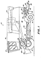
- a harvester 10 in the form of a combine harvester shown in Figure 1 is supported on front driven and rear steerable wheels 12 and 14, respectively, and has a driver's cab 16 from which it can be operated by a driver.
- a driver's cab 16 from which it can be operated by a driver.
- a stationary threshing machine, a trial threshing system or the like could also be considered.
- a grain tank 18 connects at the rear, which can deliver good discharged into it via an emptying tube 20 to the outside.
- the grain tank 18 rests on a frame 22, in the supplied good on the way via a threshing drum 24, a concave 26 and a beater 28 is decomposed into its large and small components.
- a distribution and crushing device 42 into which the crop ingredients conveyed by the shakers 30, e.g. Straw, due to the action of gravity arrive.
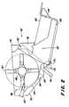
- the distribution and crushing device 42 is shown in more detail in FIG.
- the conveyed material is taken by the drum 48 and the knives 50 and pulled past a fixed bar with counter knives 52. By the knife 50 and the counter knife 52, the material is chopped into short sections.
- the drum 48 with the blades 50 acts as a crushing and conveying element in the result.
- shredders in which instead of the movable blades 50 on the drum 48 only fixed drive plates are arranged. These drive plates guide the straw through fixed counter blades. The teaching of the invention is also applicable to these designs.
- the chopped conveyed material is guided through a narrow gap between the blades 50 and a first region 54 of the housing 76 of the distribution and crushing device 42 in a circular path.
- the housing 76 is attached to the underside of the failure hood 44, and encloses the drum 48.
- the first portion 54 of the housing 76 is thus fixedly attached to the harvester 10.
- the conveyed material is then guided by the drum 50 past a second region 68 of the housing 76, which is pivotably connected to the housing 76 on a first axis orthogonal to the plane of the drawing.
- the first region 54 and the second region 68 form a so-called chopper bottom, at the end of the conveyed leaves the circular path and is ejected backwards to the ground.
- the second region 68 of the housing 76 is a flat sheet which extends over the entire effective width of the distribution and crushing device 42. The majority of the conveyed material leaves the circular path at the end of the second region 68 tangentially. However, a part is torn further by the knives 50 and the ventilation resulting from their rotation. This results in a certain vertical dispersion in the horizontal direction of ejection.
- a so-called distributor 62 is arranged at the rear end of the crushing and distributing device 42. Through him, the chopped conveyed as evenly distributed to the cutting width of the harvester 10 transverse to the direction of travel.
- the distributor 62 has a pivotable bottom plate 60 about a horizontal axis 58, which is perpendicular to the plane of the drawing and is referred to below as the second axis. The inclination of the entire distributor 62 relative to the ground can thus be adjusted.
- a number of baffles 64 is arranged below the bottom plate 60. The baffles 64 are elongate, perpendicular to the bottom plate 60 downwardly extending sheets having a right or left curvature.
- the baffles 64 may be adjusted in position transverse to the direction of travel of the harvester 10. Due to the curvature and the orientation of the conveyed material is deflected when passing the baffles 64 transversely to the direction of travel of the harvester 10 and thus distributed over a greater width than that corresponding to the working channel of the harvester 10, distributed on the ground.
- the drum 48 acts with the blades 50 and the first portion 54 and second portion 68 of the housing 76 as a crushing and conveying device, and the second portion 54 and the manifold 62 with the baffles 64 as a distributor for the conveyed material.
- the chopped conveyed should be distributed as evenly as possible over the entire cutting width of the harvester 10.
- the uniform distribution is a prerequisite that in subsequent operations (tillage or direct sowing without tillage) no clogging of the machines occur and the soil quality remains the same over the entire width, i. a uniform storage capacity of moisture and a homogeneous rotting process is achieved.
- the cutting width is much greater than the width of the working channel (the cutting units are up to 9 m wide, and the channel width is up to about 1.6 m).
- the distribution of very moist or green and heavy conveyed material is critical, since the air resistance can not swirl the conveyed material as much as dry conveyed material, which is braked after leaving the guide vanes 64 by the air resistance and somewhat swirled, and thus as a uniform layer on the ground to come to rest.
- the moist or green conveyed leaves the baffles 64 in an undesirable manner radially and is bundled so thrown to the ground. This results in clearly visible strips behind the harvester 10, which can be assigned to the individual baffles 64.
- a coupling between the second portion 68 of the housing 76 and the guide plates 64 connected to the distributor 62 is provided.
- lever 74 are mounted on the underside.
- recesses 72 are provided on the underside of the second area 68 (in the forward direction of travel of the harvester 10) behind the levers 74.
- the recesses 72 are inserted into the underside of the second area 68 in a comb-like manner and each have different distances from the first axis 56.
- the depth of the recesses 72 is also different in each case in order to bring the inclination of the guide plates 64 and the second area 68 into the desired relation, as explained below.
- one of these recesses 72 receives a crossbar 70 which is connected to the distributor 62.
- the cross bar 70 extends across the entire width of the distributor 62, and is connected to the bottom plate 60 and the fixed thereon by means of bars 66 and two side plates 78 which are mounted on the left and right edges of the distributor 62 (in the direction of travel of the harvester 10) Guiding plates 64 connected.
- the inclination of the distributor 62 is determined.
- the inclination of the second portion 68 of the housing 76 and thus the horizontal direction of ejection of the chopped conveyed is adapted to the distribution slope.
- the positions of the first axis 56, the second axis 58 and the recesses 72 are selected such that the following criteria are met:
- the imaginary extension of the lower edge of the guide plates 64 For all positions of the straw distributor 62, the movement circle path resulting from the guidance of the conveyed material through the first area 54 and the second area 68 should touch tangentially. In the area where this imaginary extension tangentially touches the circular path, there is the first axis 56. Just before it ends with the housing 76th firmly connected first region 54.
- the transition from the fixed first region 54 to the second region 68 is carried out with a small shoulder so that the gap between the two areas 54, 68 is in the shadow of the movement path of the conveyed material. As a result, no conveyed material can settle in the gap.
- the recesses 72 are connected to the second region 68 such that the second region 68 always directs the conveyed material into the lower region of the guide plates 64. Ideally, the second region 68 is directed parallel to the lower edge of the baffles 64.
- the adjustment of the inclination of the distributor 62 is as follows: while the distributor 62 is held in position, the lever 74 is moved in the counterclockwise direction, so that the crossbar 70 is disengaged from the respectively occupied by her recess 72. Then, the distributor 62 can be pivoted so that the crossbar comes close to another (desired) recess 72, and the lever 74 can be pivoted clockwise, or simply let go, so that it rotates by the action of gravity in a clockwise direction.
- the locking of the crossbar 70 in the recess 72 is also by gravity, which generates a torque that attempts to rotate the distributor 62 in a clockwise direction, while also rotating the second region 68 in that direction.
- the crossbar 70 is pressed against the bottom portion of the respective recess 72, and the second portion 68 and the manifold 62 are relative to each other and locked to the first portion 54.
- an additional locking of the second region 68 and / or the distributor 62 may be expedient. It can by a (wing) nut on a bolt forming the second axis 58, and / or a removable cover (hinged bar, sheet metal, spring, or the like) be on the underside of the recesses 72, which prevents jumping out of the crossbar 70 from the respective recess 72.
- the additional lock is to be released before an adjustment of the inclination of the distributor 62 and then bring back into position.
- the lever 74 can be tensioned by a spring in a clockwise direction to obtain a reliable locking. When a spring pulls the lever 74 in a clockwise direction, it supports gravity, and ensures that the lever 74 is difficult to jump out of the recess 72.
- a tension spring below the second portion 68 of the housing 76 or a torsion spring about the first axis 56 may be used.
- the entire manifold 62 can be pivoted counterclockwise from the second region 68 vertically upward.
- the distributor 62 can be pivoted vertically upwards to the rear wall of the harvester 10 (and locked there by means not shown in the drawing), e.g. when road transport of the harvester 10, in particular with attached cutting carriage does not bother.
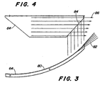
- the baffles 64 have a curvature 80, which is shown in FIG.
- the chopped conveyed is guided according to the curvature 80 in a curved path.
- the conveyed leaves the curved path tangentially and is thus deflected laterally deflected relative to the direction of travel of the harvester 10 onto the field.
- the recognizable in Figure 4 end of the guide plate 64 extends obliquely at an angle of approximately 45 ° relative to the direction indicated by arrows 86 flow direction of the conveyed.
- the conveyed Since the conveyed leaves the curved path earlier than in the upper area, it is not deflected so far laterally. In this way, the conveyed leaves the baffles 64 without loss of energy in a certain scattering angle 82, and not as a focused beam.
- the described effect is achieved particularly well when the chopped conveyed as possible transverse to the curvature is guided by the baffles 64. This is achieved by the above-described solution for adjusting the horizontal direction of ejection of the straw.
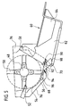
- FIG. 5 shows a distribution device according to a second embodiment of the invention. It corresponds in its basic structure of the first embodiment shown in the preceding figures, however, the azimuthal locking of the baffles 64 is realized in other ways.
- the side wall of the distributor 62 has circularly arranged around the axis 58 around recesses (in the concrete holes) 92, through which a bolt 90 can be plugged.
- the bolt 90 also penetrates a hole in a lateral outer wall of the housing 76, which is not drawn in for reasons of clarity.
- the position of the second portion 68 of the housing 76 which is pivotally connected to the housing 76 at its front about the first axis 56 as in the first embodiment, is defined by arranged on the rear side of the second portion 68 sliders 98, which on one with the distributor 62 connected crossbar 70 rest. In this way, the position of the second region 68 is determined by the position of the distributor 62.
- a spring 94 is connected to the housing 76 and the second region 68 and ensures that the sliders 98 always rest correctly on the crossbar 70.
- a second spring may be disposed on the other side of the distributor. Stops 96 arranged laterally on the second region 68 cooperate with the side wall of the housing 76 (not shown) and define a maximum pivoting range of the second region 68.
- a limitation of the pivoting range is necessary, in particular for distributors pivoted upwards for transport. Another possibility of limiting the pivoting range consists in tongues on the sliders or the outlet area, which engage in corresponding recesses in the side walls.
Claims (9)
- Dispositif de distribution d'un dispositif de hachage, comportant un carter (76), qui est muni d'une première partie (54) et d'une deuxième partie (68), un élément de hachage et de transport, agencé dans le carter (76), et plusieurs plaques de guidage (64) pour répandre transversalement le produit transporté, lesquelles sont disposées selon une position dans l'espace déterminée par rapport à la deuxième partie (68) du carter (76), la deuxième partie (68) du carter (76) étant apte à pivoter autour d'un premier axe (56) par rapport à la première partie (54) du carter (76) et le produit récolté étant transporté par l'élément de transport le long de la première (54) et de la deuxième partie (68) vers les plaques de guidage (64), et les plaques de guidage (64) étant aptes à pivoter par rapport à la première partie (54) du carter (76), séparément de la deuxième partie (68) du carter (76), autour d'un deuxième axe (58), qui est parallèle au premier axe (56), et les plaques de guidage (64) étant reliées par leur palier de pivotement directement ou indirectement avec la première partie (54) du carter (76) ou la deuxième partie (68) du carter (76), caractérisé en ce que le carter (76) ou la deuxième partie (68) du carter (76) et les plaques de guidage (64) peuvent être assemblés les uns aux autres par complémentarité de forme, en particulier par encliquetage.
- Dispositif de distribution selon la revendication 1, caractérisé en ce que le carter (76) ou la deuxième partie (68) du carter (76) et les plaques de guidage (64) peuvent être encliquetés les uns dans les autres de telle sorte que, dans plusieurs positions de fixation, un prolongement imaginaire d'un premier bord, de préférence le bord inférieur des plaques de guidage (64), est au moins à peu près tangent à la trajectoire de mouvement du produit transporté, qui est obtenue par l'élément de transport en coopération avec la deuxième partie (68) du carter (76).
- Dispositif de distribution selon l'une quelconque des revendications 1 à 2, caractérisé en ce que, de préférence sur le bord latéral de la deuxième partie (68) ou du carter (76), est ou sont agencé(s) un premier élément de fixation ou plusieurs éléments de fixation qui est ou sont réalisé(s) pour coopérer avec un deuxième élément de fixation complémentaire, en particulier une tige (70) ou un évidement (92), lequel est relié aux plaques de guidage (64).
- Dispositif de distribution selon la revendication 3, caractérisé en ce que les premiers éléments de fixation contiennent des évidements (72, 92), qui sont situés en particulier à différentes distances du premier axe (56) et du deuxième axe (58).
- Dispositif de distribution selon l'une quelconque des revendications 1 à 4, caractérisé en ce que la deuxième partie (68) est sensiblement droite et le deuxième axe (58) et les éléments de fixation sont positionnés de telle sorte qu'un prolongement imaginaire d'un premier bord des plaques de guidage (64) coupe le premier axe (56).
- Dispositif de distribution selon l'une quelconque des revendications précédentes, caractérisé en ce que la deuxième partie (68), par exemple par l'intermédiaire d'éléments de glissement (98) et/ou d'une tige (70) s'engageant dans des évidements (72), est couplée avec les plaques de guidage (64) de telle sorte que sa position dépend de la position des plaques de guidage (64).
- Dispositif de distribution selon l'une quelconque des revendications précédentes, caractérisé en ce que l'élément de hachage et de transport comporte un tambour (48) avec des couteaux (50) fixés contre celui-ci, lesquels coopèrent de préférence avec des contre-couteaux (52).
- Dispositif de distribution selon l'une quelconque des revendications précédentes, caractérisé en ce qu'au moins l'une des plaques de guidage (64) est courbe et l'extrémité, opposée à l'élément de transport, de cette plaque de guidage (64) est chanfreinée par rapport à la direction du flux du produit transporté.
- Combinaison formée par une machine de récolte (10), en particulier une moissonneuse-batteuse, et un dispositif de distribution selon l'une quelconque des revendications précédentes.
Applications Claiming Priority (2)
| Application Number | Priority Date | Filing Date | Title |
|---|---|---|---|
| DE19906454A DE19906454A1 (de) | 1999-02-16 | 1999-02-16 | Verteilvorrichtung einer Zerkleinerungsvorrichtung |
| DE19906454 | 1999-02-16 |
Publications (3)
| Publication Number | Publication Date |
|---|---|
| EP1031272A2 EP1031272A2 (fr) | 2000-08-30 |
| EP1031272A3 EP1031272A3 (fr) | 2002-03-20 |
| EP1031272B1 true EP1031272B1 (fr) | 2006-11-15 |
Family
ID=7897683
Family Applications (1)
| Application Number | Title | Priority Date | Filing Date |
|---|---|---|---|
| EP00101406A Expired - Lifetime EP1031272B1 (fr) | 1999-02-16 | 2000-01-25 | Dispositif de distribution pour broyeur |
Country Status (8)
| Country | Link |
|---|---|
| US (1) | US6331142B1 (fr) |
| EP (1) | EP1031272B1 (fr) |
| AR (1) | AR022576A1 (fr) |
| AT (1) | ATE345032T1 (fr) |
| AU (1) | AU767012B2 (fr) |
| BR (1) | BR0000472A (fr) |
| CA (1) | CA2284125C (fr) |
| DE (2) | DE19906454A1 (fr) |
Families Citing this family (61)
| Publication number | Priority date | Publication date | Assignee | Title |
|---|---|---|---|---|
| DE10063550B4 (de) * | 2000-12-20 | 2008-10-02 | Deere & Company, Moline | Mähdrescher mit Häckseleinrichtung |
| DE10064356A1 (de) | 2000-12-21 | 2002-07-11 | Claas Selbstfahr Erntemasch | Vorrichtung und Verfahren zur Erntegutförderung in landwirtschaftlichen Arbeitsmaschinen |
| DE10207479A1 (de) * | 2002-02-22 | 2003-10-16 | Deere & Co | Verteilvorrichtung für aus einer Erntemaschine austretendes Häckselgut |
| GB0214086D0 (en) * | 2002-06-19 | 2002-07-31 | Cnh Belgium Nv | Crop chopper arrangements for agricultural machinery |
| DE10256744A1 (de) * | 2002-12-05 | 2004-06-17 | Deere & Company, Moline | Mähdrescher mit Strohhäcksler |
| US7306174B2 (en) * | 2004-03-04 | 2007-12-11 | Deere & Company | Broadcast width and location control for a combine spreader |
| CA2465142C (fr) | 2004-04-23 | 2009-06-02 | Redekop Chaff Systems Ltd. | Moissonneuse-batteuse avec dispositif de projection muni d'une commande independante de largeur d'etalement |
| CA2470876C (fr) * | 2004-06-14 | 2009-12-08 | Redekop Chaff Systems Ltd. | Moissonneuse-batteuse a reglage immediat des positions de vidage de paille et de menue paille |
| CA2473341A1 (fr) * | 2004-07-08 | 2006-01-08 | Highline Mfg. Inc. | Faconneuse de balles avec tete de coupe de fourrage |
| US7261633B2 (en) * | 2005-02-15 | 2007-08-28 | Cnh America Llc | Unitary pivoting spreader apparatus |
| US20060246982A1 (en) * | 2005-03-29 | 2006-11-02 | Howard Rubin | Lotto bingo game |
| US7544127B2 (en) * | 2005-06-30 | 2009-06-09 | Deere & Company | Straw chopper for combine with adjustable stationary knife bank |
| US7331855B2 (en) * | 2005-07-15 | 2008-02-19 | Deere & Company | Wide-spread impeller spreader for harvesting combine |
| US7473169B2 (en) * | 2007-02-28 | 2009-01-06 | Cnh America Llc | Adjustable axial rotor discharge deflector |
| US7487024B2 (en) * | 2007-04-26 | 2009-02-03 | Cnh America Llc | Apparatus and method for automatically setting operating parameters for a remotely adjustable spreader of an agricultural harvesting machine |
| US8359988B2 (en) | 2007-07-24 | 2013-01-29 | Dawn Equipment Company | Agricultural tillage device |
| US7485035B1 (en) * | 2007-09-28 | 2009-02-03 | Cnh America Llc | Control system for an adjustable deflector |
| US7635299B2 (en) * | 2007-09-28 | 2009-12-22 | Cnh America Llc | Windrow forming construction |
| US7673570B1 (en) | 2008-12-01 | 2010-03-09 | Dawn Equipment Company | Row-clearing unit for agricultural implement |
| DE102009042002A1 (de) * | 2009-09-21 | 2011-03-24 | Claas Selbstfahrende Erntemaschinen Gmbh | Verfahren und Verteilen eines Gutstromes auf einem Feld sowie Häcksel- und Verteilvorrichtung |
| US8327780B2 (en) | 2009-10-16 | 2012-12-11 | Dawn Equipment Company | Agricultural implement having fluid delivery features |
| US8010262B2 (en) * | 2009-10-21 | 2011-08-30 | Cnh America Llc | Apparatus and method for automatically controlling the settings of an adjustable crop residue spreader of an agricultural combine |
| US9107338B2 (en) | 2010-09-15 | 2015-08-18 | Dawn Equipment Company | Agricultural systems |
| US8763713B2 (en) | 2012-01-27 | 2014-07-01 | Dawn Equipment Company | Agricultural implement with automatic down pressure control |
| US8544397B2 (en) | 2010-09-15 | 2013-10-01 | Dawn Equipment Company | Row unit for agricultural implement |
| US8776702B2 (en) | 2010-09-15 | 2014-07-15 | Dawn Equipment Company | Hydraulic down pressure control system for an agricultural implement |
| US9232687B2 (en) | 2010-09-15 | 2016-01-12 | Dawn Equipment Company | Agricultural systems |
| US8544398B2 (en) | 2010-09-15 | 2013-10-01 | Dawn Equipment Company | Hydraulic down pressure control system for closing wheels of an agricultural implement |
| US9107337B2 (en) | 2012-08-20 | 2015-08-18 | Dawn Equipment Company | Agricultural apparatus for sensing and providing feedback of soil property changes in real time |
| US8985232B2 (en) | 2012-08-20 | 2015-03-24 | Dawn Equipment Company | Agricultural apparatus for sensing and providing feedback of soil property changes in real time |
| US9055712B2 (en) | 2010-09-15 | 2015-06-16 | Dawn Equipment Company | Agricultural apparatus with integrated controller for a row unit |
| US9226440B2 (en) | 2010-09-15 | 2016-01-05 | Dawn Equipment Company | Agricultural apparatus with hydraulic cylinder and manifold for a row unit |
| US8863857B2 (en) | 2011-02-23 | 2014-10-21 | Dawn Equipment Company | Row unit for agricultural implement |
| US9271437B2 (en) | 2011-07-01 | 2016-03-01 | Charles H. Martin | Agricultural field preparation device |
| UA110988C2 (uk) | 2011-08-05 | 2016-03-10 | Пресіжн Плентінг Елелсі | Пристрій, системи і способи регулювання притискної сили рядного висівного апарата |
| US8636077B2 (en) | 2012-05-22 | 2014-01-28 | Dawn Equipment Company | Agricultural tool with structural housing for hydraulic actuator |
| US8910581B2 (en) | 2012-07-25 | 2014-12-16 | Dawn Equipment Company | Side dressing fertilizer coulter |
| ES2927145T3 (es) | 2012-07-25 | 2022-11-02 | Prec Planting Llc | Implemento agrícola con controlador de fuerza descendente |
| US9215839B2 (en) | 2013-02-01 | 2015-12-22 | Dawn Equipment Company | Agricultural apparatus with hybrid single-disk, double-disk coulter arrangement |
| US9192091B2 (en) | 2013-02-01 | 2015-11-24 | Dawn Equipment Company | Agricultural apparatus with hybrid single-disk, double-disk coulter arrangement |
| DE102013109983A1 (de) * | 2013-09-11 | 2015-03-12 | Claas Selbstfahrende Erntemaschinen Gmbh | Mähdrescher mit einer Abscheidevorrichtung |
| US10721855B2 (en) | 2014-02-05 | 2020-07-28 | Dawn Equipment Company | Agricultural system for field preparation |
| US9241438B2 (en) | 2014-02-05 | 2016-01-26 | Dawn Equipment Company | Agricultural system for field preparation |
| US9668398B2 (en) | 2014-02-05 | 2017-06-06 | Dawn Equipment Company | Agricultural system for field preparation |
| US9615497B2 (en) | 2014-02-21 | 2017-04-11 | Dawn Equipment Company | Modular autonomous farm vehicle |
| US11197411B2 (en) | 2014-11-07 | 2021-12-14 | Dawn Equipment Company | Agricultural planting system with automatic depth control |
| US9848522B2 (en) | 2014-11-07 | 2017-12-26 | Dawn Equipment Company | Agricultural system |
| US10444774B2 (en) | 2014-11-07 | 2019-10-15 | Dawn Equipment Company | Agricultural system |
| US10582653B2 (en) | 2014-11-07 | 2020-03-10 | Dawn Equipment Company | Agricultural planting system with automatic depth control |
| US9723778B2 (en) | 2014-11-07 | 2017-08-08 | Dawn Equipment Company | Agricultural system |
| US10980174B2 (en) | 2015-12-28 | 2021-04-20 | Underground Agriculture, LLC | Agricultural mowing device |
| US10477760B2 (en) | 2015-12-28 | 2019-11-19 | Underground Agriculture, LLC | Agricultural organic device for weed control |
| US11083134B2 (en) | 2015-12-28 | 2021-08-10 | Underground Agriculture, LLC | Agricultural inter-row mowing device |
| US10645865B2 (en) | 2017-05-04 | 2020-05-12 | Dawn Equipment Company | Agricultural row unit with automatic control system for furrow closing device |
| US11006563B2 (en) | 2017-05-04 | 2021-05-18 | Dawn Equipment Company | Seed firming device for improving seed to soil contact in a planter furrow with feature designed to prevent the buildup of soil on the outer surfaces by discharging pressurized fluid |
| US10548260B2 (en) | 2017-05-04 | 2020-02-04 | Dawn Equipment Company | System for automatically setting the set point of a planter automatic down pressure control system with a seed furrow sidewall compaction measurement device |
| US10822172B1 (en) | 2019-04-29 | 2020-11-03 | Cnh Industrial America Llc | Merger extension chute and conveyor |
| CN110249798A (zh) * | 2019-07-30 | 2019-09-20 | 吉林大学 | 一种秸秆揉丝密化还田机 |
| US20220312675A1 (en) * | 2021-04-06 | 2022-10-06 | Tritana Intellectual Property Ltd. | Combine harvester residue spreader fin shaped to increase spreading action |
| US20230103977A1 (en) * | 2021-10-01 | 2023-04-06 | Cnh Industrial America Llc | Pivotable windrow chute for combine harvester |
| CN114271112B (zh) * | 2021-12-07 | 2023-06-30 | 南京市蓝业科技有限公司 | 一种可以烘干农作物秸秆的固定运输装置 |
Family Cites Families (23)
| Publication number | Priority date | Publication date | Assignee | Title |
|---|---|---|---|---|
| DE427376C (de) * | 1922-09-13 | 1926-03-31 | Felix Schlayer Dr | Achsialdreschmaschine |
| US2213906A (en) * | 1939-01-25 | 1940-09-03 | Ebersol Aaron | Straw shredder attachment for threshing machines |
| US2708582A (en) * | 1952-02-11 | 1955-05-17 | Deere & Co | Straw chopper and spreader attachment for combines |
| US3005637A (en) * | 1958-09-08 | 1961-10-24 | Polaris Inc | Straw cutters and spreaders |
| FR1239857A (fr) * | 1959-11-06 | 1960-08-26 | Dispositif pour répartir la paille ou autres à la sortie d'appareils de coupe | |
| US3186460A (en) * | 1961-07-20 | 1965-06-01 | Frederick Joseph | Straw chopping apparatus |
| US3350017A (en) * | 1965-07-21 | 1967-10-31 | Int Harvester Co | Straw chopper and spreader |
| US3587690A (en) * | 1969-10-20 | 1971-06-28 | Deere & Co | Combine straw chopper mounting |
| US3815823A (en) * | 1973-02-27 | 1974-06-11 | Int Harvester Co | Straw chopper attachment for harvester combines |
| US4735216A (en) * | 1982-08-02 | 1988-04-05 | Gehl Company | Straw chopper and spreader assembly |
| DE3415708A1 (de) * | 1984-04-27 | 1985-10-31 | Biso Bitter Gmbh & Co Kg, 4520 Melle | Maehdrescher |
| US4637406A (en) * | 1984-08-09 | 1987-01-20 | Hesston Corporation | Chaff and straw spreading attachment for combines |
| DE3438609A1 (de) * | 1984-10-20 | 1986-04-24 | Claas Ohg, 4834 Harsewinkel | Maehdrescher mit anbauhaecksler |
| DE3530195C1 (de) * | 1985-08-23 | 1987-03-05 | Biso Bitter Gmbh & Co Kg | Verteilereinrichtung fuer Haecksler |
| US4669489A (en) * | 1985-12-02 | 1987-06-02 | Deere & Company | Straw chopper mounting for a combine |
| SE8603089D0 (sv) * | 1986-07-11 | 1986-07-11 | Rekordverken Ab | Anordning vid med slaghack forsedda skordetroskor |
| DE3834102A1 (de) * | 1988-10-07 | 1990-04-12 | Claas Ohg | Maehdrescher |
| US5120275A (en) * | 1990-08-09 | 1992-06-09 | Rem Manufacturing Limited | Chaff spreading attachment for combines |
| DE4341764C1 (de) * | 1993-12-08 | 1995-01-19 | Claas Ohg | Mähdrescher mit Strohhäcksler |
| DE4419421C2 (de) * | 1994-06-03 | 1996-03-28 | Claas Ohg | Verteilvorrichtung für Häcksler |
| FR2728759B1 (fr) * | 1994-12-28 | 1997-03-21 | Lucas Sa G | Goulotte d'ejection pour machine agricole de distribution de produits divers |
| US5542883A (en) * | 1995-06-02 | 1996-08-06 | Dutch Industries Ltd. | Straw spreading system |
| SE504681C2 (sv) * | 1995-09-06 | 1997-04-07 | Rekordverken Ab | Skärmaskin vid skördetröska med en fläkt för extra luft |
-
1999
- 1999-02-16 DE DE19906454A patent/DE19906454A1/de not_active Ceased
- 1999-09-22 US US09/401,553 patent/US6331142B1/en not_active Expired - Lifetime
- 1999-09-28 CA CA002284125A patent/CA2284125C/fr not_active Expired - Fee Related
-
2000
- 2000-01-21 AU AU13495/00A patent/AU767012B2/en not_active Ceased
- 2000-01-25 DE DE50013727T patent/DE50013727D1/de not_active Expired - Lifetime
- 2000-01-25 EP EP00101406A patent/EP1031272B1/fr not_active Expired - Lifetime
- 2000-01-25 AT AT00101406T patent/ATE345032T1/de active
- 2000-02-11 AR ARP000100603A patent/AR022576A1/es active IP Right Grant
- 2000-02-15 BR BR0000472-3A patent/BR0000472A/pt not_active IP Right Cessation
Also Published As
| Publication number | Publication date |
|---|---|
| DE50013727D1 (de) | 2006-12-28 |
| US6331142B1 (en) | 2001-12-18 |
| ATE345032T1 (de) | 2006-12-15 |
| DE19906454A1 (de) | 2000-08-31 |
| EP1031272A3 (fr) | 2002-03-20 |
| AU767012B2 (en) | 2003-10-30 |
| CA2284125C (fr) | 2004-11-23 |
| AR022576A1 (es) | 2002-09-04 |
| CA2284125A1 (fr) | 2000-08-16 |
| EP1031272A2 (fr) | 2000-08-30 |
| BR0000472A (pt) | 2000-11-14 |
| AU1349500A (en) | 2000-08-17 |
Similar Documents
| Publication | Publication Date | Title |
|---|---|---|
| EP1031272B1 (fr) | Dispositif de distribution pour broyeur | |
| EP1163834B2 (fr) | Dispositif à répartir pour hacheur | |
| EP2298061B1 (fr) | Procédé de répartition d'un flux de matière sur un champ et dispositif de hachage et de répartition | |
| EP1074176B1 (fr) | Hache-paille | |
| EP0580026B1 (fr) | Faucheuse avec boîtier et avec canal arrière d'expectoration ayant un dispositif de guidage | |
| EP1074175B1 (fr) | Distributeur pour le résidu des produits de récolte éjecté d'une moissonneuse-batteuse | |
| EP1219164B1 (fr) | Procédé et dispositif pour convoyer des récoltes dans une machine agricole | |
| DE602004000245T2 (de) | Ablenkungsplatte für einen Mähdrescherhäcksler | |
| EP0958727B1 (fr) | Dispositif d'épandage de balle pour moissonneuse-batteuse | |
| EP2175710A1 (fr) | Moissonneuse-batteuse avec un transporteur à tambour supplémentaire pour l'évacuation de la paille et un seul clapet pour l'alternance entre le déversement des andains et le hachage de la paille | |
| EP1232683A1 (fr) | Eléments entraíneurs ef dispositif broyeur pour machine agricole | |
| DE2118914A1 (de) | Aus wenigstens einem Paar zusammenwirkender Mähkreisel bestehendes Mähwerk und nachgeschaltetem Quetschwalzenpaar bestehende Halmgutaufbereitungsmaschine | |
| EP2232976B1 (fr) | Agencement de hachage et de répartition de résidus de produits de récolte pour une moissonneuse-batteuse | |
| DE3319138A1 (de) | -axial-dresch- und trennanordnung fuer maehdrescher mit einer vorrichtung zum zerkleinern des strohs und zum ausbreiten des zerkleinerten strohs auf dem boden | |
| DE2636488C2 (fr) | ||
| EP1849348B1 (fr) | Dispositif de broyage secondaire doté de lames de coupes secondaires amovibles | |
| EP3520596A1 (fr) | Moissonneuse-batteuse | |
| DE4313841A1 (de) | Mähdrescher | |
| EP1031271B1 (fr) | Dispositif de distribution pour broyeur | |
| DE6931693U (de) | Feldhaecksler | |
| EP0498294B1 (fr) | Tondeuse avec caisse de tondeuse à fond ouvert | |
| DE1071403B (fr) | ||
| DE4406304C2 (de) | Häckseleinrichtung zur Zerkleinerung von Erntegut | |
| EP0568961A2 (fr) | Hâcheuse de balles | |
| DE1942733A1 (de) | Erntemaschine |
Legal Events
| Date | Code | Title | Description |
|---|---|---|---|
| PUAI | Public reference made under article 153(3) epc to a published international application that has entered the european phase |
Free format text: ORIGINAL CODE: 0009012 |
|
| AK | Designated contracting states |
Kind code of ref document: A2 Designated state(s): AT BE CH CY DE DK ES FI FR GB GR IE IT LI LU MC NL PT SE |
|
| AX | Request for extension of the european patent |
Free format text: AL;LT;LV;MK;RO;SI |
|
| PUAL | Search report despatched |
Free format text: ORIGINAL CODE: 0009013 |
|
| AK | Designated contracting states |
Kind code of ref document: A3 Designated state(s): AT BE CH CY DE DK ES FI FR GB GR IE IT LI LU MC NL PT SE |
|
| AX | Request for extension of the european patent |
Free format text: AL;LT;LV;MK;RO;SI |
|
| 17P | Request for examination filed |
Effective date: 20020920 |
|
| AKX | Designation fees paid |
Free format text: AT BE CH CY DE DK ES FI FR GB GR IE IT LI LU MC NL PT SE |
|
| GRAP | Despatch of communication of intention to grant a patent |
Free format text: ORIGINAL CODE: EPIDOSNIGR1 |
|
| GRAS | Grant fee paid |
Free format text: ORIGINAL CODE: EPIDOSNIGR3 |
|
| GRAA | (expected) grant |
Free format text: ORIGINAL CODE: 0009210 |
|
| AK | Designated contracting states |
Kind code of ref document: B1 Designated state(s): AT BE CH CY DE DK ES FI FR GB GR IE IT LI LU MC NL PT SE |
|
| PG25 | Lapsed in a contracting state [announced via postgrant information from national office to epo] |
Ref country code: IT Free format text: LAPSE BECAUSE OF FAILURE TO SUBMIT A TRANSLATION OF THE DESCRIPTION OR TO PAY THE FEE WITHIN THE PRESCRIBED TIME-LIMIT;WARNING: LAPSES OF ITALIAN PATENTS WITH EFFECTIVE DATE BEFORE 2007 MAY HAVE OCCURRED AT ANY TIME BEFORE 2007. THE CORRECT EFFECTIVE DATE MAY BE DIFFERENT FROM THE ONE RECORDED. Effective date: 20061115 Ref country code: FI Free format text: LAPSE BECAUSE OF FAILURE TO SUBMIT A TRANSLATION OF THE DESCRIPTION OR TO PAY THE FEE WITHIN THE PRESCRIBED TIME-LIMIT Effective date: 20061115 Ref country code: IE Free format text: LAPSE BECAUSE OF FAILURE TO SUBMIT A TRANSLATION OF THE DESCRIPTION OR TO PAY THE FEE WITHIN THE PRESCRIBED TIME-LIMIT Effective date: 20061115 Ref country code: NL Free format text: LAPSE BECAUSE OF FAILURE TO SUBMIT A TRANSLATION OF THE DESCRIPTION OR TO PAY THE FEE WITHIN THE PRESCRIBED TIME-LIMIT Effective date: 20061115 |
|
| REG | Reference to a national code |
Ref country code: GB Ref legal event code: FG4D Free format text: NOT ENGLISH |
|
| REG | Reference to a national code |
Ref country code: CH Ref legal event code: EP |
|
| REF | Corresponds to: |
Ref document number: 50013727 Country of ref document: DE Date of ref document: 20061228 Kind code of ref document: P |
|
| REG | Reference to a national code |
Ref country code: IE Ref legal event code: FG4D Free format text: LANGUAGE OF EP DOCUMENT: GERMAN |
|
| PG25 | Lapsed in a contracting state [announced via postgrant information from national office to epo] |
Ref country code: LI Free format text: LAPSE BECAUSE OF NON-PAYMENT OF DUE FEES Effective date: 20070131 Ref country code: MC Free format text: LAPSE BECAUSE OF NON-PAYMENT OF DUE FEES Effective date: 20070131 Ref country code: CH Free format text: LAPSE BECAUSE OF NON-PAYMENT OF DUE FEES Effective date: 20070131 |
|
| REG | Reference to a national code |
Ref country code: SE Ref legal event code: TRGR |
|
| PG25 | Lapsed in a contracting state [announced via postgrant information from national office to epo] |
Ref country code: DK Free format text: LAPSE BECAUSE OF FAILURE TO SUBMIT A TRANSLATION OF THE DESCRIPTION OR TO PAY THE FEE WITHIN THE PRESCRIBED TIME-LIMIT Effective date: 20070215 |
|
| PG25 | Lapsed in a contracting state [announced via postgrant information from national office to epo] |
Ref country code: ES Free format text: LAPSE BECAUSE OF FAILURE TO SUBMIT A TRANSLATION OF THE DESCRIPTION OR TO PAY THE FEE WITHIN THE PRESCRIBED TIME-LIMIT Effective date: 20070226 |
|
| PG25 | Lapsed in a contracting state [announced via postgrant information from national office to epo] |
Ref country code: PT Free format text: LAPSE BECAUSE OF FAILURE TO SUBMIT A TRANSLATION OF THE DESCRIPTION OR TO PAY THE FEE WITHIN THE PRESCRIBED TIME-LIMIT Effective date: 20070416 |
|
| NLV1 | Nl: lapsed or annulled due to failure to fulfill the requirements of art. 29p and 29m of the patents act | ||
| GBV | Gb: ep patent (uk) treated as always having been void in accordance with gb section 77(7)/1977 [no translation filed] |
Effective date: 20061115 |
|
| REG | Reference to a national code |
Ref country code: IE Ref legal event code: FD4D |
|
| EN | Fr: translation not filed | ||
| EN | Fr: translation not filed | ||
| REG | Reference to a national code |
Ref country code: CH Ref legal event code: PL |
|
| PLBE | No opposition filed within time limit |
Free format text: ORIGINAL CODE: 0009261 |
|
| STAA | Information on the status of an ep patent application or granted ep patent |
Free format text: STATUS: NO OPPOSITION FILED WITHIN TIME LIMIT |
|
| 26N | No opposition filed |
Effective date: 20070817 |
|
| PG25 | Lapsed in a contracting state [announced via postgrant information from national office to epo] |
Ref country code: GB Free format text: LAPSE BECAUSE OF FAILURE TO SUBMIT A TRANSLATION OF THE DESCRIPTION OR TO PAY THE FEE WITHIN THE PRESCRIBED TIME-LIMIT Effective date: 20061115 |
|
| PG25 | Lapsed in a contracting state [announced via postgrant information from national office to epo] |
Ref country code: FR Free format text: LAPSE BECAUSE OF FAILURE TO SUBMIT A TRANSLATION OF THE DESCRIPTION OR TO PAY THE FEE WITHIN THE PRESCRIBED TIME-LIMIT Effective date: 20070629 Ref country code: GR Free format text: LAPSE BECAUSE OF FAILURE TO SUBMIT A TRANSLATION OF THE DESCRIPTION OR TO PAY THE FEE WITHIN THE PRESCRIBED TIME-LIMIT Effective date: 20070216 |
|
| PG25 | Lapsed in a contracting state [announced via postgrant information from national office to epo] |
Ref country code: FR Free format text: LAPSE BECAUSE OF FAILURE TO SUBMIT A TRANSLATION OF THE DESCRIPTION OR TO PAY THE FEE WITHIN THE PRESCRIBED TIME-LIMIT Effective date: 20061115 |
|
| PG25 | Lapsed in a contracting state [announced via postgrant information from national office to epo] |
Ref country code: LU Free format text: LAPSE BECAUSE OF NON-PAYMENT OF DUE FEES Effective date: 20070125 Ref country code: CY Free format text: LAPSE BECAUSE OF FAILURE TO SUBMIT A TRANSLATION OF THE DESCRIPTION OR TO PAY THE FEE WITHIN THE PRESCRIBED TIME-LIMIT Effective date: 20061115 |
|
| PGFP | Annual fee paid to national office [announced via postgrant information from national office to epo] |
Ref country code: AT Payment date: 20160104 Year of fee payment: 17 |
|
| REG | Reference to a national code |
Ref country code: AT Ref legal event code: MM01 Ref document number: 345032 Country of ref document: AT Kind code of ref document: T Effective date: 20170125 |
|
| PG25 | Lapsed in a contracting state [announced via postgrant information from national office to epo] |
Ref country code: AT Free format text: LAPSE BECAUSE OF NON-PAYMENT OF DUE FEES Effective date: 20170125 |
|
| PGFP | Annual fee paid to national office [announced via postgrant information from national office to epo] |
Ref country code: DE Payment date: 20181219 Year of fee payment: 20 |
|
| PGFP | Annual fee paid to national office [announced via postgrant information from national office to epo] |
Ref country code: BE Payment date: 20190128 Year of fee payment: 20 Ref country code: SE Payment date: 20190129 Year of fee payment: 20 |
|
| REG | Reference to a national code |
Ref country code: DE Ref legal event code: R071 Ref document number: 50013727 Country of ref document: DE |
|
| REG | Reference to a national code |
Ref country code: SE Ref legal event code: EUG |
|
| REG | Reference to a national code |
Ref country code: BE Ref legal event code: MK Effective date: 20200125 |