EP1030938B1 - Garnverwirbelungsvorrichtung und verfahren zum verwirbeln von multifilamentgarnen - Google Patents
Garnverwirbelungsvorrichtung und verfahren zum verwirbeln von multifilamentgarnen Download PDFInfo
- Publication number
- EP1030938B1 EP1030938B1 EP98961002A EP98961002A EP1030938B1 EP 1030938 B1 EP1030938 B1 EP 1030938B1 EP 98961002 A EP98961002 A EP 98961002A EP 98961002 A EP98961002 A EP 98961002A EP 1030938 B1 EP1030938 B1 EP 1030938B1
- Authority
- EP
- European Patent Office
- Prior art keywords
- section
- stream
- yarn
- interlacing device
- main
- Prior art date
- Legal status (The legal status is an assumption and is not a legal conclusion. Google has not performed a legal analysis and makes no representation as to the accuracy of the status listed.)
- Expired - Lifetime
Links
- 238000000034 method Methods 0.000 title claims description 14
- 238000007664 blowing Methods 0.000 description 28
- 238000011144 upstream manufacturing Methods 0.000 description 9
- 230000000694 effects Effects 0.000 description 8
- 238000004519 manufacturing process Methods 0.000 description 4
- 230000003993 interaction Effects 0.000 description 3
- 238000009940 knitting Methods 0.000 description 3
- 239000004753 textile Substances 0.000 description 3
- 230000007547 defect Effects 0.000 description 2
- 239000004744 fabric Substances 0.000 description 2
- 239000000835 fiber Substances 0.000 description 2
- -1 polypropylene Polymers 0.000 description 2
- 229920001169 thermoplastic Polymers 0.000 description 2
- 239000004416 thermosoftening plastic Substances 0.000 description 2
- 238000009732 tufting Methods 0.000 description 2
- OKTJSMMVPCPJKN-UHFFFAOYSA-N Carbon Chemical compound [C] OKTJSMMVPCPJKN-UHFFFAOYSA-N 0.000 description 1
- 229920000271 Kevlar® Polymers 0.000 description 1
- 239000004952 Polyamide Substances 0.000 description 1
- 239000004698 Polyethylene Substances 0.000 description 1
- 239000004743 Polypropylene Substances 0.000 description 1
- 229920000297 Rayon Polymers 0.000 description 1
- 241001620634 Roger Species 0.000 description 1
- 229920002334 Spandex Polymers 0.000 description 1
- 229910052799 carbon Inorganic materials 0.000 description 1
- 238000005520 cutting process Methods 0.000 description 1
- 239000011521 glass Substances 0.000 description 1
- 238000010409 ironing Methods 0.000 description 1
- 239000004761 kevlar Substances 0.000 description 1
- 239000000463 material Substances 0.000 description 1
- 239000000203 mixture Substances 0.000 description 1
- 230000003287 optical effect Effects 0.000 description 1
- 230000000149 penetrating effect Effects 0.000 description 1
- 230000002093 peripheral effect Effects 0.000 description 1
- 229920002647 polyamide Polymers 0.000 description 1
- 229920000728 polyester Polymers 0.000 description 1
- 229920000573 polyethylene Polymers 0.000 description 1
- 229920001155 polypropylene Polymers 0.000 description 1
- 230000001681 protective effect Effects 0.000 description 1
- 238000000926 separation method Methods 0.000 description 1
- 238000009958 sewing Methods 0.000 description 1
- 239000007787 solid Substances 0.000 description 1
- 238000009987 spinning Methods 0.000 description 1
- 238000009941 weaving Methods 0.000 description 1
- 238000004804 winding Methods 0.000 description 1
Images


Classifications
-
- D—TEXTILES; PAPER
- D02—YARNS; MECHANICAL FINISHING OF YARNS OR ROPES; WARPING OR BEAMING
- D02J—FINISHING OR DRESSING OF FILAMENTS, YARNS, THREADS, CORDS, ROPES OR THE LIKE
- D02J1/00—Modifying the structure or properties resulting from a particular structure; Modifying, retaining, or restoring the physical form or cross-sectional shape, e.g. by use of dies or squeeze rollers
- D02J1/08—Interlacing constituent filaments without breakage thereof, e.g. by use of turbulent air streams
-
- D—TEXTILES; PAPER
- D02—YARNS; MECHANICAL FINISHING OF YARNS OR ROPES; WARPING OR BEAMING
- D02G—CRIMPING OR CURLING FIBRES, FILAMENTS, THREADS, OR YARNS; YARNS OR THREADS
- D02G1/00—Producing crimped or curled fibres, filaments, yarns, or threads, giving them latent characteristics
- D02G1/16—Producing crimped or curled fibres, filaments, yarns, or threads, giving them latent characteristics using jets or streams of turbulent gases, e.g. air, steam
- D02G1/161—Producing crimped or curled fibres, filaments, yarns, or threads, giving them latent characteristics using jets or streams of turbulent gases, e.g. air, steam yarn crimping air jets
Definitions
- the invention relates to a swirling device for swirling of multifilament yarns according to the preamble of the claim 1 and a method of swirling at least a multifilament yarn according to the preamble of claim 18.
- Swirling devices and methods of those mentioned here kind are known from DE 37 11 759 C2. They serve the cohesion of the filaments of the multifilament yarn and to improve its further workability since that single multifilament yarn when it is the interlacing device is fed, is still unrotated or only slight Protective twist, which still does not have sufficient cohesion preferably thermoplastic or other materials existing filaments for further processing.
- the multifilament yarn receives the necessary cohesion only by swirling its filaments.
- the swirling device can also use the filaments of multiple multifilament yarns swirled together to form a multifilament yarn become.
- the swirl quality / swirl result is characterized by intermingling points, i.e. the confusion / entanglements of the filaments, and the one between the Interlacing points in which there are essentially non-swirled, i.e. open yarn places.
- intermingling points i.e. the confusion / entanglements of the filaments
- Interlacing points in which there are essentially non-swirled, i.e. open yarn places.
- Such yarns show only a small thread closure and can be used without additional measures associated with high costs, for example Twisting / twisting or finishing, not or only to a limited extent to be processed further.
- Thiread closure is a common term for the compactness of the multifilament yarn and describes the cohesion or cohesion of the Filaments.
- the known interlacing device has a yarn channel through which the multifilament yarn having a number of filaments to be led.
- the filaments are by means of one emerging from an opening cross section of a blowing nozzle Compressed air flow swirled.
- the blow nozzle has usual a circular or elliptical opening cross-section on, which is formed symmetrically to the longitudinal central axis of the yarn channel is.
- the swirling device has the disadvantage on that not in all cases the intermingling of the filaments of the multifilament yarn to a desired interlacing result leads.
- the multifilament yarn shows irregularities, in some cases longer missing parts, that is, non-vortexed ones Yarn places, what in the processing of the multifilament yarn, for example weaving, tufting, knitting, knitting, Sewing will result in these open, unprotected threads to be damaged. Break individual filaments and push themselves up, causing a thread break or the break of Neighboring threads and / or defects in textile fabrics arise.
- CH-PS 415 939 it is known to the media supply lines a circular cross section or any other suitable To give shape, such as rectangle, oval shape or the like.
- the present invention relates to a nozzle channel mouth, whose shape depends on the fact that the medium, especially compressed air, in the form of a main stream in the middle Area and pairwise side streams in the edge areas of the yarn channel flows.
- This CH-PS also not to be hinted at.
- the one in the yarn channel incoming main stream divides into two, at least in partial current vortices of equal strength, which are the vortex of the filaments.
- Each in an edge area side streams flowing in of the yarn channel surprisingly support through the coincidence the turbulence and ensure that the filaments stay in the Border areas (dead zones) in which there are practically none Whirling takes place, but again and again Main airflow are exposed. This will increase the number of the non-swirled, open yarn spots and the Shortened lengths of these imperfections.
- the main flow and the secondary flows are not physically separate have to.
- the division into main and secondary flows can also by designing the cross section of the nozzle.
- the opening cross section is according to another embodiment variant of the secondary flow from the opening cross-section of the main flow Cut.
- the medium flow is thus divided into several separate partial flows, which at least when flowing into the yarn channel are spaced apart.
- the bias nozzle arrangement has the first embodiment just one blow nozzle and after the second Design variant at least two blow nozzles, the at least two blow nozzles the physical separation of the partial flows effect of the medium flow.
- the swirling device is the opening cross-section of a blow nozzle educated. This is, on the one hand, the manufacture of the opening cross section and on the other hand the medium feed that the Blow nozzle with a medium under pressure, preferably Compressed air, supplied, easy to implement.
- the opening cross-section of several, preferably two or three blow nozzles is formed, from each of which a partial flow of the medium flow flows. This is in the arrangement of the main flow and the side streams to each other as well as their targeted inflow in the middle area or the peripheral areas of the Yarn channel given greater flexibility and independence also with regard to different blowing air pressures.
- an embodiment of the swirling device preferred, which is characterized in that the Main stream - in the direction of the filaments - side streams is subordinate.
- the inflowing into the edge areas Secondary flows capture those that are routed through the yarn channel Filaments and transport them to the middle area of the yarn channel in which the filaments are subsequently separated from the Mainstream are swirled. This can make thick and long Swirling points / nodes are formed which are high Show uniformity. If, on the other hand, the main flow becomes -in Direction of the filaments viewed - upstream of the secondary flows, it has been shown that this generally shortens and thinner swirl dots are formed, at the same time a higher swirl frequency is achieved.
- the swirl frequency is also - apart from the multifilament yarn itself - from the thread speed when swirling, from the set Thread tension and on the fineness and structure of the Filaments that are smooth or crimped are affected.
- the task is also solved by a method that the in Claim 18 features mentioned.
- By the interaction of the main flow and the Side streams are a high swirl quality with one low medium consumption achieved.
- the swirling device described below is generally used for interlacing multifilament yarns. among multifilament yarns are related to the present Invention of both smooth and crimped multifilament yarns Roger that.
- the crimped multifilament yarns are, for example, by false twist, stuffer box, Edge drawing texturing produced.
- the multifilament yarn exists from a number of filaments, preferably made from thermoplastics, for example polyamides, Polyester, polypropylene, polyethylene, but also made of viscose, Glass, Kevlar, carbon or other high-modulus fibers exist.
- the interlacing device can be used, for example, on texturing machines or also on other machines or systems, for example on spinning, drawing twine or winding machines be used.
- interwoven multifilament yarns are woven, knitted, Knitting, tufting machines and similar textile machines for Manufacture of textile fabrics processed without that it is imperative for the multifilament yarns to be aftertreated, such as twisting, twisting, finishing and the like Generation of the required thread closure is required.
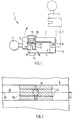
- FIG 1 shows schematically a side view of an embodiment a swirling device 1 which a Housing 3 includes, here several, a total of two housing parts 5 and 25.
- the second housing part 25 is by means of a hinge 9 via a swivel arm 7 rotatable on the first housing part 5 hinged and thus forms a cover.
- Handle 11 is the second housing part 25 with its solid position shown in solid lines his open position shown in dashed lines in Figure 1 folded.
- the swirling device 1 further comprises a Housing 3 penetrating straight yarn channel 13 of the Housing parts 5, 25 is formed. If the second housing part 25 is in its closed position is the yarn channel 13 circumferentially with the exception of the opening cross-section a blow nozzle arrangement, not shown, closed and only at its inlet mouth and its outlet mouth open. To a multifilament yarn, not shown in Figure 1 to be able to insert into or take out the thread channel 13, without first cutting it, the second housing part 25 folded up, so that the yarn channel 13 over its entire length is exposed.
- the blow nozzle arrangement is via a feed line 14 connected to a medium supply, by means of which the blow nozzle arrangement with a medium under pressure, preferably air, can be acted upon.
- the multifilament yarn is when passing through the straight yarn channel 13 with a Medium flow acts on the filaments with each other swirled, whereupon in the following with reference to FIGS. 2 to 23 is discussed in more detail.
- a yarn guide 19 is attached on the second housing part 25 .
- the yarn channel 13 is in this embodiment first housing part 5 incorporated in the form of a groove a semicircular, clear, constant along its length Has cross section.
- the ceiling 23 of the yarn channel 13 is from the flat underside of one attached to the swivel arm 7, second housing part 25 is formed.
- the cross-sectional shape of the Yarn channel 13 can also be designed differently.
- Figure 2 shows schematically a plan view of the first housing part 5 of the swirling device 1, in which the Yarn channel 13 is incorporated. This is based on its longitudinal central axis 26 transverse to the running direction of the filaments seen (arrow 27) - in two imaginary, hatched representations Areas divided, namely in a middle Area 29 and in outer edge areas 33, which between the Edges of the yarn channel 13 and the central region 29 are.
- the edge regions 33 are also referred to as dead zones.
- the opening cross section 37 of the blowing nozzle arrangement shown in FIG formed such that the 13th inflowing medium flow in one main flow and in two Secondary streams is shared.
- the main stream H flows into the middle, central area 29 and divided by the Impact against the underside of the housing part or cover 25 in two partial flow vortices with different directions of rotation (Figure 23) showing the desired local twists / entanglements of the filaments of the multifilament yarn.
- the filament twists can be different have local patterns, for example braided or Cable pattern.
- the two side streams N which are the actual Turbulence of the filaments practically does not contribute to the flow each in one of the edge areas 33 and guide the in the Edge areas 33 guided filaments in the middle area 29 of the yarn channel 13, where it is detected by the main stream H and to be swirled.
- This will increase the amount of time the Filaments in the edge areas 33 through the yarn channel 13 be guided, reduced so that non-vortexed, open Thread spots avoided, but at least be reduced.
- the swirling of the filaments takes place by means of the medium flow basically a structuring of the multifilament yarn instead, that is, by twisting the multifilament yarn also changed optically.
- This through the medium flow generated effects, for example swirl points and of individual filaments of the multifilament yarn Loops can be divided by the inventive Medium flow defined and influenced in several partial flows thereby be designed.
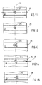
- Figures 3 to 15 Design variant of a blow nozzle arrangement explained in more detail, where the opening cross-section of a single blow nozzle 37 is formed.
- Figures 3 to 15 each show one Top view of an embodiment of the vertical in the Yarn channel 13 opening blow nozzle 37.
- the not shown Multifilament yarn passes through the yarn channel 13 in the direction an arrow 27, that is to say as shown in FIGS 15 from right to left.
- Figure 3 shows a blow nozzle 37a, the opening cross section symmetrical to the longitudinal central axis 26 of the yarn channel 13 and a transverse axis 41 is formed, which with the longitudinal central axis 26 a right angle, ie an angle of 90 ° includes.
- connection areas of the imaginary beams are rounded in such a way that they extend to the edges 33 of the yarn channel 13 extending partial opening cross sections of the blow nozzle 37a are smaller than that in the central region 29 located partial opening cross section of the blowing nozzle 37a.
- the main stream H defines the middle range.
- the cross sections for the main stream H are chosen so that the main flow H always a larger volume flow of the medium leads to each of the side streams N.
- the secondary regions flowing into the edge regions 33 of the yarn channel 13 N ensure that the swirling into the edge areas guided filaments back in as soon as possible reach the middle area 29. This will increase the amount of time in which the filaments are located in the edge area, in where there is practically no turbulence. It a very good swirl result is achieved by the Reduced number of open swirls and the lengths of these stolen stones are shortened.
- Figure 4 shows a blow nozzle 37b, the opening cross section in the is substantially V-shaped, being between the legs respectively Arms of the V-shape a gain 61 of the main stream H is provided.
- the V-shape in essentially changed to a W-shape, which together with a triangle forms the opening cross-section.
- the arms of the V shape or the W-shape also reach here Edge regions 33 of the yarn channel 13.
- Figure 5 shows a blow nozzle 37c, which is essentially one has cross-shaped or X-shaped opening cross section.
- the lying X has one on the longitudinal central axis 26 of the Yarn channel 13 lying center beam 45, which is the main stream H leads and is wider than that to the edge areas 33 protruding crossbars 47 and 49, which are the secondary flows there H lead.
- the blow nozzle 37c is symmetrical to that Longitudinal central axis 26 and the transverse axis 41 are formed. From the crossbar 47, 49 of the cross-shaped opening cross section outflowing side streams each have a smaller one Volume flow to than from the central area of the opening cross-section, that is, from the center beam 45 formed main opening.
- the blow nozzle 37d shown in FIG. 6 has a triangular one Opening cross-section and is in the yarn channel 13th arranged that one of two sides of the equilateral here Triangle-shaped tip 51 on the longitudinal central axis 26 of the Yarn channel 13 is.
- the blow nozzle 37d is symmetrical to Longitudinal central axis 26 formed. That in the direction of arrow 27 multifilament yarn passed through the yarn channel 13 initially hits on the in the area of the tip 51 of the opening cross section emerging main stream H, which becomes increasingly larger, and then by the side streams from the area of Tips 51 'and 51' 'of the triangular opening cross section emanate.
- the blowing nozzle 37e shown in FIG. 7 also has one triangular opening cross-section, with its on the Longitudinal central axis 26 lying on two sides of the broad, isosceles triangle tip 53 formed from the central area of the opening cross section of the blowing nozzle 37e outflowing main stream - in the direction of the multifilament yarn seen (arrow 27) - is subordinate.
- the multifilament yarn is therefore first of all on the broad base of the Triangular led.
- blow nozzle 37d a more intense and more uniform interlacing of the filaments with longer interlacing knots achieved.
- the opening cross section of the Blowing nozzle 37e is - as in all other exemplary embodiments the blow nozzle according to the invention symmetrical to the longitudinal central axis 26 trained.
- Figure 8 shows a blow nozzle 37f, which has a triangular opening cross section has, the triangle isosceles and compared to the triangles shown in Figures 6 and 7 is very narrow. This is the middle of the opening cross-section the blow nozzle 37f very pronounced, in particular compared to those in the edge regions 33 of the yarn channel 13 protruding edge zones of the opening cross section. Thereby the main flow is strong compared to the secondary flow pair.
- the tip 55 formed lies on the longitudinal central axis 26, that the multifilament yarn passed through the yarn channel 13 is first detected by the main stream, but also at the same time the paired sidestream is effective in the range of the base side of the isosceles triangle formed partial opening cross section into the edge regions 33 of the yarn channel 13 flows.
- Figure 9 shows a blow nozzle 37g, which has a T-shaped opening cross section having, that of the crossbar 57 of T-shaped partial opening cross section that of the longitudinal beam 59 of the T-shaped partial opening cross-section
- the crossbar 57 which is narrower than that Longitudinal bar 59 extends into the edge areas 33 of the yarn channel 13.
- the incoming multifilament yarn thus reaches first the "wide" side of the T-shaped opening cross-section, in which main and secondary flow act. This causes a more even swirling occurs because at the same time due to the bypass pair, the multifilament yarn dodges prevented in the dead zones 33 by the bypass pair becomes.
- Figure 10 shows a blow nozzle 37h, the opening cross section has a Y-shape, the substantially V-shaped part the Y-shape the part formed by a straight bar -in Direction of travel of the multifilament yarn seen (arrow 27) - upstream is.
- the ends of the V-shaped part of the Y-shape extend far into the edge zones 33 of the yarn channel 13 the filaments of the thread through the yarn channel 13 Multifilament yarns in the edge areas 33 from those from the V-shaped Exiting part of the opening cross section of the blow nozzle 37h Secondary streams recorded first and in the middle Area 29 of the yarn channel 13 passed.
- the blow nozzle 37i shown in FIG. 11 differs of the blowing nozzle 37h shown in FIG. 10 only because that the Y-shape of the opening cross-sectional area is changed is.
- the legs of the Letters have an oblique course, so that this not quite as far into the edge regions 33 of the yarn channel 33 extend as the legs of the shown in Figure 10 Y-shaped opening cross section.
- FIG. 12 shows a blow nozzle 37k, which has an opening cross section has that of a third embodiment is derived from a Y shape.
- the symmetrical to the longitudinal central axis 26 trained longitudinal beams of the Y-shape is opposite Y shapes shown in Figures 10 and 11 wider. Farther the free end of the longitudinal beam is relatively short and wedge-shaped.
- the blow nozzle 371 shown in FIG. 13 has a fish-shaped one Opening cross section on that of an ellipse and two legs forming a V-shape is derived.
- the both legs extend into the edge regions 33 of the yarn channel 13, while the ellipse with its large semiaxis on the longitudinal central axis 26 of the yarn channel 13 and thus the Main stream forms.
- FIG. 14 shows a blow nozzle 37m which has an opening cross section with a curved V-shape.
- swinging is understood to mean that the legs of the V-shape are not straight, but have a curvature, respectively are bent.
- all corners of the opening cross section the blow nozzle 37m rounded or point - according to a further embodiment, not shown Radius on.
- the opening cross section is in the middle Area 29 of the yarn channel 13 widened. Because in this embodiment the legs protrude far into the edge areas, the filaments are quickly transported out of the dead zones.
- the blow nozzle 37n shown in FIG. 15 has a opening cross-section essentially derived from a triangle on the two V-shaped arms which extends into the edge regions 33 of the yarn channel 13 protrude.
- FIGS. 16 to 19 each show a top view of the opening cross section of a further embodiment with a blowing nozzle arrangement 35, in which the opening cross section of several, here in each case a total of three blow nozzles 37/1, 37/2, 37/3 is formed. These open away from each other in the yarn channel 13 and each have a partial opening cross section on, which together the opening cross section of the Form blow nozzle assembly 35.
- the partial opening cross section of the Blower nozzle 37/1, from which the main flow of the medium flow into the Flowing yarn channel 13 is larger than that of the blowing nozzles 37/2 and 37/3, from which the bypasses of the medium flow escape.
- the blow nozzle arrangement is the opening cross section of all Embodiments - looking in the direction of Axis of the blowing duct opening into the thread duct - symmetrical to the longitudinal central axis 26 of the yarn channel 13.
- the partial opening cross sections of those shown in FIG. 16 Blow nozzles 37/1 to 37/3 are circular.
- the blow nozzles 37/2 and 37/3, from each of which a secondary flow into the yarn channel 13 flows in are in the direction of the multifilament yarn seen (arrow 27) - upstream of the blow nozzle 37/1.
- the blow nozzles 37/2, 37/3 each lie in one of the edge areas 33 of the yarn channel 13.
- the exemplary embodiment of the blow nozzle arrangement shown in FIG. 17 35 differs from that in FIG. 16 illustrated embodiment only in that the Partial cross sections of the bias nozzles 37/1 to 37/3 elliptical are trained.
- the major semi-axis of the Partial cross-section of the blow nozzle 37/1 forming ellipse lies on the longitudinal central axis 26.
- the major semiaxes of the compared to the partial opening cross section of the blow nozzle 37/1 blow nozzles each having smaller cross-sectional areas 37/2, 37/3 run perpendicular to the longitudinal central axis 26.
- Figure 18 shows an embodiment of the blow nozzle arrangement 35, in which the opening cross section of a triangular and two elliptical partial opening cross sections is formed.
- the blow nozzle 37/1 which has a triangular partial opening cross section has - is in the running direction of the multifilament yarn seen (arrow 27) - upstream of the blow nozzles 37/2, 37/3, such that one side of the partial opening cross section is parallel to the transverse axis 41.
- this this is done by the Yarn channel 13 guided multifilament yarn first, so that at the same time the main flow and a secondary flow pair to the effect come.
- the exemplary embodiment of the blow nozzle arrangement shown in FIG. 19 35 comprises two blow nozzles 37/2, 37/3, the Partial cross sections are elliptical and a blow nozzle 37/1, the partial opening cross section of a V-shape with a Center extension 65 has. This increases the partial opening cross section.
- the blow nozzles 37/2 and 37/3 from which each a secondary flow of the medium flow into the yarn channel 13 inflow, the blow nozzle 37/1 in the direction of the Multifilament yarns seen upstream, so first one Sidestream pair is effective. Since the blow nozzle 37/1 with their Partial opening cross sections into the edge areas 33 of the Yarn channel 13 is enough, then almost sets with the main stream at the same time again a secondary flow pair.
- the partial opening cross sections the blow nozzles 37/1, 3 // 2, 37/3 together the opening cross-section of the blow nozzle arrangement, the symmetry with the longitudinal central axis 26 of the yarn channel 13 preserved.
- the opening cross section shown with sharp corners or edges these corners have a fillet radius, currently in one area for manufacturing reasons from 0.03 mm to 0.20 mm.
- the blow nozzles from which the side streams of the The medium flow flows into the yarn channel 13 are upstream. That is, the filaments of the multifilament yarn are initially from the side streams in the Edge areas 33 of the yarn channel 13 are detected and only then of the inflowing in the central region 29 of the yarn channel 13 Mainstream swirled. In the embodiment according to FIG. 18, the filaments are caught by the main stream, but also from the side streams.
- the subordinate Bypass flow pair of blow nozzles 37/2 and 37/3 reinforces the Sidelux effect without affecting the main flow.
- the Figure 20 shows a plan view of an embodiment of the Blower nozzle arrangement 35, in which the longitudinal central axis 26 symmetrical opening cross-section formed by a blow nozzle 37o is.
- the opening cross section of the blow nozzle 37o settles composed of two imaginary partial opening cross sections, the are interconnected.
- the first partial opening cross section is essentially C-shaped and extends directly to the edges of the yarn channel 13. This partial opening cross-section is seen in the direction of the multifilament yarn (Arrow 27) - the elliptical second partial opening cross section subordinate, from which only the main flow of the medium flow flows into the yarn channel 13.
- the in the area the transverse axis 41 is the width of the opening cross section less than in the upstream and downstream Area.
- the main stream is divided into two main streams divided, locally and - according to a preferred embodiment variant - also on the multi-parliamentary thread one after the other Act.
- the main flow of the medium flow in more than two, i.e. divided into at least three main sub-streams.
- the "division" is not to be understood physically, but takes place in particular through the design of the Opening cross section, such as that in Figure 20 illustrated embodiment realized.
- FIG. 21 shows another embodiment variant of that in FIG. 20 Blow nozzle arrangement 35 shown, in which the opening cross section is formed by two blow nozzles 37/1 and 37/2.
- the essentially C-shaped Blowing nozzle 37/2 is immediately upstream of blowing nozzle 37/1 and extends into the edge regions 33 of the yarn channel 13.
- the two main currents are therefore physically separate from one another separated, that is, the first main stream with the Secondary streams and the second main stream become two from each other separate blowing nozzles blown into the yarn channel 13.
- FIG. 22 shows a sectional view of an embodiment of the Yarn channel 13 through which a multifilament yarn shown in dashed lines 69 is performed.
- One opens into the yarn channel 13 Blowing nozzle 37, the opening cross section of which is variable and for example from one based on the previous FIGS. 3 to 21 shown cross sections are formed can.
- the blowing nozzle 37 is opposite the longitudinal central axis 26 of the yarn channel 13 inclined by an angle ⁇ between the Axis 71 of the blow nozzle 37 and the longitudinal central axis 26 of the Yarn channel 13 is measured.
- the blowing nozzle 37 inclined by an angle ⁇ with respect to the longitudinal central axis 26, that in a range of 60 ° ⁇ ⁇ ⁇ 90 °, preferably from 75 ° ⁇ ⁇ ⁇ 87 °. It has been found that through the Defined inclination of the blow nozzle 37, the swirl result can also be influenced.
- Figures 3 to 21 illustrated embodiments of the Blower nozzle arrangement 35 is the angle ⁇ -as described above- merely by way of example 90 °. To make an optical change, thus structuring the multifilament yarn generate, it has proven to be particularly advantageous Angle ⁇ ⁇ 60 ° to choose.
- This can, for example Loops and other structures of the filaments in the desired Generated way.
- the invention can thus also Texturing filament yarns can be used with success. It has been shown that, as a rule, by the inclination of the Blowing nozzle in the running direction of the multifilament yarn 69, in particular for textured yarns and for texturing yarns a better swirl result can be achieved than with an inclination of the blowing nozzle 37 against the direction of the Multifilament yarn. However, that is enough with one against the Direction of rotation of the multifilament yarn inclined blowing nozzle 37 achievable swirling result in many cases the requirements so that basically the inclination of the blowing nozzle 37th is practically arbitrary.
- the multiple blow nozzles 37 has, as for example with reference to Figures 16 to 19 and 20, 21 described, the blow nozzles 37/1, 37/2 and 37/3 different from the longitudinal central axis 26 of the yarn channel 13 be inclined, i.e. different angles ⁇ exhibit.
- the main flow and the secondary flows act here in different directions, but still in essentially the same sense of what an optimal coordination of Operation of the partial flows of the medium flow enables.
- FIG. 23 one is based on a schematic cross section Swirling device the mode of action in the yarn channel 13 inflowing main stream H and the secondary streams N des Medium flow shown.
- main and side streams are not physically separate from one another Cut.
- the functional representation is on physically separate main and secondary flows without further ado transferable.
- the blowing nozzle opens at the bottom of the semi-circular yarn channel 13 in the middle area, in which the one indicated by an arrow H.
- Main flow of the medium flow flows in and on impact splits into two partial flow vortices on the cover plate 25, which have an opposite sense of rotation.
- the filaments of the multifilament yarn become partial flow eddies swirled intensely, so that strong swirling points or Swirl nodes are formed.
- FIGS. 1 to 23 shows a Process for the treatment of filament yarns in order to swirl. It consists of turning the medium flow into a main flow and split into pairs of side streams, the Main stream in the middle area of the yarn channel and the one of the side streams in one edge area and the other the secondary flows in the other edge region of the yarn channel be initiated. Main and secondary flows are essentially directed in the same direction so that their directions do not cross. A certain different direction of Media flows H and N are permitted, provided that these directions each within areas 29 and 33 (FIG. 2) lie. The main stream is said to be generally opposite each of the both side flows lead the larger volume flow for themselves.
- the time period in which the There are filaments in the edge areas of the yarn channel decrease so that the result of the turbulence is positively influenced. It can be done this way Limit open swirls of yarn to certain sizes. Also the number of knots, the size and strength the same can be changed in a targeted manner. The width the middle area where the actual swirling takes place, as well as the remaining marginal areas in which No swirling occurs through the main stream certainly.
- the swirl quality is improved.
- medium consumption can be preferred reduced with a consistently good swirl result be so that the cost of turbulence can be reduced are.
- Through the effective interaction of the side streams with the main flow of the medium flow is an increase the running speed of the multifilament yarn and thus the Swirling device productivity possible.
Landscapes
- Engineering & Computer Science (AREA)
- Physics & Mathematics (AREA)
- Fluid Mechanics (AREA)
- Textile Engineering (AREA)
- Mechanical Engineering (AREA)
- Yarns And Mechanical Finishing Of Yarns Or Ropes (AREA)
- Spinning Or Twisting Of Yarns (AREA)
- Treatment Of Fiber Materials (AREA)
Description
- Figur 1
- eine Seitenansicht eines Ausführungsbeispiels einer Verwirbelungsvorrichtung;
- Figur 2
- eine schematische Draufsicht auf einen Garnkanal;
- Figuren 3 bis 15
- jeweils eine Draufsicht auf einen öffnungsquerschnitt einer ersten Ausführungsvariante der erfindungsgemäßen Blasdüsenanordnung, bei welcher Haupt- und Nebenströme durch die Gestaltung des Querschnitts einer Blasdüse erzeugt werden;
- Figuren 16 bis 19
- jeweils eine Draufsicht auf den öffnungsquerschnitt einer zweiten Ausführungsvariante der Blasdüsenanordnung, bei welcher Haupt- und Nebenströme körperlich getrennt sind;
- Figuren 20 und 21
- jeweils eine Draufsicht auf den öffnungsquerschnitt einer weiteren Ausführungsvariante der Blasdüsenanordnung mit zwei Hauptströmen;
- Figur 22
- eine Schnittansicht des Garnkanals;
- Figur 23
- einen schematischen Querschnitt der Verwirbelungsvorrichtung.
Claims (23)
- Vorrichtung zum Verwirbeln von Multifilamentgarnen, die einen Garnkanal aufweist, in dem die Filamente des Multifilamentgarnes mittels eines aus einem öffnungsquerschnitt einer Blasdüse austretenden Mediumstromes, insbesondere eines Druckluftstromes, verwirbelbar sind, wobei der öffnungsquerschnitt der Blasdüse im wesentlichen symmetrisch zur Längsachse des Garnkanals ausgebildet ist und einen Hauptstrom erzeugt, und paarweise Nebenströme vorgesehen sind, wobei der eine Nebenstrom in den einen Randbereich und der andere Nebenstrom in den anderen Randbereich des Garnkanals einströmt, dadurch gekenzeichnet, daß Haupt-(H) und Nebenströme (N) im wesentlichen gleichsinnig gerichtet sind.
- Verwirbelungsvorrichtung nach Anspruch 1, dadurch gekennzeichnet, daß der Mediumstrom durch den öffnungsquerschnitt einer Blasdüsenanordnung (35;37) in einen Hauptstrom (H) und in paarweise Nebenströme (N) aufgeteilt ist.
- Verwirbelungsvorrichtung nach einem der Ansprüche 1 oder 2, dadurch gekennzeichnet, daß der Hauptstrom (H) gegenüber jedem der beiden Nebenströme (N) den größeren Volumenstrom des Mediums führt.
- Verwirbelungsvorrichtung nach einem oder mehreren der Ansprüche 1 bis 3, dadurch gekennzeichnet, daß der öffnungsquerschnitt des Nebenstromes (N) vom öffnungsquerschnitt des Hauptstromes (H) getrennt ist.
- Verwirbelungsvorrichtung nach einem oder mehreren der Ansprüche 1 bis 4, dadurch gekennzeichnet, daß der Hauptstrom (H) in Laufrichtung der Filamente gesehen den Nebenströmen (N) nachgeordnet ist.
- Verwirbelungsvorrichtung nach Anspruch 5, dadurch gekennzeichnet, daß dem Hauptstrom (H) Nebenströme (N) nachgeordnet sind.
- Verwirbelungsvorrichtung nach einem oder mehreren der Ansprüche 1 bis 6, dadurch gekennzeichnet, daß der Hauptstrom (H) aus mehreren Teilströmen gebildet ist.
- Verwirbelungsvorrichtung nach einem oder mehreren der Ansprüche 1 bis 7, dadurch gekennzeichnet, daß der Nebenstrom (N) im Randbereich (33) des Garnkanals (13) bis außerhalb des Garnkanals (13) unter die Deckplatte (25) reicht.
- Verwirbelungsvorrichtung nach einem oder mehreren der Ansprüche 1 bis 8, dadurch gekennzeichnet, daß der Öffnungsquerschnitt symmetrisch oder im wesentlichen symmetrisch zu einer Querachse (41) ist, die mit der Längsmittelachse (26) einen rechten Winkel einschließt.
- Verwirbelungsvorrichtung nach einem oder mehreren der Ansprüche 1 bis 8, dadurch gekennzeichnet, daß der Öffnungsquerschnitt asymmetrisch zur Querachse (41) ausgebildet ist.
- Verwirbelungsvorrichtung nach einem oder mehreren der Ansprüche 1 bis 10, dadurch gekennzeichnet, daß der öffnungsquerschnitt Y-förmig (37h;...;37o;37/2) ausgebildet ist.
- Verwirbelungsvorrichtung nach einem oder mehreren der Ansprüche 1 bis 10, dadurch gekennzeichnet, daß der öffnungsquerschnitt kreuzförmig (37a) ausgebildet ist.
- Verwirbelungsvorrichtung nach einem oder mehreren der Ansprüche 1 bis 10, dadurch gekennzeichnet, daß der öffnungsquerschnitt dreieckförmig (37d;...;37f) ausgebildet ist.
- Verwirbelungsvorrichtung nach einem oder mehreren der Ansprüche 1 bis 10, dadurch gekennzeichnet, daß der öffnungsquerschnitt T-förmig (37g) ausgebildet ist.
- Verwirbelungsvorrichtung nach einem oder mehreren der Ansprüche 1 bis 10, dadurch gekennzeichnet, daß der öffnungsquerschnitt X-förmig (37c) ausgebildet ist.
- Verwirbelungsvorrichtung nach einem oder mehreren der Ansprüche 1 bis 15, dadurch gekennzeichnet, daß die Blasdüse (37a;37b;...;37q;37/1;37/2;37/3) gegenüber der Längsmittelachse (26) um einen Winkel δ geneigt ist, der in einem Bereich von 60° ≤ δ ≤ 90 °, vorzugsweise von 75° ≤ δ ≤ 87° liegt.
- Verwirbelungsvorrichtung nach einem oder mehreren der Ansprüche 1 bis 15, dadurch gekennzeichnet, daß die Blasdüse (37a;37b;...;37q;37/1;37/2;37/3) gegenüber der Längsmittelachse 826) um einen Winkel δ < 60° geneigt ist.
- Verfahren zum Verwirbeln von mindestens einem Multifilamentgarn, dessen Filamente in einem Garnkanal mittels eines Mediumstromes, insbesondere Druckluftstromes verwirbelt werden und der Mediumstrom in einen Hauptstrom und in paarweise Nebenströme aufgeteilt wird, wobei der Hauptstrom in den mittleren Bereich des Garnkanals und der eine der Nebenströme in den einen Randbereich und der andere der Nebenströme in den anderen Randbereich des Garnkanals eingeleitet werden, dadurch gekennzeichnet, daß Haupt- und Nebenströme im wesentlichen gleichsinnig gerichtet sind.
- Verfahren nach Anspruch 18, dadurch gekennzeichnet, daß der Hauptstrom (H) gegenüber jedem der beiden Nebenströme (N) den größeren Volumenstrom führt.
- Verfahren nach einem der Ansprüche 18 oder 19, dadurch gekennzeichnet, daß mittels des Hauptstromes (H) die Breite des mittleren Bereiches (29) gegenüber den Randbereichen (33) bestimmt wird.
- Verfahren nach einem oder mehreren der Ansprüche 18 bis 20, dadurch gekennzeichnet, daß die Größe der Nebenströme (N) gegenüber dem Hauptstrom (H) derart abgestimmt wird, daß die Zeitdauer, in der die Filamente in den Randbereichen (33) des Garnkanales (13) sich befinden, verringert wird, so daß unverwirbelte offene Garnstellen auf bestimmte Größen beschränkt werden.
- Verfahren nach einem oder mehreren der Ansprüche 18 bis 21, dadurch gekennzeichnet, daß die Nebenströme (N) örtlich getrennt vom Hauptstrom (H) zur Einwirkung auf das zu verwirbelnde Filamentgarn kommen.
- Verfahren nach Anspruch 22, dadurch gekennzeichnet, daß die paarweisen Nebenströme (N) im wesentlichen vor dem Hauptstrom (H) zur Einwirkung auf das zu verwirbelnde Filamentgarn kommen.
Applications Claiming Priority (3)
| Application Number | Priority Date | Filing Date | Title |
|---|---|---|---|
| DE19745182A DE19745182C2 (de) | 1997-10-13 | 1997-10-13 | Verfahren und Vorrichtung zum Verwirbeln von Multifilamentgarnen |
| DE19745182 | 1997-10-13 | ||
| PCT/DE1998/002998 WO1999019549A2 (de) | 1997-10-13 | 1998-10-09 | Garnverwirbelungsvorrichtung |
Publications (2)
| Publication Number | Publication Date |
|---|---|
| EP1030938A2 EP1030938A2 (de) | 2000-08-30 |
| EP1030938B1 true EP1030938B1 (de) | 2002-04-10 |
Family
ID=7845404
Family Applications (1)
| Application Number | Title | Priority Date | Filing Date |
|---|---|---|---|
| EP98961002A Expired - Lifetime EP1030938B1 (de) | 1997-10-13 | 1998-10-09 | Garnverwirbelungsvorrichtung und verfahren zum verwirbeln von multifilamentgarnen |
Country Status (6)
| Country | Link |
|---|---|
| US (1) | US6112386A (de) |
| EP (1) | EP1030938B1 (de) |
| JP (1) | JP3656954B2 (de) |
| DE (2) | DE19745182C2 (de) |
| TW (1) | TW494150B (de) |
| WO (1) | WO1999019549A2 (de) |
Cited By (1)
| Publication number | Priority date | Publication date | Assignee | Title |
|---|---|---|---|---|
| DE102012003410A1 (de) | 2012-02-23 | 2013-08-29 | Rpe Technologies Gmbh | Garnbehandlungsvorrichtung |
Families Citing this family (3)
| Publication number | Priority date | Publication date | Assignee | Title |
|---|---|---|---|---|
| DE50211888D1 (de) * | 2001-09-29 | 2008-04-24 | Oerlikon Heberlein Temco Wattw | Verfahren und vorrichtung zur herstellung von kontengarn |
| IT1393810B1 (it) * | 2009-04-29 | 2012-05-11 | Technores S R L C O Studio Minicucci Pidatella & A | Dispositivo per il trattamento di un filato, sistema di trattamento di un filato e metodo per il trattamento di un filato |
| EP3954814A1 (de) * | 2020-08-10 | 2022-02-16 | Heberlein AG | Verwirbelungsdüse für die herstellung von garnen mit knoten und verfahren zum verwirbeln von garn |
Family Cites Families (17)
| Publication number | Priority date | Publication date | Assignee | Title |
|---|---|---|---|---|
| US2985995A (en) * | 1960-11-08 | 1961-05-30 | Du Pont | Compact interlaced yarn |
| US3262179A (en) * | 1964-12-01 | 1966-07-26 | Du Pont | Apparatus for interlacing multifilament yarn |
| GB1127023A (en) * | 1965-03-08 | 1968-09-11 | Lepetit Spa | Process for preparing pyridoxine and derivatives thereof |
| FR1556272A (de) * | 1967-11-30 | 1969-02-07 | ||
| US3730413A (en) * | 1971-05-10 | 1973-05-01 | Ici Ltd | Interlacing jet |
| DE2217109C3 (de) * | 1972-04-10 | 1979-04-12 | Hoechst Ag, 6000 Frankfurt | Verfahren und Vorrichtung zum Kräuseln von Fäden und Garnen |
| US3751775A (en) * | 1972-06-07 | 1973-08-14 | Allied Chem | Apparatus and process for commingling multifilament yarn |
| JPS5212362A (en) * | 1975-07-18 | 1977-01-29 | Toray Industries | Fluid treatment apparatus |
| IT1093498B (it) * | 1977-03-30 | 1985-07-19 | Toray Industries | Metodo ed apparecchio per intreociare un filo a molti filamenti |
| US4251904A (en) * | 1978-11-08 | 1981-02-24 | Toray Industries, Inc. | Yarn treating apparatus |
| US4639986A (en) * | 1981-04-01 | 1987-02-03 | Phillips Petroleum Company | Filament jet entangler |
| DE3711759C2 (de) * | 1986-04-08 | 1994-02-17 | Inst Textil & Faserforschung | Garnverwirbelungsvorrichtung |
| US4965916A (en) * | 1987-08-15 | 1990-10-30 | Deutsche Institute Fur Textil- Und Faserforschung Stuttgart Stiftung Des Offentlichenrechts | Means for the interlacing of yarn |
| DE4113927A1 (de) * | 1991-04-29 | 1992-11-05 | Kugelfischer G Schaefer & Co | Verwirbelungsduese |
| US5325572A (en) * | 1992-06-23 | 1994-07-05 | E. I. Du Pont De Nemours And Company | Yarn treating jet |
| DE69316491T2 (de) * | 1992-09-04 | 1998-05-07 | Toray Industries | Vorrichtung zur Behandlung eines Garnes mit einer Flüssigkeit |
| CH687086A5 (de) * | 1993-05-11 | 1996-09-13 | Heberlein & Co Ag | Vorrichtung zum Behandeln wenigstens eines laufenden Multifilamentgarns. |
-
1997
- 1997-10-13 DE DE19745182A patent/DE19745182C2/de not_active Expired - Fee Related
-
1998
- 1998-10-09 WO PCT/DE1998/002998 patent/WO1999019549A2/de not_active Ceased
- 1998-10-09 JP JP2000516094A patent/JP3656954B2/ja not_active Expired - Fee Related
- 1998-10-09 US US09/169,096 patent/US6112386A/en not_active Expired - Lifetime
- 1998-10-09 EP EP98961002A patent/EP1030938B1/de not_active Expired - Lifetime
- 1998-10-09 DE DE59803781T patent/DE59803781D1/de not_active Expired - Lifetime
- 1998-10-12 TW TW087116863A patent/TW494150B/zh not_active IP Right Cessation
Cited By (1)
| Publication number | Priority date | Publication date | Assignee | Title |
|---|---|---|---|---|
| DE102012003410A1 (de) | 2012-02-23 | 2013-08-29 | Rpe Technologies Gmbh | Garnbehandlungsvorrichtung |
Also Published As
| Publication number | Publication date |
|---|---|
| TW494150B (en) | 2002-07-11 |
| US6112386A (en) | 2000-09-05 |
| WO1999019549A3 (de) | 1999-07-08 |
| JP3656954B2 (ja) | 2005-06-08 |
| EP1030938A2 (de) | 2000-08-30 |
| JP2001520325A (ja) | 2001-10-30 |
| DE19745182C2 (de) | 2000-05-18 |
| DE59803781D1 (de) | 2002-05-16 |
| DE19745182A1 (de) | 1999-04-15 |
| WO1999019549A2 (de) | 1999-04-22 |
Similar Documents
| Publication | Publication Date | Title |
|---|---|---|
| EP0465407B1 (de) | Vorrichtung zum Verwirbeln von Multifilamentgarnen | |
| EP0880611B1 (de) | Verfahren zum aerodynamischen texturieren, texturierdüse, düsenkopf sowie verwendung | |
| DE3612229C2 (de) | ||
| EP1436451B1 (de) | Verfahren und vorrichtung zur herstellung von kontengarn | |
| EP0046278B1 (de) | Einrichtung zum Herstellen von Fixpunkt-Multifilamentgarnen | |
| CH687086A5 (de) | Vorrichtung zum Behandeln wenigstens eines laufenden Multifilamentgarns. | |
| EP0326552B1 (de) | Garnverwirbelungsvorrichtung | |
| DE19745182C2 (de) | Verfahren und Vorrichtung zum Verwirbeln von Multifilamentgarnen | |
| DE3623965A1 (de) | Vorrichtung zur behandlung von textilgarnen | |
| DE3823725A1 (de) | Universalverfahren zum aufdrehen, entwirren und oeffnen eines textilgarns und vorrichtung zur durchfuehrung des verfahrens | |
| DE2701053A1 (de) | Luftduesenvorrichtung zur herstellung von verdrilltem garn sowie verfahren zum verdrillen der faeden von aus mehreren faeden gebildetem garn | |
| DE3011763A1 (de) | Spinnverfahren zum erzeugen von vielfachverbundfasern | |
| DE3626374A1 (de) | Mischkopf fuer druckluftunterstuetzte textilgarnverbindungsgeraete | |
| DE3010387C2 (de) | Luftdüse zum Erzeugen verwirbelten mehrfädigen Garns | |
| WO1996033304A1 (de) | Webmaschine | |
| EP4053320B1 (de) | Düsenstreifen zur erzeugung von fluidstrahlen zur hydrodynamischen verfestigung einer materialbahn sowie anlage zur verfestigung einer solchen | |
| DE69316534T2 (de) | Vorrichtung zur Behandlung eines Garnes mit einer Flüssigkeit | |
| DE69810343T2 (de) | Einzelaufpralldüse zum bauschen von garnen | |
| EP2886690B1 (de) | Düse und verfahren zur herstellung von knotengarn | |
| DE3318494C2 (de) | Vorrichtung zum Texturieren eines Fadens | |
| DE1785442A1 (de) | Verfahren und Vorrichtung zur Garnbehandlung | |
| DE4222662B4 (de) | Vorrichtung zum Vorbereiten von Fadenenden | |
| DE19947894C1 (de) | Vorrichtung zum Verwirbeln von Multifilamentgarnen | |
| DE19700817C2 (de) | Verfahren und Verwirbelungsdüse zur Herstellung von spinntexturierten Filamentgarnen | |
| DE3527415C2 (de) |
Legal Events
| Date | Code | Title | Description |
|---|---|---|---|
| PUAI | Public reference made under article 153(3) epc to a published international application that has entered the european phase |
Free format text: ORIGINAL CODE: 0009012 |
|
| 17P | Request for examination filed |
Effective date: 20000511 |
|
| AK | Designated contracting states |
Kind code of ref document: A2 Designated state(s): CH DE FR GB IT LI |
|
| GRAG | Despatch of communication of intention to grant |
Free format text: ORIGINAL CODE: EPIDOS AGRA |
|
| 17Q | First examination report despatched |
Effective date: 20010711 |
|
| GRAG | Despatch of communication of intention to grant |
Free format text: ORIGINAL CODE: EPIDOS AGRA |
|
| GRAH | Despatch of communication of intention to grant a patent |
Free format text: ORIGINAL CODE: EPIDOS IGRA |
|
| RTI1 | Title (correction) |
Free format text: DEVICE AND PROCESS FOR INTERMINGLING YARN |
|
| GRAH | Despatch of communication of intention to grant a patent |
Free format text: ORIGINAL CODE: EPIDOS IGRA |
|
| REG | Reference to a national code |
Ref country code: GB Ref legal event code: IF02 |
|
| GRAA | (expected) grant |
Free format text: ORIGINAL CODE: 0009210 |
|
| AK | Designated contracting states |
Kind code of ref document: B1 Designated state(s): CH DE FR GB IT LI |
|
| REG | Reference to a national code |
Ref country code: CH Ref legal event code: EP |
|
| REF | Corresponds to: |
Ref document number: 59803781 Country of ref document: DE Date of ref document: 20020516 |
|
| REG | Reference to a national code |
Ref country code: CH Ref legal event code: NV Representative=s name: SPIERENBURG HELMLE-KOLB & PARTNER AG PATENT- UND M |
|
| GBT | Gb: translation of ep patent filed (gb section 77(6)(a)/1977) |
Effective date: 20020729 |
|
| ET | Fr: translation filed | ||
| PLBE | No opposition filed within time limit |
Free format text: ORIGINAL CODE: 0009261 |
|
| STAA | Information on the status of an ep patent application or granted ep patent |
Free format text: STATUS: NO OPPOSITION FILED WITHIN TIME LIMIT |
|
| 26N | No opposition filed |
Effective date: 20030113 |
|
| REG | Reference to a national code |
Ref country code: CH Ref legal event code: PCAR Free format text: SPIERENBURG & PARTNER AG, PATENT- UND MARKENANWAELTE;MELLINGERSTRASSE 12;5443 NIEDERROHRDORF (CH) |
|
| PGFP | Annual fee paid to national office [announced via postgrant information from national office to epo] |
Ref country code: DE Payment date: 20130924 Year of fee payment: 16 Ref country code: FR Payment date: 20131028 Year of fee payment: 16 Ref country code: CH Payment date: 20131024 Year of fee payment: 16 Ref country code: GB Payment date: 20131029 Year of fee payment: 16 |
|
| PGFP | Annual fee paid to national office [announced via postgrant information from national office to epo] |
Ref country code: IT Payment date: 20131023 Year of fee payment: 16 |
|
| REG | Reference to a national code |
Ref country code: DE Ref legal event code: R119 Ref document number: 59803781 Country of ref document: DE |
|
| REG | Reference to a national code |
Ref country code: CH Ref legal event code: PL |
|
| GBPC | Gb: european patent ceased through non-payment of renewal fee |
Effective date: 20141009 |
|
| PG25 | Lapsed in a contracting state [announced via postgrant information from national office to epo] |
Ref country code: LI Free format text: LAPSE BECAUSE OF NON-PAYMENT OF DUE FEES Effective date: 20141031 Ref country code: GB Free format text: LAPSE BECAUSE OF NON-PAYMENT OF DUE FEES Effective date: 20141009 Ref country code: CH Free format text: LAPSE BECAUSE OF NON-PAYMENT OF DUE FEES Effective date: 20141031 Ref country code: DE Free format text: LAPSE BECAUSE OF NON-PAYMENT OF DUE FEES Effective date: 20150501 |
|
| REG | Reference to a national code |
Ref country code: FR Ref legal event code: ST Effective date: 20150630 |
|
| PG25 | Lapsed in a contracting state [announced via postgrant information from national office to epo] |
Ref country code: FR Free format text: LAPSE BECAUSE OF NON-PAYMENT OF DUE FEES Effective date: 20141031 Ref country code: IT Free format text: LAPSE BECAUSE OF NON-PAYMENT OF DUE FEES Effective date: 20141009 |