EP1030383A2 - Structure à transport de charges - Google Patents
Structure à transport de charges Download PDFInfo
- Publication number
- EP1030383A2 EP1030383A2 EP00301196A EP00301196A EP1030383A2 EP 1030383 A2 EP1030383 A2 EP 1030383A2 EP 00301196 A EP00301196 A EP 00301196A EP 00301196 A EP00301196 A EP 00301196A EP 1030383 A2 EP1030383 A2 EP 1030383A2
- Authority
- EP
- European Patent Office
- Prior art keywords
- layer
- dopant
- organic
- transport
- charge
- Prior art date
- Legal status (The legal status is an assumption and is not a legal conclusion. Google has not performed a legal analysis and makes no representation as to the accuracy of the status listed.)
- Withdrawn
Links
- 229920000642 polymer Polymers 0.000 claims abstract description 79
- 239000000758 substrate Substances 0.000 claims abstract description 30
- 239000002904 solvent Substances 0.000 claims abstract description 19
- 230000005693 optoelectronics Effects 0.000 claims abstract description 18
- 230000005525 hole transport Effects 0.000 claims abstract description 15
- 238000005215 recombination Methods 0.000 claims abstract description 7
- 239000010410 layer Substances 0.000 claims description 264
- 239000002019 doping agent Substances 0.000 claims description 147
- 238000009792 diffusion process Methods 0.000 claims description 37
- 238000000034 method Methods 0.000 claims description 35
- 239000012044 organic layer Substances 0.000 claims description 35
- 239000000463 material Substances 0.000 claims description 27
- 239000002243 precursor Substances 0.000 claims description 21
- 238000000151 deposition Methods 0.000 claims description 12
- 238000007641 inkjet printing Methods 0.000 claims description 12
- 238000004519 manufacturing process Methods 0.000 claims description 12
- 230000008021 deposition Effects 0.000 claims description 10
- 239000011521 glass Substances 0.000 claims description 10
- 230000002209 hydrophobic effect Effects 0.000 claims description 9
- 230000003993 interaction Effects 0.000 claims description 6
- 239000011368 organic material Substances 0.000 claims description 6
- 238000007639 printing Methods 0.000 claims description 6
- 230000006798 recombination Effects 0.000 claims description 6
- 238000000926 separation method Methods 0.000 claims description 5
- 239000000443 aerosol Substances 0.000 claims description 4
- 238000002508 contact lithography Methods 0.000 claims description 4
- 238000004070 electrodeposition Methods 0.000 claims description 4
- 238000007590 electrostatic spraying Methods 0.000 claims description 4
- 238000007650 screen-printing Methods 0.000 claims description 4
- 238000005507 spraying Methods 0.000 claims description 4
- 239000002800 charge carrier Substances 0.000 claims description 3
- 229910052739 hydrogen Inorganic materials 0.000 claims description 3
- 239000001257 hydrogen Substances 0.000 claims description 3
- 230000031700 light absorption Effects 0.000 claims description 2
- 239000002356 single layer Substances 0.000 claims description 2
- 239000002131 composite material Substances 0.000 claims 2
- 239000000975 dye Substances 0.000 abstract description 37
- 229920000553 poly(phenylenevinylene) Polymers 0.000 description 20
- 239000004065 semiconductor Substances 0.000 description 15
- 230000015572 biosynthetic process Effects 0.000 description 9
- 239000000243 solution Substances 0.000 description 9
- 239000010408 film Substances 0.000 description 7
- 229910052751 metal Inorganic materials 0.000 description 7
- 239000002184 metal Substances 0.000 description 7
- 238000010791 quenching Methods 0.000 description 7
- 230000000171 quenching effect Effects 0.000 description 7
- WMAXWOOEPJQXEB-UHFFFAOYSA-N 2-phenyl-5-(4-phenylphenyl)-1,3,4-oxadiazole Chemical compound C1=CC=CC=C1C1=NN=C(C=2C=CC(=CC=2)C=2C=CC=CC=2)O1 WMAXWOOEPJQXEB-UHFFFAOYSA-N 0.000 description 5
- 239000004411 aluminium Substances 0.000 description 5
- 229910052782 aluminium Inorganic materials 0.000 description 5
- XAGFODPZIPBFFR-UHFFFAOYSA-N aluminium Chemical compound [Al] XAGFODPZIPBFFR-UHFFFAOYSA-N 0.000 description 5
- 150000004985 diamines Chemical class 0.000 description 5
- -1 poly(p-phenylene vinylene) Polymers 0.000 description 5
- 238000004528 spin coating Methods 0.000 description 5
- AZQWKYJCGOJGHM-UHFFFAOYSA-N 1,4-benzoquinone Chemical compound O=C1C=CC(=O)C=C1 AZQWKYJCGOJGHM-UHFFFAOYSA-N 0.000 description 4
- CSCPPACGZOOCGX-UHFFFAOYSA-N Acetone Chemical compound CC(C)=O CSCPPACGZOOCGX-UHFFFAOYSA-N 0.000 description 4
- 125000000129 anionic group Chemical group 0.000 description 4
- 201000000760 cerebral cavernous malformation Diseases 0.000 description 4
- 238000006243 chemical reaction Methods 0.000 description 4
- 239000007800 oxidant agent Substances 0.000 description 4
- 230000001590 oxidative effect Effects 0.000 description 4
- 229920003227 poly(N-vinyl carbazole) Polymers 0.000 description 4
- OKKJLVBELUTLKV-UHFFFAOYSA-N Methanol Chemical compound OC OKKJLVBELUTLKV-UHFFFAOYSA-N 0.000 description 3
- 229920001609 Poly(3,4-ethylenedioxythiophene) Polymers 0.000 description 3
- 239000007864 aqueous solution Substances 0.000 description 3
- 125000002091 cationic group Chemical group 0.000 description 3
- 239000011248 coating agent Substances 0.000 description 3
- 238000000576 coating method Methods 0.000 description 3
- 238000004132 cross linking Methods 0.000 description 3
- 238000010438 heat treatment Methods 0.000 description 3
- 239000011159 matrix material Substances 0.000 description 3
- 229920003229 poly(methyl methacrylate) Polymers 0.000 description 3
- 229920000767 polyaniline Polymers 0.000 description 3
- 239000004926 polymethyl methacrylate Substances 0.000 description 3
- 229920000123 polythiophene Polymers 0.000 description 3
- 230000008569 process Effects 0.000 description 3
- XLYOFNOQVPJJNP-UHFFFAOYSA-N water Substances O XLYOFNOQVPJJNP-UHFFFAOYSA-N 0.000 description 3
- 229940005561 1,4-benzoquinone Drugs 0.000 description 2
- UHXOHPVVEHBKKT-UHFFFAOYSA-N 1-(2,2-diphenylethenyl)-4-[4-(2,2-diphenylethenyl)phenyl]benzene Chemical group C=1C=C(C=2C=CC(C=C(C=3C=CC=CC=3)C=3C=CC=CC=3)=CC=2)C=CC=1C=C(C=1C=CC=CC=1)C1=CC=CC=C1 UHXOHPVVEHBKKT-UHFFFAOYSA-N 0.000 description 2
- OYPRJOBELJOOCE-UHFFFAOYSA-N Calcium Chemical compound [Ca] OYPRJOBELJOOCE-UHFFFAOYSA-N 0.000 description 2
- HEDRZPFGACZZDS-UHFFFAOYSA-N Chloroform Chemical compound ClC(Cl)Cl HEDRZPFGACZZDS-UHFFFAOYSA-N 0.000 description 2
- 239000011575 calcium Substances 0.000 description 2
- 229910052791 calcium Inorganic materials 0.000 description 2
- 239000013522 chelant Substances 0.000 description 2
- 238000010276 construction Methods 0.000 description 2
- 230000000694 effects Effects 0.000 description 2
- UKZQEOHHLOYJLY-UHFFFAOYSA-M ethyl eosin Chemical compound [K+].CCOC(=O)C1=CC=CC=C1C1=C2C=C(Br)C(=O)C(Br)=C2OC2=C(Br)C([O-])=C(Br)C=C21 UKZQEOHHLOYJLY-UHFFFAOYSA-M 0.000 description 2
- 230000005669 field effect Effects 0.000 description 2
- 229920005570 flexible polymer Polymers 0.000 description 2
- 229920001600 hydrophobic polymer Polymers 0.000 description 2
- AMGQUBHHOARCQH-UHFFFAOYSA-N indium;oxotin Chemical compound [In].[Sn]=O AMGQUBHHOARCQH-UHFFFAOYSA-N 0.000 description 2
- 239000012442 inert solvent Substances 0.000 description 2
- 238000002347 injection Methods 0.000 description 2
- 239000007924 injection Substances 0.000 description 2
- 125000003010 ionic group Chemical group 0.000 description 2
- 239000000203 mixture Substances 0.000 description 2
- 239000002245 particle Substances 0.000 description 2
- RVZRBWKZFJCCIB-UHFFFAOYSA-N perfluorotributylamine Chemical compound FC(F)(F)C(F)(F)C(F)(F)C(F)(F)N(C(F)(F)C(F)(F)C(F)(F)C(F)(F)F)C(F)(F)C(F)(F)C(F)(F)C(F)(F)F RVZRBWKZFJCCIB-UHFFFAOYSA-N 0.000 description 2
- 239000004417 polycarbonate Substances 0.000 description 2
- 229920000515 polycarbonate Polymers 0.000 description 2
- 229920002098 polyfluorene Polymers 0.000 description 2
- 125000001453 quaternary ammonium group Chemical group 0.000 description 2
- 239000005725 8-Hydroxyquinoline Substances 0.000 description 1
- CPELXLSAUQHCOX-UHFFFAOYSA-M Bromide Chemical compound [Br-] CPELXLSAUQHCOX-UHFFFAOYSA-M 0.000 description 1
- BVKZGUZCCUSVTD-UHFFFAOYSA-L Carbonate Chemical compound [O-]C([O-])=O BVKZGUZCCUSVTD-UHFFFAOYSA-L 0.000 description 1
- 239000004677 Nylon Substances 0.000 description 1
- 229920002302 Nylon 6,6 Polymers 0.000 description 1
- 230000010748 Photoabsorption Effects 0.000 description 1
- 239000004698 Polyethylene Substances 0.000 description 1
- 239000004642 Polyimide Substances 0.000 description 1
- PJANXHGTPQOBST-VAWYXSNFSA-N Stilbene Natural products C=1C=CC=CC=1/C=C/C1=CC=CC=C1 PJANXHGTPQOBST-VAWYXSNFSA-N 0.000 description 1
- 150000004984 aromatic diamines Chemical class 0.000 description 1
- 230000009286 beneficial effect Effects 0.000 description 1
- 230000008901 benefit Effects 0.000 description 1
- XJHABGPPCLHLLV-UHFFFAOYSA-N benzo[de]isoquinoline-1,3-dione Chemical compound C1=CC(C(=O)NC2=O)=C3C2=CC=CC3=C1 XJHABGPPCLHLLV-UHFFFAOYSA-N 0.000 description 1
- 229910001423 beryllium ion Inorganic materials 0.000 description 1
- 238000009125 cardiac resynchronization therapy Methods 0.000 description 1
- 230000015556 catabolic process Effects 0.000 description 1
- 230000008859 change Effects 0.000 description 1
- 239000002322 conducting polymer Substances 0.000 description 1
- 229920001940 conductive polymer Polymers 0.000 description 1
- 125000004093 cyano group Chemical group *C#N 0.000 description 1
- MTHSVFCYNBDYFN-UHFFFAOYSA-N diethylene glycol Chemical compound OCCOCCO MTHSVFCYNBDYFN-UHFFFAOYSA-N 0.000 description 1
- 238000003618 dip coating Methods 0.000 description 1
- 238000007598 dipping method Methods 0.000 description 1
- 238000007606 doctor blade method Methods 0.000 description 1
- 238000001035 drying Methods 0.000 description 1
- 238000005401 electroluminescence Methods 0.000 description 1
- 238000005516 engineering process Methods 0.000 description 1
- 125000001301 ethoxy group Chemical group [H]C([H])([H])C([H])([H])O* 0.000 description 1
- 238000001704 evaporation Methods 0.000 description 1
- 230000008020 evaporation Effects 0.000 description 1
- GNBHRKFJIUUOQI-UHFFFAOYSA-N fluorescein Chemical compound O1C(=O)C2=CC=CC=C2C21C1=CC=C(O)C=C1OC1=CC(O)=CC=C21 GNBHRKFJIUUOQI-UHFFFAOYSA-N 0.000 description 1
- 239000007850 fluorescent dye Substances 0.000 description 1
- 238000007654 immersion Methods 0.000 description 1
- 238000005342 ion exchange Methods 0.000 description 1
- 229920000831 ionic polymer Polymers 0.000 description 1
- 150000002500 ions Chemical class 0.000 description 1
- 238000010030 laminating Methods 0.000 description 1
- 239000000990 laser dye Substances 0.000 description 1
- 239000003446 ligand Substances 0.000 description 1
- 230000004807 localization Effects 0.000 description 1
- VOFUROIFQGPCGE-UHFFFAOYSA-N nile red Chemical compound C1=CC=C2C3=NC4=CC=C(N(CC)CC)C=C4OC3=CC(=O)C2=C1 VOFUROIFQGPCGE-UHFFFAOYSA-N 0.000 description 1
- 229920001778 nylon Polymers 0.000 description 1
- 238000013086 organic photovoltaic Methods 0.000 description 1
- 239000003960 organic solvent Substances 0.000 description 1
- 229960003540 oxyquinoline Drugs 0.000 description 1
- GVKCHTBDSMQENH-UHFFFAOYSA-L phloxine B Chemical compound [Na+].[Na+].[O-]C(=O)C1=C(Cl)C(Cl)=C(Cl)C(Cl)=C1C1=C2C=C(Br)C(=O)C(Br)=C2OC2=C(Br)C([O-])=C(Br)C=C21 GVKCHTBDSMQENH-UHFFFAOYSA-L 0.000 description 1
- 229920000172 poly(styrenesulfonic acid) Polymers 0.000 description 1
- 229920000728 polyester Polymers 0.000 description 1
- 229920000573 polyethylene Polymers 0.000 description 1
- 229920001721 polyimide Polymers 0.000 description 1
- 229920006254 polymer film Polymers 0.000 description 1
- 229920000307 polymer substrate Polymers 0.000 description 1
- 229940005642 polystyrene sulfonic acid Drugs 0.000 description 1
- 150000004032 porphyrins Chemical class 0.000 description 1
- 238000002360 preparation method Methods 0.000 description 1
- MCJGNVYPOGVAJF-UHFFFAOYSA-N quinolin-8-ol Chemical compound C1=CN=C2C(O)=CC=CC2=C1 MCJGNVYPOGVAJF-UHFFFAOYSA-N 0.000 description 1
- 239000000985 reactive dye Substances 0.000 description 1
- 230000004044 response Effects 0.000 description 1
- PYWVYCXTNDRMGF-UHFFFAOYSA-N rhodamine B Chemical class [Cl-].C=12C=CC(=[N+](CC)CC)C=C2OC2=CC(N(CC)CC)=CC=C2C=1C1=CC=CC=C1C(O)=O PYWVYCXTNDRMGF-UHFFFAOYSA-N 0.000 description 1
- 238000001228 spectrum Methods 0.000 description 1
- PJANXHGTPQOBST-UHFFFAOYSA-N stilbene Chemical compound C=1C=CC=CC=1C=CC1=CC=CC=C1 PJANXHGTPQOBST-UHFFFAOYSA-N 0.000 description 1
- 235000021286 stilbenes Nutrition 0.000 description 1
- 238000002207 thermal evaporation Methods 0.000 description 1
- 239000010409 thin film Substances 0.000 description 1
- ANRHNWWPFJCPAZ-UHFFFAOYSA-M thionine Chemical compound [Cl-].C1=CC(N)=CC2=[S+]C3=CC(N)=CC=C3N=C21 ANRHNWWPFJCPAZ-UHFFFAOYSA-M 0.000 description 1
- 229920003169 water-soluble polymer Polymers 0.000 description 1
- 239000001018 xanthene dye Substances 0.000 description 1
Images


Classifications
-
- H—ELECTRICITY
- H10—SEMICONDUCTOR DEVICES; ELECTRIC SOLID-STATE DEVICES NOT OTHERWISE PROVIDED FOR
- H10K—ORGANIC ELECTRIC SOLID-STATE DEVICES
- H10K10/00—Organic devices specially adapted for rectifying, amplifying, oscillating or switching; Organic capacitors or resistors having potential barriers
- H10K10/40—Organic transistors
- H10K10/46—Field-effect transistors, e.g. organic thin-film transistors [OTFT]
-
- H—ELECTRICITY
- H10—SEMICONDUCTOR DEVICES; ELECTRIC SOLID-STATE DEVICES NOT OTHERWISE PROVIDED FOR
- H10K—ORGANIC ELECTRIC SOLID-STATE DEVICES
- H10K30/00—Organic devices sensitive to infrared radiation, light, electromagnetic radiation of shorter wavelength or corpuscular radiation
- H10K30/20—Organic devices sensitive to infrared radiation, light, electromagnetic radiation of shorter wavelength or corpuscular radiation comprising organic-organic junctions, e.g. donor-acceptor junctions
-
- H—ELECTRICITY
- H10—SEMICONDUCTOR DEVICES; ELECTRIC SOLID-STATE DEVICES NOT OTHERWISE PROVIDED FOR
- H10K—ORGANIC ELECTRIC SOLID-STATE DEVICES
- H10K30/00—Organic devices sensitive to infrared radiation, light, electromagnetic radiation of shorter wavelength or corpuscular radiation
- H10K30/50—Photovoltaic [PV] devices
-
- H—ELECTRICITY
- H10—SEMICONDUCTOR DEVICES; ELECTRIC SOLID-STATE DEVICES NOT OTHERWISE PROVIDED FOR
- H10K—ORGANIC ELECTRIC SOLID-STATE DEVICES
- H10K50/00—Organic light-emitting devices
- H10K50/10—OLEDs or polymer light-emitting diodes [PLED]
- H10K50/11—OLEDs or polymer light-emitting diodes [PLED] characterised by the electroluminescent [EL] layers
- H10K50/125—OLEDs or polymer light-emitting diodes [PLED] characterised by the electroluminescent [EL] layers specially adapted for multicolour light emission, e.g. for emitting white light
-
- H—ELECTRICITY
- H10—SEMICONDUCTOR DEVICES; ELECTRIC SOLID-STATE DEVICES NOT OTHERWISE PROVIDED FOR
- H10K—ORGANIC ELECTRIC SOLID-STATE DEVICES
- H10K71/00—Manufacture or treatment specially adapted for the organic devices covered by this subclass
- H10K71/10—Deposition of organic active material
- H10K71/12—Deposition of organic active material using liquid deposition, e.g. spin coating
- H10K71/13—Deposition of organic active material using liquid deposition, e.g. spin coating using printing techniques, e.g. ink-jet printing or screen printing
- H10K71/135—Deposition of organic active material using liquid deposition, e.g. spin coating using printing techniques, e.g. ink-jet printing or screen printing using ink-jet printing
-
- H—ELECTRICITY
- H10—SEMICONDUCTOR DEVICES; ELECTRIC SOLID-STATE DEVICES NOT OTHERWISE PROVIDED FOR
- H10K—ORGANIC ELECTRIC SOLID-STATE DEVICES
- H10K71/00—Manufacture or treatment specially adapted for the organic devices covered by this subclass
- H10K71/30—Doping active layers, e.g. electron transporting layers
-
- H—ELECTRICITY
- H10—SEMICONDUCTOR DEVICES; ELECTRIC SOLID-STATE DEVICES NOT OTHERWISE PROVIDED FOR
- H10K—ORGANIC ELECTRIC SOLID-STATE DEVICES
- H10K71/00—Manufacture or treatment specially adapted for the organic devices covered by this subclass
- H10K71/40—Thermal treatment, e.g. annealing in the presence of a solvent vapour
-
- H—ELECTRICITY
- H10—SEMICONDUCTOR DEVICES; ELECTRIC SOLID-STATE DEVICES NOT OTHERWISE PROVIDED FOR
- H10K—ORGANIC ELECTRIC SOLID-STATE DEVICES
- H10K85/00—Organic materials used in the body or electrodes of devices covered by this subclass
- H10K85/10—Organic polymers or oligomers
- H10K85/111—Organic polymers or oligomers comprising aromatic, heteroaromatic, or aryl chains, e.g. polyaniline, polyphenylene or polyphenylene vinylene
- H10K85/114—Poly-phenylenevinylene; Derivatives thereof
-
- H—ELECTRICITY
- H10—SEMICONDUCTOR DEVICES; ELECTRIC SOLID-STATE DEVICES NOT OTHERWISE PROVIDED FOR
- H10K—ORGANIC ELECTRIC SOLID-STATE DEVICES
- H10K85/00—Organic materials used in the body or electrodes of devices covered by this subclass
- H10K85/10—Organic polymers or oligomers
- H10K85/111—Organic polymers or oligomers comprising aromatic, heteroaromatic, or aryl chains, e.g. polyaniline, polyphenylene or polyphenylene vinylene
- H10K85/115—Polyfluorene; Derivatives thereof
-
- H—ELECTRICITY
- H10—SEMICONDUCTOR DEVICES; ELECTRIC SOLID-STATE DEVICES NOT OTHERWISE PROVIDED FOR
- H10K—ORGANIC ELECTRIC SOLID-STATE DEVICES
- H10K85/00—Organic materials used in the body or electrodes of devices covered by this subclass
- H10K85/10—Organic polymers or oligomers
- H10K85/141—Organic polymers or oligomers comprising aliphatic or olefinic chains, e.g. poly N-vinylcarbazol, PVC or PTFE
-
- H—ELECTRICITY
- H10—SEMICONDUCTOR DEVICES; ELECTRIC SOLID-STATE DEVICES NOT OTHERWISE PROVIDED FOR
- H10K—ORGANIC ELECTRIC SOLID-STATE DEVICES
- H10K85/00—Organic materials used in the body or electrodes of devices covered by this subclass
- H10K85/60—Organic compounds having low molecular weight
- H10K85/615—Polycyclic condensed aromatic hydrocarbons, e.g. anthracene
- H10K85/621—Aromatic anhydride or imide compounds, e.g. perylene tetra-carboxylic dianhydride or perylene tetracarboxylic di-imide
-
- H—ELECTRICITY
- H10—SEMICONDUCTOR DEVICES; ELECTRIC SOLID-STATE DEVICES NOT OTHERWISE PROVIDED FOR
- H10K—ORGANIC ELECTRIC SOLID-STATE DEVICES
- H10K85/00—Organic materials used in the body or electrodes of devices covered by this subclass
- H10K85/60—Organic compounds having low molecular weight
- H10K85/631—Amine compounds having at least two aryl rest on at least one amine-nitrogen atom, e.g. triphenylamine
-
- H—ELECTRICITY
- H10—SEMICONDUCTOR DEVICES; ELECTRIC SOLID-STATE DEVICES NOT OTHERWISE PROVIDED FOR
- H10K—ORGANIC ELECTRIC SOLID-STATE DEVICES
- H10K85/00—Organic materials used in the body or electrodes of devices covered by this subclass
- H10K85/60—Organic compounds having low molecular weight
- H10K85/649—Aromatic compounds comprising a hetero atom
- H10K85/652—Cyanine dyes
-
- H—ELECTRICITY
- H10—SEMICONDUCTOR DEVICES; ELECTRIC SOLID-STATE DEVICES NOT OTHERWISE PROVIDED FOR
- H10K—ORGANIC ELECTRIC SOLID-STATE DEVICES
- H10K85/00—Organic materials used in the body or electrodes of devices covered by this subclass
- H10K85/60—Organic compounds having low molecular weight
- H10K85/649—Aromatic compounds comprising a hetero atom
- H10K85/654—Aromatic compounds comprising a hetero atom comprising only nitrogen as heteroatom
-
- H—ELECTRICITY
- H10—SEMICONDUCTOR DEVICES; ELECTRIC SOLID-STATE DEVICES NOT OTHERWISE PROVIDED FOR
- H10K—ORGANIC ELECTRIC SOLID-STATE DEVICES
- H10K85/00—Organic materials used in the body or electrodes of devices covered by this subclass
- H10K85/60—Organic compounds having low molecular weight
- H10K85/649—Aromatic compounds comprising a hetero atom
- H10K85/657—Polycyclic condensed heteroaromatic hydrocarbons
- H10K85/6574—Polycyclic condensed heteroaromatic hydrocarbons comprising only oxygen in the heteroaromatic polycondensed ring system, e.g. cumarine dyes
-
- Y—GENERAL TAGGING OF NEW TECHNOLOGICAL DEVELOPMENTS; GENERAL TAGGING OF CROSS-SECTIONAL TECHNOLOGIES SPANNING OVER SEVERAL SECTIONS OF THE IPC; TECHNICAL SUBJECTS COVERED BY FORMER USPC CROSS-REFERENCE ART COLLECTIONS [XRACs] AND DIGESTS
- Y02—TECHNOLOGIES OR APPLICATIONS FOR MITIGATION OR ADAPTATION AGAINST CLIMATE CHANGE
- Y02E—REDUCTION OF GREENHOUSE GAS [GHG] EMISSIONS, RELATED TO ENERGY GENERATION, TRANSMISSION OR DISTRIBUTION
- Y02E10/00—Energy generation through renewable energy sources
- Y02E10/50—Photovoltaic [PV] energy
- Y02E10/549—Organic PV cells
-
- Y—GENERAL TAGGING OF NEW TECHNOLOGICAL DEVELOPMENTS; GENERAL TAGGING OF CROSS-SECTIONAL TECHNOLOGIES SPANNING OVER SEVERAL SECTIONS OF THE IPC; TECHNICAL SUBJECTS COVERED BY FORMER USPC CROSS-REFERENCE ART COLLECTIONS [XRACs] AND DIGESTS
- Y02—TECHNOLOGIES OR APPLICATIONS FOR MITIGATION OR ADAPTATION AGAINST CLIMATE CHANGE
- Y02P—CLIMATE CHANGE MITIGATION TECHNOLOGIES IN THE PRODUCTION OR PROCESSING OF GOODS
- Y02P70/00—Climate change mitigation technologies in the production process for final industrial or consumer products
- Y02P70/50—Manufacturing or production processes characterised by the final manufactured product
Definitions
- This invention relates to charge-transport structures and to a method of manufacturing such structures.
- This invention is especially concerned with organic electro-luminescent structures but also has application in other organic optoelectronic structures such as organic photovoltaic devices, and in organic transistors and other electronic structures where charge flows through the structure in operation.
- An organic electro-luminescent structure is disclosed by C.W. Tang et al in Appl. Phys. Lett. 51(12), 21 September, 1987, pages 913 to 915, in which an aromatic diamine layer is vacuum deposited onto an indium tin oxide-coated glass substrate.
- An 8-hydroxyquinoline aluminium (Alq) layer is vacuum deposited on top of the diamine layer and an Mg:Ag electrode is deposited on top of the Alq layer.
- the diamine layer is a hole-transport layer whilst the Alq layer is an electron transport layer.
- holes are injected via the indium tin oxide layer into the diamine layer whilst electrons are injected via the Mg:Ag electrode into the Alq layer. Recombination of holes and electrons takes place in the Alq layer adjacent to its interface with the diamine layer so as to produce light emission in the 500-600 nm region.
- the PPV layer is formed by spin-coating a thin film of PPV precursor followed by thermal conversion to form the PPV layer. In use, such structure emits in the green-yellow part of the spectrum.
- the blue emitting structure is obtained using ITO as an anode, an unspecified hole-transport layer, an electron-transporting layer consisting of 1,4-bis(2,2-diphenylvinyl) biphenyl [DPVBi], with an Mg:Ag cathode.
- the CCMs are deposited by a patterned printing technique on a glass plate.
- the patterned CCMs are then covered by a protecting layer followed by formation of the ITO anode, the organic hole-transport and electron-transport layers.
- the CCMs are disposed on the opposite side of the anode to the organic charge-transport layers and are encapsulated in a protecting layer.
- a layer consisting of the desired pattern for example red-green-blue dots for a multicoloured display, is printed on to a substrate and then a polymer is spin-coated over the top of the pattern to form a uniform buffer layer which seals pin-holes in the ink-jet printed layer.
- an aqueous solution of polyethylenedioxy thiophene is ink-jet printed onto an ITO electrode formed on a substrate to produce the desired pattern.
- the pattern is covered with a spin-cast film of poly[2-methoxy-5-2'-ethylhexyloxy-1,4-phenylene vinylene].
- a spin-cast film of poly[2-methoxy-5-2'-ethylhexyloxy-1,4-phenylene vinylene the provision of the dots adjacent to the ITO electrode can lead to undesirable quenching of emission in use.
- Such a structure emits blue light in use.
- An ink-jet printer is used to print dots of a red-orange emitting, water-soluble polymer, poly(5-methoxy-(2-propanoxysulfonide)-1,4-phenylene vinylene) (MPS-PPV).
- MPS-PPV poly(5-methoxy-(2-propanoxysulfonide)-1,4-phenylene vinylene)
- the MPS-PPV is dissolved in an aqueous solution and diffuses into the spin-cast buffer layer of PPP-NET 3 + .
- cathodes are deposited on top of the buffer layer to complete the structure.
- the techniques described by Chang et al do not ensure that the surface of the buffer layer on which the cathodes are deposited is completely smooth.
- EP-A-0643549 describes an internal junction organic electroluminescent device in which an organic electroluminescent medium disposed between an anode and a cathode has a hole injecting and transporting layer contiguous with the anode and an electron injecting and transporting layer contiguous with the cathode.
- the electron injecting and transporting layer includes an electron injecting layer in contact with the cathode.
- the organic electroluminescent medium is capable of emitting white light in response to hole-electron recombination and comprises a fluorescent material and a mixed ligand aluminium chelate of a specified general formula.
- the injecting and transporting layers are described as being formed by thermal vapour deposition in a vacuum chamber. The dopants in such layers are co-deposited at the same time, leading to uniform doping throughout the layers.
- EP-A-0554569 discloses an electroluminescent device in which vapour deposition of the layers of the device is described, with an aluminium chelate doped with a fluorescent dye being co-deposited as one of the layers, leading to uniform doping throughout such layer.
- an organic optoelectronic structure comprising an organic charge-transport layer arrangement having (a) an electron-transport region at one surface, (b) a hole-transport region at an opposite surface, and (c) at least one active region, wherein the or each active region is defined by a diffused region of the organic charge-transport layer arrangement into which at least one dopant has diffused, said diffused region extending only partly through the thickness of said layer arrangement.
- the organic charge-transport layer arrangement comprises a substantially uniform first organic charge-transport layer, a substantially uniform second organic charge-transport layer disposed on the first organic layer, an interface between said first and second organic layers, one of the organic layers defining the hole-transport region and the other organic layer defining the electron-transport region, and a plurality of active regions at the interface, wherein the or each active region is provided at the interface.
- the organic charge-transport layer arrangement comprises a single organic layer having the electron-transport region and hole-transport region extending into the layer from opposite surfaces thereof, and said at least one active region is diffused into the layer from one of said surfaces.
- a plurality of localised active regions may be provided which can be individually addressed.
- a single active region may be provided which extends over the majority of the length and width of the organic charge-transport layer arrangement.
- an optoelectronic structure comprising the steps of:
- the method comprises forming a substantially uniform first layer of an organic charge-transport material
- the organic layer arrangement comprises a single layer of organic material in which the electron-transport region, the hole-transport region and the active region(s) are formed by diffusion of respective dopants into the layer.
- the diffusion of the dopants may be effected in any desired order.
- the source of the dopant which diffuses into the layer may be an electrode in contact with the layer
- Electrodes provided on opposite sides of the charge-transport layer arrangement enable injection of holes and electrons so as to recombine within the active region(s) to produce light emission in the case where the structure is for use as a light emitter eg an electro-luminescent structure.
- electrodes on opposite sides of the layer arrangement enable a voltage signal to be obtained in the case where the structure is for use in photovoltaic devices where light incident upon the active regions causes charge separation.
- Diffusion of the dopant(s) into the layer arrangement and the removal of excess dopant enables the surface into which diffusion takes place to be completely flat, thereby avoiding the problem of shadowing and breakdown at edges of the structure.
- choice of the diffusion conditions and matching of the dopant, the solvent (when used) and the organic material into which the dopant is to be diffused can be made so as to ensure that diffusion is effected only locally so as to extend only partially through the layer arrangement. In electro-luminescent structures, this avoids the problem of quenching of the light emission from the dopants in use which occurs when the dopants forming the active region(s) are in contact with or in close proximity to the electrode.
- the emissive dopants can be kept away from the electrode without the need to provide any additional layer of electron transport material on top of the diffused layer before the electrode is formed.
- the localised diffusion of the dopants offers the potential to build up several "functional" layers, (for example one transport layer and an emissive layer) within a single organic layer by sequentially using different dopant baths or different dopant materials for localised diffusion.
- the use of a dopant bath to diffuse one dopant over the entire organic layer may be followed by diffusion of another dopant into localised regions of the layer in accordance with the present invention.
- one dopant could be diffused into a localised region or regions followed by a second dopant into the same region(s).
- the organic material into which diffusion of dopant takes place may be a polymer containing a proportion (eg 1%, 2% or 3%) of sites which are capable of reacting with the dopant.
- diffusion can then be effected to bond the dopant(s) to the reactive sites so as to dope the polymer with the appropriate dopant concentration(s) (1%, 2% or 3%, for example).
- the binding of the dopant to the reactive sites enables a particular dopant profile to be achieved and helps to prevent further diffusion which might otherwise occur at the high temperatures produced during operation of the device.
- the polymer and the dopant may be designed to bind covalently or electrostatically together to prevent further dopant diffusion during device operation.
- the polymer may be provided with a percentage ionic groups (eg cationic groups) on the main polymer chain, and an ionic dopant of opposite polarity (eg anionic) could be ion exchanged with a counter-ion (eg a bromide counter-ion) electrostatically bound to the cationic groups.
- a counter-ion eg a bromide counter-ion
- a first part of the layer is formed of a polymer into which the dopant is substantially incapable of diffusing
- a second part of the layer is initially formed of a polymer precursor into which the dopant is capable of diffusing, the dopant is diffused through at least part of said second part, and the polymer precursor containing the diffused dopant in said second part is then converted to the polymer so that the final layer consists of or comprises said first and second parts where the first part is undoped.
- the dopant and the polymer precursor may be hydrophilic whilst the polymer is hydrophobic, or the dopant and the polymer precursor may be hydrophobic whilst the polymer is hydrophilic.
- a first sub-layer is formed of a polymer into which the dopant is substantially incapable of diffusing
- At least one further sub-layer (formed of polymer or of the dopable polymer precursor) may be provided over the second sub-layer.
- the depth of dopant diffusion into the thickness of the layer depends upon the materials and structure chosen. However, typically the dopant will be diffused through no more than about 30% of the thickness of the layer.
- the separation between the dopant and the adjacent electrode is typically greater than 5nm to avoid undue quenching.
- the above organic dopants are of relatively low molar mass and so can be at least partially dissolved in a suitable solvent to enable them to be ink-jet printed, e.g. to form coloured stripes on the surface of the layer into which they are to be diffused.
- the required dopant concentration in the layer (typically a few percent in doped low molar mass systems) can be achieved simply by appropriate choice of the material of construction of the layer, the dopant molecule, and/or the diffusion conditions (such as the length of time allowed before removal of excess dopant and the temperature and/or pressure conditions).
- the provision and location of the dopant is divorced from the layer formation process, and hence the dopant may be localised within a specific layer.
- ionic dopant such as the Rhodamine series of dyes widely used in laser dyes, but not currently in electroluminescent structures
- ionic dopant such as the Rhodamine series of dyes widely used in laser dyes, but not currently in electroluminescent structures
- the or each dopant can be diffused from any solvent which will at least partially dissolve the dopant but which will not dissolve the relevant charge transport layer to any undesirable degree.
- the dopant may be only sparingly soluble in the solvent.
- a dopant such as a fulgide dye may be diffused into polycarbonate from Fluorinert which is an inert fluorinated organic solvent.
- One way of forming a solution may involve dissolving the dopant in a good solvent to produce a concentrated solution and then adding a small amount of this concentrated solution to the solvent in which the dopant is only sparingly soluble.
- any lateral diffusion of the dopants will lead to a build-up of dopant at the edges of the coloured strips.
- Many dopants such as DCM are emissive in dilute solutions but not in concentrated solutions due to concentration quenching. Thus, build-up of dopant at the edges of the coloured stripes will essentially lead to non-emissive highly absorbing regions which reduces the amount of cross-talk between neighbouring pixels.
- a layer formed of a suitably cross-linked species ie a species derived from a molecule, oligomer or polymer with two or more cross-linking groups attached which can react together to form a network
- a suitably cross-linked species ie a species derived from a molecule, oligomer or polymer with two or more cross-linking groups attached which can react together to form a network
- the formation of the network may be used to trap dye or other dopant molecules in specific regions of a device and prevent further dopant diffusion during device operation.
- the diffused dopant may also contain these cross-linking groups so that the dopant would be covalently incorporated into the polymer network during cross-linking.
- the organic material of the charge transport layer should only be sufficiently soluble in any solvent which may be used for the dopant to enable diffusion to take place to the desired extent. For example, if nylon is used, the solvent may be water.
- first and second organic layers may be deposited as layers which are not charge transport layers initially, but which are subsequently doped to impart the required charge-transport properties therein.
- Such doping in the first layer may be effected at the same stage as the active regions are formed and may be effected in selected regions of the first layer.
- the dopant pattern on the surface of the organic layer arrangement may be provided by any suitable operation including ink-jet printing, bubble-jet printing, screen printing, contact printing, aerosol spraying, electrostatic spraying, electrochemical deposition and photochemical deposition.
- Ink-jet printing and bubble-jet printing may be used to generate tiny droplets of dye which when deposited onto a substrate polymer generate spatially defined red, green and blue areas, or pixels.
- the three colour types are deposited in a single process so that only a single registration event is required to align the colour pixels with any underlying electrode pattern.
- Screen printing, contact printing, aerosol spraying, electrostatic spraying, electrochemical deposition and photochemical deposition will usually require masks to define the areas for dye or other dopant diffusion on the polymer substrate. If three dye deposition steps are required, to generate the red, green and blue pixels, then the mask will have to be moved and aligned relative to the previously deposited areas of colour and the underlying electrode pattern. This latter procedure is considered to be particularly suitable for forming larger pixels.
- Alternative dye or other dopant deposition methods to those outlined above are those that use the underlying electrode pattern to define the areas for dopant deposition.
- an electrode pattern adjacent to the organic layer may be used to define the areas in which dopant diffusion occurs. This technique uses heat generated in the electrode to promote diffusion directly above it as a current is passed through the electrode.
- the underlying electrode pattern to build up a pattern of charged and uncharged areas on the surface of the organic layer, the charged areas being used to pick up dopant particles (in an analagous manner to toner particles used in photocopying), that may then diffuse into the organic layer.
- a bias to assist the diffusion of dye or other dopant species into the organic layer arrangement can be achieved readily in a passive matrix display.
- the electrodes that are initially formed on the substrate and overcoated with the host matrix material can be biased individually, all together, or in groups corresponding to RGB columns.
- the bias produces a potential at the surface of the organic layer arrangement, allowing localisation of the bias and subsequently the diffusion according to the electrode arrangement, i.e. in a self-aligned manner.
- the use of electrode patterns to self align areas where diffusion should take place becomes more complex. It is common for all of the row and column electrodes to be shorted by a ring around the edge of the display area, the shorting ring being removed as the display is completed.
- the shorting ring therefore allows indirect access to the pixel electrodes.
- Arranging shorting connections such that the rows are connected together and columns in three sets corresponding to red, green and blue pixels, allows bias to be applied to the three sets of columns of pixel electrodes.
- the red pixels display a bias.
- This bias can be used as described above to assist the diffusion of dyes/dopants into successive regions of the layer arrangement in a self-aligned manner.
- red (for example ethyl eosin), green (for example uranine) and blue (for example stilbene 1) dyes in a suitable solvent (for example water) are deposited by ink-jet printing onto the surface of a polymeric hole transport layer (for example polymer A, a PPP with about 1% of units having a quaternary ammonium group attached) to form an RGB display.
- a polymeric hole transport layer for example polymer A, a PPP with about 1% of units having a quaternary ammonium group attached
- the pattern may be a series of stripes, possibly of different thicknesses for the red, green and blue subpixels.
- ionic dopants are diffused from aqueous solution into a polymer containing ionic groups such as Nylon 6,6 or a polymer with some anionic moieties (for example polymer A, a PPP containing a small proportion of units with quaternary ammonium groups).
- Anionic xanthene dyes such as ethyl eosin and Phloxine B may be used.
- the dopant molecules are electrostatically attracted to the polymer although hydrophobic and hydrogen bonding interactions may also be important in the interaction between the polymer and the dopants.
- the same technique may be applied using cationic dopants and a polymer with some anionic components (for example partially sulphonated PPV, polymer B).
- ion exchange may take place between the mobile counter ions of the polymer and the suitably charged dopant molecules.
- the degree of attraction between the system and the polymer may be controlled by varying the pH and the ionic strength, and hence the degree of doping.
- dopant can be diffused from inert solvent (such as Fluorinert) into polymers such as CR-39 (polyallyl diglycol carbonate), PMMA (polymethylmethacrylate) or PVK.
- inert solvent such as Fluorinert
- dopants are dyes such as cyanine and naphthalimide dyes. Hydrophobic, van der Waals' and/or hydrogen bonding interactions may be used to attach the dopant to the polymer.
- a reactive dopant for example reactive dye X
- an inert solvent for example chloroform
- the charge transport layers can be produced by any desired technique such as spin coating, dip coating, doctor blade coating or roll-to-roll coating.
- the technique is particularly well suited to mass-production using roll-to-roll coating on flexible polymer substrates.
- a patterned conducting polymer such as polyaniline
- ITO patterned indium-oxide-semiconductor
- the present invention is applicable, mutatis mutandis , to other electronic structures, such as organic transistors, where charge flows through a doped organic semiconductor layer in operation.
- an electronic structure having an organic semiconductor layer and at least one doped site in the semiconductor layer, wherein the or each said doped site is defined by a region of the semiconductor layer into which at least one dopant has diffused, said region extending partially or completely through the thickness of said semiconductor layer.
- the or at least one of the doped sites may be defined by a localised region of the semiconductor layer into which the dopant has diffused, and said region may extend only partially through the thickness of said semiconductor layer.
- the electronic structure when it is an organic transistor, it basically eg a field effect-transistor comprises an organic semiconductor layer with source, drain and gate electrodes.
- the organic semiconductor layer may for example be polythiophene doped selectively in a region between the source and drain electrodes with an oxidant such as 1,4-benzoquinone.
- the present invention further resides in a method of manufacturing an electronic structure (eg an organic transistor), comprising the steps of:
- the dopant may be applied to at least one localised site on said surface and the dopant may be caused to diffuse only partially through the thickness of the layer.
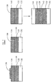
- a suitable substrate 10 e.g. a transparent glass substrate
- a patterned conducting (e.g. ITO) film on an upper surface thereof to provide an electrode.
- a charge transport layer 12 is formed by uniformly coating a material of the desired charge-transport type onto the patterned substrate 10.
- the charge-transport material may be an electron-transport polymer or a hole-transport polymer.
- stage B coloured stripes 14 of low molar mass dyes are deposited on to the exposed surface of the first layer 12 by an ink-jet printing process which utilises the dyes dissolved in a suitable solvent.
- the printed dyes are allowed to diffuse into the first layer 12 for a predetermined period of time to form localised transport recombination/emitter regions 16 within the first layer 12 which extend only partially through the latter.
- excess dye solution is washed away from the surface of the first layer 12 so as to leave the localised regions 16 within the layer 12.
- the exposed upper surface of the first layer 12 is completely smooth and in a condition, after drying as necessary, to receive a second polymer layer 18 of a material of opposite charge transport type to that used for the first layer 12.
- the interface between the first and the second layers 12 and 18 is smooth and planar, and the second layer 18 is of uniform thickness and presents a smooth, planar exposed surface on which patterned electrodes 20 can be deposited in accurate registration with the sites 16 within the first layer 12.
- the provision of the second layer 18 between the transport recombination/emitter regions 16 and the electrodes 20 and the separation of the regions 16 from the ITO substrate 10 reduces the risk of emission quenching in use.
- any lateral diffusion of the dyes in the stripes 14 will lead to a build-up of dye along the longitudinal edges of the localised regions 16.
- the dyes are emissive in dilute solution but not in concentrated solution, this can lead to the formation of concentrated regions along the adjacent longitudinal edges of the regions 16 which are essentially non-emissive and highly absorbing. This reduced the amount of cross-talk between neighbouring pixels.
- the photovoltaic device illustrated therein comprises a pair of glass substrates 30 and 32 between which are disposed charge transport layers 34 and 36.
- the layer 34 constitutes an electron acceptor layer, whilst the layer 36 constitutes a hole acceptor layer.
- Disposed between the substrate 30 and the layer 34 is an aluminium or calcium electrode 38.
- Disposed between the glass substrate 32 and the layer 36 is an ITO or PEDOT (polystyrene sulfonic acid) electrode 40.
- ITO or PEDOT polystyrene sulfonic acid
- the electrode 38 can be formed by thermal evaporation of aluminium or calcium, followed by formation of the layer 34 on top of the resultant structure by spin-coating.
- the layer may be based on a cyano derivative of poly(p)-phenylene vinylene).
- the layer 42 may be formed by applying a dopant such as a porphyrin over the whole of the exposed surface of the layer 34 by dipping the structure into a bath containing a solution of the dopant, and then wiping the structure free of excess dopant so as to prevent diffusion of the dopant completely through the depth of the layer 34.
- the ITO layer 40 may be provided by plasma deposition of ITO on the glass substrate 32, followed by spin-coating of the layer 36 which may, for example, be a phenyl-octyl substituted polythiophene.
- the two sub-structures are laminated together under pressure at elevated temperature in order to secure the exposed surfaces of the layers 34 and 36 together. Further details of a possible way of forming the electrodes 38 and 40 and the layers 34 and 36 are disclosed by M. Granstrom et al in Nature, Vol. 395, 17 th September 1998 page 257.
- the diffused active region 42 enhances photoelectric conversion (i.e. absorption of light followed by charge carrier separation) at the interface between the layers 34 and 36 in use.
- the organic field effect transistor illustrated therein comprises, in sequence, a substrate 50 which may be of glass or a polymeric material (e.g. polyethylene, polycarbonate or polyimide), a gate electrode 52, an insulating layer 54 (e.g. of polymethylmethacrylate), and a semiconductor layer 56.
- Source and drain electrodes 58 and 60 are provided on the exposed surface of the semiconductor layer 56.
- the semiconductor layer 56 may be formed of polythiophene which is locally doped by diffusion of an oxidant, such as 1,4-benzoquinone, in region 62 which is destined to be between the electrodes 58 and 60 in the completed device. Diffusion can be effected in accordance with the present invention by ink-jet printing a localised layer 64 of the oxidant on the surface of the layer 56 in a suitable solvent, followed by heating to promote diffusion, and then removal of excess material. The electrodes 58 and 60 are then formed on top of the thus doped layer 56.
- the contacts between the source and drain electrodes 58 and 60 and the semiconductor layer 56 may be further modified by dye diffusion of dopants into the semiconductor regions directly below the two electrode contacts.
- the oxidant facilitates the formation of positive charges so that it is easier to turn on the FET when a negative DC gate voltage is applied to the gate electrode 52.
- Either of the devices of Figs 2 and 3 may be provided on a flexible polymer substrate. Also, either of these devices may be constructed such that their manufacture does not involve laminating two substrates together.
- the electroluminescent device illustrated therein is produced by providing a substrate 70 on which a metal cathode 72 is formed.
- a layer 74 of electron transport material is formed over the metal cathode 72 and a layer 76 of dye is provided over a region of the exposed upper surface of the layer 74.
- This layer 76 is then caused to diffuse completely into the layer 74 so as to form a diffusion region 78 which extends only partly through the depth of the layer 74.
- a layer 80 of hole transport material is deposited onto the smooth surface of the layer 74 into which the dye 76 has diffused.
- an ITO anode 82 is provided on the layer 80.
- the interface between the layer 80 and the diffused region 78 is smooth and defines an active region in which electron and hole recombination causes light emission in use.
- an ITO-coated substrate 90 is coated with a layer 92 of a PPV polymer or a blend of PPV and PBD (2-(4-biphenylyl)-5-phenyl-1,3,4-oxadiazole).
- a layer 94 of dye to be diffused into the layer 92 is printed onto a region of the upper surface of the latter. After diffusion, the resultant doped zone 96 extends only partly through the thickness of the layer 92. Following this, a PBD layer 98 is deposited over the resultant smooth upper surface of the layer 92, and then a metal cathode 100 is provided on the layer 98 to complete the structure.
- an ITO coated substrate 110 is coated with a PEDOT layer 112, followed by a polyfluorene layer 114.
- a typical repeating unit of a polyfluorene is given below:
- a dopant layer 116 to modify the charge transport properties of the polymer is printed onto the upper surface of the layer 114 and caused to diffuse into the latter to form a doped region 118 which, in this embodiment, extend throughout the thickness of the layer 114, but which may extend only partially through the thickness of the layer 114.
- a metal cathode 120 is provided on top of the layer 114.
- an ITO-coated substrate 130 is covered with a layer 132 of a PPV polymer.
- a layer 134 of a PPV polymer precursor is deposited onto the layer 132.
- a dopant layer 136 is then printed onto a region of the layer 134 and caused to diffuse throughout the precursor polymer layer 134.
- the dopant is chosen so that it interacts with the PPV polymer precursor.
- the PPV polymer precursor may have structure shown below:-
- the above precursor polymer is soluble in, for example, water and methanol, and may be converted to a hydrophobic polymer by heating.
- the hydrophobic polymer is very insoluble in all solvents.
- the dye/dopant used for the layer 136 is hydrophilic, then it preferentially resides in the PPV polymer precursor layer 134 rather than migrating to the layer 132 which is not charged and which is hydrophobic.
- the resultant layer 134 with interacting dopant in region 138 is then cured to form a PPV polymer layer 140 which merges with the underlying PPV polymer layer 132.
- a further polymer layer 142 is provided over the layer 140.
- the layer 142 may likewise be formed of a PPV polymer or it may be a PBD layer or a blend of PPV and PBD.
- a metal cathode 144 is provided over the layer 142 to complete the structure.
- a structure comprising a substrate 150 coated with an ITO anode which in turn is coated with a hole transporting layer 154 including a localised region 156 of a hole-transporting dopant.
- a layer 158 provided on the layer 154 includes a localised emissive dopant region 160 which is spaced from both the upper and lower major surfaces and from the edges of the layer 158.
- the region 160 can be provided within the layer 158 in a similar manner to the way in which the region 138 is provided within the layers 132, 140 and 142 in the embodiment of Fig 7.
- a layer 162 of an electron-transporting material including a localised electron-transporting dopant 164 is a layer 162 of an electron-transporting material including a localised electron-transporting dopant 164.
- the layer 162 is topped by metal cathodes 166.
- One of the cathodes 166 contacts the region 164.
- the region 156 may be formed in the layer 154 in an analogous manner to region 160 in layer 158.
- the layer 154 can be created in two steps. The first involves the formation of, for example, a hydrophilic precursor material layer into which hydrophilic dye/dopant will diffuse easily.
- Conversion of the hydrophilic precursor layer to a hydrophobic material then fixes the dye/ dopant in region 156.
- a second layer of the same precursor material is then deposited and then converted to yield layer 154.
- hydrophilic precursor material described above could be replaced by a hydrophobic precursor material, provided that a hydrophobic dye/dopant is used. Conversion could then yield a hydrophilic material that would trap the dye/dopant in region 156.
- layer 162 incorporating region 164 generation of layer 162 would be carried out in two steps, the second involving a dye/dopant diffusion step.
- ink-jet printing has been described for printing the required dopant/dye pattern on the layer into which it is to be diffused.
- any of the previously described alternative techniques for example bubble-jet printing, screen printing, contact printing, aerosol spraying, electrostatic spraying, electrochemical deposition and photochemical deposition, for applying the dopant to be diffused.
Landscapes
- Engineering & Computer Science (AREA)
- Manufacturing & Machinery (AREA)
- Physics & Mathematics (AREA)
- Optics & Photonics (AREA)
- Electromagnetism (AREA)
- Electroluminescent Light Sources (AREA)
- Thin Film Transistor (AREA)
Applications Claiming Priority (2)
| Application Number | Priority Date | Filing Date | Title |
|---|---|---|---|
| GB9903389 | 1999-02-16 | ||
| GB9903389A GB2347013A (en) | 1999-02-16 | 1999-02-16 | Charge-transport structures |
Publications (2)
| Publication Number | Publication Date |
|---|---|
| EP1030383A2 true EP1030383A2 (fr) | 2000-08-23 |
| EP1030383A3 EP1030383A3 (fr) | 2002-07-17 |
Family
ID=10847778
Family Applications (1)
| Application Number | Title | Priority Date | Filing Date |
|---|---|---|---|
| EP00301196A Withdrawn EP1030383A3 (fr) | 1999-02-16 | 2000-02-16 | Structure à transport de charges |
Country Status (4)
| Country | Link |
|---|---|
| US (1) | US6555840B1 (fr) |
| EP (1) | EP1030383A3 (fr) |
| JP (1) | JP2000243562A (fr) |
| GB (1) | GB2347013A (fr) |
Cited By (10)
| Publication number | Priority date | Publication date | Assignee | Title |
|---|---|---|---|---|
| EP1143773A1 (fr) * | 1999-10-05 | 2001-10-10 | Matsushita Electric Industrial Co., Ltd. | Dispositif electroluminescent et procede de fabrication correspondant, et afficheur et dispositif d'eclairage comprenant ledit dispositif |
| WO2002082561A1 (fr) * | 2001-04-03 | 2002-10-17 | Seiko Epson Corporation | Procede de modelage des contours |
| EP1338431A2 (fr) * | 2002-02-08 | 2003-08-27 | Fuji Photo Film Co., Ltd. | Materiau recepteur d' images avec surface hydrophilique |
| GB2400728A (en) * | 2003-02-26 | 2004-10-20 | Dainippon Printing Co Ltd | Thin film laminate for electrolumninescent element with reduced water content |
| US6982179B2 (en) * | 2002-11-15 | 2006-01-03 | University Display Corporation | Structure and method of fabricating organic devices |
| EP1713136A1 (fr) * | 2005-04-13 | 2006-10-18 | Novaled AG | Dispositif pour diode électroluminescente organique et méthode de sa fabrication |
| EP1836722A2 (fr) * | 2004-12-30 | 2007-09-26 | E.I. Dupont De Nemours And Company | Dispositif electronique comprenant un materiau hote dans une couche et procede de formation dudit dispositif |
| US7531377B2 (en) | 2002-09-03 | 2009-05-12 | Cambridge Display Technology Limited | Optical device |
| US8288187B2 (en) | 2010-01-20 | 2012-10-16 | Universal Display Corporation | Electroluminescent devices for lighting applications |
| US11224284B2 (en) | 2020-02-18 | 2022-01-18 | Colgate-Palmolive Company | Personal care system and fluid supply system thereof |
Families Citing this family (93)
| Publication number | Priority date | Publication date | Assignee | Title |
|---|---|---|---|---|
| US6194167B1 (en) * | 1997-02-18 | 2001-02-27 | Washington State University Research Foundation | ω-3 fatty acid desaturase |
| JP4472056B2 (ja) * | 1999-07-23 | 2010-06-02 | 株式会社半導体エネルギー研究所 | エレクトロルミネッセンス表示装置及びその作製方法 |
| DE10033112C2 (de) * | 2000-07-07 | 2002-11-14 | Siemens Ag | Verfahren zur Herstellung und Strukturierung organischer Feldeffekt-Transistoren (OFET), hiernach gefertigter OFET und seine Verwendung |
| JP2004507096A (ja) * | 2000-08-18 | 2004-03-04 | シーメンス アクチエンゲゼルシヤフト | 有機電界効果トランジスタ(ofet),該有機電界効果トランジスタの製造方法、前記有機電界効果トランジスタから形成される集積回路、及び該集積回路の使用 |
| US7875975B2 (en) * | 2000-08-18 | 2011-01-25 | Polyic Gmbh & Co. Kg | Organic integrated circuit completely encapsulated by multi-layered barrier and included in RFID tag |
| DE10043204A1 (de) * | 2000-09-01 | 2002-04-04 | Siemens Ag | Organischer Feld-Effekt-Transistor, Verfahren zur Strukturierung eines OFETs und integrierte Schaltung |
| DE10044842A1 (de) * | 2000-09-11 | 2002-04-04 | Siemens Ag | Organischer Gleichrichter, Schaltung, RFID-Tag und Verwendung eines organischen Gleichrichters |
| DE10045192A1 (de) * | 2000-09-13 | 2002-04-04 | Siemens Ag | Organischer Datenspeicher, RFID-Tag mit organischem Datenspeicher, Verwendung eines organischen Datenspeichers |
| US20040026121A1 (en) * | 2000-09-22 | 2004-02-12 | Adolf Bernds | Electrode and/or conductor track for organic components and production method thereof |
| JP2002215065A (ja) * | 2000-11-02 | 2002-07-31 | Seiko Epson Corp | 有機エレクトロルミネッセンス装置及びその製造方法、並びに電子機器 |
| DE10061299A1 (de) | 2000-12-08 | 2002-06-27 | Siemens Ag | Vorrichtung zur Feststellung und/oder Weiterleitung zumindest eines Umwelteinflusses, Herstellungsverfahren und Verwendung dazu |
| DE10061297C2 (de) * | 2000-12-08 | 2003-05-28 | Siemens Ag | Verfahren zur Sturkturierung eines OFETs |
| DE10063721A1 (de) * | 2000-12-20 | 2002-07-11 | Merck Patent Gmbh | Organischer Halbleiter, Herstellungsverfahren dazu und Verwendungen |
| DE10105914C1 (de) | 2001-02-09 | 2002-10-10 | Siemens Ag | Organischer Feldeffekt-Transistor mit fotostrukturiertem Gate-Dielektrikum und ein Verfahren zu dessen Erzeugung |
| EP1374138A2 (fr) * | 2001-03-26 | 2004-01-02 | Siemens Aktiengesellschaft | Appareil comprenant au moins deux composants electroniques organiques et son procede de production |
| DE10116876B4 (de) * | 2001-04-04 | 2004-09-23 | Infineon Technologies Ag | Verfahren zur Dotierung elektrisch leitfähiger organischer Verbindungen, organischer Feldeffekttransistor sowie Verfahren zu dessen Herstellung |
| DE10126860C2 (de) * | 2001-06-01 | 2003-05-28 | Siemens Ag | Organischer Feldeffekt-Transistor, Verfahren zu seiner Herstellung und Verwendung zum Aufbau integrierter Schaltungen |
| JP4648594B2 (ja) * | 2001-09-07 | 2011-03-09 | ブラザー工業株式会社 | 表示装置の製造方法 |
| EP1425170B1 (fr) * | 2001-09-11 | 2006-01-25 | Dupont Teijin Films U.S. Limited Partnership | Film de poly(ethylene naphtalate) thermostabilise pour dispositifs electroniques et opto-electroniques souples |
| DE10151036A1 (de) * | 2001-10-16 | 2003-05-08 | Siemens Ag | Isolator für ein organisches Elektronikbauteil |
| DE10151440C1 (de) * | 2001-10-18 | 2003-02-06 | Siemens Ag | Organisches Elektronikbauteil, Verfahren zu seiner Herstellung und seine Verwendung |
| US7042024B2 (en) * | 2001-11-09 | 2006-05-09 | Semiconductor Energy Laboratory Co., Ltd. | Light emitting apparatus and method for manufacturing the same |
| CN100380673C (zh) * | 2001-11-09 | 2008-04-09 | 株式会社半导体能源研究所 | 发光设备及其制造方法 |
| DE10160732A1 (de) * | 2001-12-11 | 2003-06-26 | Siemens Ag | Organischer Feld-Effekt-Transistor mit verschobener Schwellwertspannung und Verwendung dazu |
| DE10212640B4 (de) * | 2002-03-21 | 2004-02-05 | Siemens Ag | Logische Bauteile aus organischen Feldeffekttransistoren |
| DE10212639A1 (de) * | 2002-03-21 | 2003-10-16 | Siemens Ag | Vorrichtung und Verfahren zur Laserstrukturierung von Funktionspolymeren und Verwendungen |
| KR100437533B1 (ko) * | 2002-05-29 | 2004-06-30 | 엘지.필립스 엘시디 주식회사 | 액티브 매트릭스형 유기전계발광 소자 및 그의 제조방법 |
| DE10226370B4 (de) * | 2002-06-13 | 2008-12-11 | Polyic Gmbh & Co. Kg | Substrat für ein elektronisches Bauteil, Verwendung des Substrates, Verfahren zur Erhöhung der Ladungsträgermobilität und Organischer Feld-Effekt Transistor (OFET) |
| US8044517B2 (en) | 2002-07-29 | 2011-10-25 | Polyic Gmbh & Co. Kg | Electronic component comprising predominantly organic functional materials and a method for the production thereof |
| ATE395955T1 (de) * | 2002-08-08 | 2008-06-15 | Polyic Gmbh & Co Kg | Elektronisches gerät |
| US7414513B2 (en) | 2002-08-23 | 2008-08-19 | Polyic Gmbh & Co. Kg | Organic component for overvoltage protection and associated circuit |
| US20040124421A1 (en) * | 2002-09-20 | 2004-07-01 | Semiconductor Energy Laboratory Co., Ltd. | Light-emitting device and manufacturing method thereof |
| WO2004042837A2 (fr) * | 2002-11-05 | 2004-05-21 | Siemens Aktiengesellschaft | Composant electronique organique a structuration haute resolution et procede de production de ce composant |
| DE10253154A1 (de) * | 2002-11-14 | 2004-05-27 | Siemens Ag | Messgerät zur Bestimmung eines Analyten in einer Flüssigkeitsprobe |
| US20040096570A1 (en) * | 2002-11-15 | 2004-05-20 | Michael Weaver | Structure and method of fabricating organic devices |
| WO2004047194A2 (fr) * | 2002-11-19 | 2004-06-03 | Polyic Gmbh & Co.Kg | Composant electronique organique comportant le meme materiau organique pour au moins deux couches fonctionnelles |
| CN1574214A (zh) * | 2003-06-03 | 2005-02-02 | 国际商业机器公司 | 用于制造电子器件的基于熔化的图案化工艺 |
| DE10338277A1 (de) * | 2003-08-20 | 2005-03-17 | Siemens Ag | Organischer Kondensator mit spannungsgesteuerter Kapazität |
| GB0319799D0 (en) * | 2003-08-22 | 2003-09-24 | Itm Power Ltd | Photovoltaic cell |
| DE10339036A1 (de) | 2003-08-25 | 2005-03-31 | Siemens Ag | Organisches elektronisches Bauteil mit hochaufgelöster Strukturierung und Herstellungsverfahren dazu |
| DE10340644B4 (de) * | 2003-09-03 | 2010-10-07 | Polyic Gmbh & Co. Kg | Mechanische Steuerelemente für organische Polymerelektronik |
| DE10340643B4 (de) * | 2003-09-03 | 2009-04-16 | Polyic Gmbh & Co. Kg | Druckverfahren zur Herstellung einer Doppelschicht für Polymerelektronik-Schaltungen, sowie dadurch hergestelltes elektronisches Bauelement mit Doppelschicht |
| US7655961B2 (en) * | 2003-10-02 | 2010-02-02 | Maxdem Incorporated | Organic diodes and materials |
| JP4285741B2 (ja) * | 2003-10-24 | 2009-06-24 | 独立行政法人産業技術総合研究所 | 有機電界発光素子およびその作製方法 |
| JP2007511885A (ja) * | 2003-11-10 | 2007-05-10 | イー・アイ・デュポン・ドウ・ヌムール・アンド・カンパニー | ゲスト材料を含む領域を有する有機層を形成する方法、およびそれを組入れる有機電子デバイス |
| US20050100657A1 (en) * | 2003-11-10 | 2005-05-12 | Macpherson Charles D. | Organic material with a region including a guest material and organic electronic devices incorporating the same |
| DE102004002024A1 (de) * | 2004-01-14 | 2005-08-11 | Siemens Ag | Organischer Transistor mit selbstjustierender Gate-Elektrode und Verfahren zu dessen Herstellung |
| CN100363458C (zh) * | 2004-03-29 | 2008-01-23 | 中国科学院长春应用化学研究所 | 白色电致发光高分子材料及其制备方法 |
| US7540978B2 (en) | 2004-08-05 | 2009-06-02 | Novaled Ag | Use of an organic matrix material for producing an organic semiconductor material, organic semiconductor material and electronic component |
| US8653537B2 (en) | 2004-08-13 | 2014-02-18 | Novaled Ag | Layer assembly for a light-emitting component |
| DE102004040831A1 (de) * | 2004-08-23 | 2006-03-09 | Polyic Gmbh & Co. Kg | Funketikettfähige Umverpackung |
| DE602004006275T2 (de) | 2004-10-07 | 2007-12-20 | Novaled Ag | Verfahren zur Dotierung von einem Halbleitermaterial mit Cäsium |
| DE102004059464A1 (de) * | 2004-12-10 | 2006-06-29 | Polyic Gmbh & Co. Kg | Elektronikbauteil mit Modulator |
| DE102004059465A1 (de) * | 2004-12-10 | 2006-06-14 | Polyic Gmbh & Co. Kg | Erkennungssystem |
| DE102004059467A1 (de) * | 2004-12-10 | 2006-07-20 | Polyic Gmbh & Co. Kg | Gatter aus organischen Feldeffekttransistoren |
| DE102004063435A1 (de) | 2004-12-23 | 2006-07-27 | Polyic Gmbh & Co. Kg | Organischer Gleichrichter |
| DE102005009819A1 (de) | 2005-03-01 | 2006-09-07 | Polyic Gmbh & Co. Kg | Elektronikbaugruppe |
| DE102005009820A1 (de) * | 2005-03-01 | 2006-09-07 | Polyic Gmbh & Co. Kg | Elektronikbaugruppe mit organischen Logik-Schaltelementen |
| DE502005002342D1 (de) * | 2005-03-15 | 2008-02-07 | Novaled Ag | Lichtemittierendes Bauelement |
| TWI254594B (en) * | 2005-03-17 | 2006-05-01 | Ind Tech Res Inst | Color organic light-emitting display and manufacturing process thereof |
| JP4667096B2 (ja) * | 2005-03-25 | 2011-04-06 | 株式会社半導体エネルギー研究所 | 有機半導体装置及びその作製方法 |
| TWI305431B (en) * | 2005-04-06 | 2009-01-11 | Au Optronics Corp | Organic light emitting diode display |
| DE102005017655B4 (de) * | 2005-04-15 | 2008-12-11 | Polyic Gmbh & Co. Kg | Mehrschichtiger Verbundkörper mit elektronischer Funktion |
| DE502005009415D1 (de) * | 2005-05-27 | 2010-05-27 | Novaled Ag | Transparente organische Leuchtdiode |
| EP2045843B1 (fr) * | 2005-06-01 | 2012-08-01 | Novaled AG | Composant émettant de la lumière à l'aide d'un agencement d'électrodes |
| EP1739765A1 (fr) * | 2005-07-01 | 2007-01-03 | Novaled AG | Diode organoluminescent et empilement des OLEDs |
| DE102005031448A1 (de) | 2005-07-04 | 2007-01-11 | Polyic Gmbh & Co. Kg | Aktivierbare optische Schicht |
| DE102005035589A1 (de) | 2005-07-29 | 2007-02-01 | Polyic Gmbh & Co. Kg | Verfahren zur Herstellung eines elektronischen Bauelements |
| DE102005035590A1 (de) * | 2005-07-29 | 2007-02-01 | Polyic Gmbh & Co. Kg | Elektronisches Bauelement |
| KR100721948B1 (ko) * | 2005-08-30 | 2007-05-25 | 삼성에스디아이 주식회사 | 유기 전계 발광 표시 장치 및 그의 제조 방법 |
| DE102005044306A1 (de) * | 2005-09-16 | 2007-03-22 | Polyic Gmbh & Co. Kg | Elektronische Schaltung und Verfahren zur Herstellung einer solchen |
| WO2007055186A1 (fr) | 2005-11-09 | 2007-05-18 | Konica Minolta Holdings, Inc. | Dispositif électroluminescent organique, affichage et dispositif d'éclairage |
| DE502005004675D1 (de) * | 2005-12-21 | 2008-08-21 | Novaled Ag | Organisches Bauelement |
| DE602006001930D1 (de) * | 2005-12-23 | 2008-09-04 | Novaled Ag | tur von organischen Schichten |
| EP1804308B1 (fr) * | 2005-12-23 | 2012-04-04 | Novaled AG | Dispositif organique émetteur de lumière ayant plusieurs unités électroluminescentes organiques empilées les unes sur les autres |
| KR101181820B1 (ko) | 2005-12-29 | 2012-09-11 | 삼성에스디아이 주식회사 | 태양 전지의 제조 방법 |
| EP1808909A1 (fr) | 2006-01-11 | 2007-07-18 | Novaled AG | Dispositif électroluminescent |
| US20070176539A1 (en) * | 2006-02-01 | 2007-08-02 | Osram Opto Semiconductors Gmbh | OLED with area defined multicolor emission within a single lighting element |
| EP1848049B1 (fr) * | 2006-04-19 | 2009-12-09 | Novaled AG | Dispositif d'émission de lumière |
| KR100918362B1 (ko) * | 2006-07-27 | 2009-09-22 | 주식회사 엘지화학 | 유기 박막 트랜지스터 및 이의 제조방법 |
| DE102006059509B4 (de) * | 2006-12-14 | 2012-05-03 | Novaled Ag | Organisches Leuchtbauelement |
| US7649220B2 (en) * | 2007-03-29 | 2010-01-19 | Avago Technologies Ecbu Ip (Singapore) Pte. Ltd. | Photodetector having dark current correction |
| DE102007019260B4 (de) * | 2007-04-17 | 2020-01-16 | Novaled Gmbh | Nichtflüchtiges organisches Speicherelement |
| DE102008036062B4 (de) * | 2008-08-04 | 2015-11-12 | Novaled Ag | Organischer Feldeffekt-Transistor |
| DE102008036063B4 (de) * | 2008-08-04 | 2017-08-31 | Novaled Gmbh | Organischer Feldeffekt-Transistor |
| DE102009013685B4 (de) * | 2009-03-20 | 2013-01-31 | Novaled Ag | Verwendung einer organischen Diode als organische Zenerdiode und Verfahren zum Betreiben |
| CN102148429B (zh) * | 2010-02-06 | 2016-03-30 | 清华大学 | 纳米光学天线阵列的制造方法 |
| WO2012011511A1 (fr) * | 2010-07-21 | 2012-01-26 | 住友化学株式会社 | Procédé de fabrication d'élément électroluminescent organique |
| CN103733346A (zh) * | 2011-08-22 | 2014-04-16 | 住友化学株式会社 | 有机薄膜晶体管 |
| JP2013211534A (ja) * | 2012-02-28 | 2013-10-10 | Sumitomo Chemical Co Ltd | 有機薄膜トランジスタの製造方法及び有機薄膜トランジスタ |
| JP2014179419A (ja) * | 2013-03-14 | 2014-09-25 | Alpha- Design Kk | 電子部品の接合方法 |
| EP3254315A1 (fr) * | 2015-02-04 | 2017-12-13 | Basf Se | Transistors à effet de champ organiques à faible résistance de contact |
| JP6943400B2 (ja) * | 2017-09-08 | 2021-09-29 | 株式会社アロマビット | 導電性高分子膜の作製方法 |
Citations (1)
| Publication number | Priority date | Publication date | Assignee | Title |
|---|---|---|---|---|
| EP0892028A2 (fr) * | 1997-07-16 | 1999-01-20 | Seiko Epson Corporation | Composition pour un élément électroluminescent organique et procédé de fabrication d'un élément électroluminescent organique |
Family Cites Families (14)
| Publication number | Priority date | Publication date | Assignee | Title |
|---|---|---|---|---|
| CA2085445A1 (fr) * | 1991-12-30 | 1993-07-01 | Jon E. Littman | Dispositif electroluminescent organique a construction simple ayant un rendement eleve |
| JPH06116552A (ja) * | 1992-10-02 | 1994-04-26 | Sekisui Chem Co Ltd | 有機電界発光素子 |
| US5405709A (en) * | 1993-09-13 | 1995-04-11 | Eastman Kodak Company | White light emitting internal junction organic electroluminescent device |
| JP3463362B2 (ja) * | 1993-12-28 | 2003-11-05 | カシオ計算機株式会社 | 電界発光素子の製造方法および電界発光素子 |
| JP3249297B2 (ja) * | 1994-07-14 | 2002-01-21 | 三洋電機株式会社 | 有機電界発光素子 |
| WO1996031909A1 (fr) * | 1995-04-05 | 1996-10-10 | Uniax Corporation | Processeur d'images intelligent en polymere |
| EP1347518A3 (fr) * | 1995-11-28 | 2005-11-09 | International Business Machines Corporation | Alliages organiques/non-organiques utilisés pour améliorer des dispositifs électroluminescents organiques |
| US6117529A (en) * | 1996-12-18 | 2000-09-12 | Gunther Leising | Organic electroluminescence devices and displays |
| US6075317A (en) * | 1998-07-30 | 2000-06-13 | Alliedsignal Inc. | Electroluminescent device having increased brightness and resolution and method of fabrication |
| US6048573A (en) * | 1998-11-13 | 2000-04-11 | Eastman Kodak Company | Method of making an organic light-emitting device |
| JP2000196140A (ja) * | 1998-12-28 | 2000-07-14 | Sharp Corp | 有機エレクトロルミネッセンス素子とその製造法 |
| JP3885412B2 (ja) * | 1999-05-25 | 2007-02-21 | 松下電器産業株式会社 | 有機電界発光素子 |
| US6278236B1 (en) * | 1999-09-02 | 2001-08-21 | Eastman Kodak Company | Organic electroluminescent devices with electron-injecting layer having aluminum and alkali halide |
| US6214151B1 (en) * | 1999-11-05 | 2001-04-10 | International Business Machines Corporation | Thermal dye transfer process for preparing opto-electronic devices |
-
1999
- 1999-02-16 GB GB9903389A patent/GB2347013A/en not_active Withdrawn
-
2000
- 2000-02-15 US US09/504,557 patent/US6555840B1/en not_active Expired - Fee Related
- 2000-02-16 JP JP2000038886A patent/JP2000243562A/ja not_active Withdrawn
- 2000-02-16 EP EP00301196A patent/EP1030383A3/fr not_active Withdrawn
Patent Citations (1)
| Publication number | Priority date | Publication date | Assignee | Title |
|---|---|---|---|---|
| EP0892028A2 (fr) * | 1997-07-16 | 1999-01-20 | Seiko Epson Corporation | Composition pour un élément électroluminescent organique et procédé de fabrication d'un élément électroluminescent organique |
Non-Patent Citations (4)
| Title |
|---|
| FUJII A ET AL: "ORGANIC PHOTOVOLTAIC CELL WITH DONOR-ACCEPTOR DOUBLE HETEROJUNCTIONS" JAPANESE JOURNAL OF APPLIED PHYSICS, PUBLICATION OFFICE JAPANESE JOURNAL OF APPLIED PHYSICS. TOKYO, JP, vol. 35, no. 11A, 1 November 1996 (1996-11-01), pages L1438-L1441, XP000727737 ISSN: 0021-4922 * |
| GRANSTROEM M ET AL: "LAMINATED FABRICATION OF POLYMERIC PHOTOVOLTAIC DIODES" NATURE, MACMILLAN JOURNALS LTD. LONDON, GB, vol. 395, 17 September 1998 (1998-09-17), pages 257-260, XP000931238 ISSN: 0028-0836 * |
| PICHLER K ET AL: "FIELD-EFFECT TRANSISTORS BASED ON POLY(P-PHENYLENE VINYLENE) DOPED BY ION IMPLANTATION" JOURNAL OF APPLIED PHYSICS, AMERICAN INSTITUTE OF PHYSICS. NEW YORK, US, vol. 77, no. 7, 1 April 1995 (1995-04-01), pages 3523-3527, XP000501594 ISSN: 0021-8979 * |
| SHOUSTIKOV A A ET AL: "ELECTROLUMINESCENCE COLOR TUNING BY DYE DOPING IN ORGANIC LIGHT-EMITTING DIODES" IEEE JOURNAL OF SELECTED TOPICS IN QUANTUM ELECTRONICS, IEEE SERVICE CENTER, US, vol. 4, no. 1, 1998, pages 3-13, XP000766104 ISSN: 1077-260X * |
Cited By (23)
| Publication number | Priority date | Publication date | Assignee | Title |
|---|---|---|---|---|
| EP1143773A1 (fr) * | 1999-10-05 | 2001-10-10 | Matsushita Electric Industrial Co., Ltd. | Dispositif electroluminescent et procede de fabrication correspondant, et afficheur et dispositif d'eclairage comprenant ledit dispositif |
| EP1143773A4 (fr) * | 1999-10-05 | 2007-02-21 | Matsushita Electric Ind Co Ltd | Dispositif electroluminescent et procede de fabrication correspondant, et afficheur et dispositif d'eclairage comprenant ledit dispositif |
| WO2002082561A1 (fr) * | 2001-04-03 | 2002-10-17 | Seiko Epson Corporation | Procede de modelage des contours |
| US7560133B2 (en) | 2001-04-03 | 2009-07-14 | Seiko Epson Corporation | Patterning method |
| CN1331246C (zh) * | 2001-04-03 | 2007-08-08 | 精工爱普生株式会社 | 构图方法 |
| US6878470B2 (en) | 2002-02-08 | 2005-04-12 | Fuji Photo Film Co., Ltd. | Visible image receiving material, conductive pattern material and organic electroluminescence element, using member having surface hydrophilicity |
| EP1338431A2 (fr) * | 2002-02-08 | 2003-08-27 | Fuji Photo Film Co., Ltd. | Materiau recepteur d' images avec surface hydrophilique |
| EP1338431A3 (fr) * | 2002-02-08 | 2003-10-01 | Fuji Photo Film Co., Ltd. | Materiau recepteur d' images avec surface hydrophilique |
| US7531377B2 (en) | 2002-09-03 | 2009-05-12 | Cambridge Display Technology Limited | Optical device |
| US7989255B2 (en) | 2002-09-03 | 2011-08-02 | Cambridge Display Technology Limited | Optical device |
| US6982179B2 (en) * | 2002-11-15 | 2006-01-03 | University Display Corporation | Structure and method of fabricating organic devices |
| US7488540B2 (en) | 2003-02-26 | 2009-02-10 | Dai Nippon Printing Co., Ltd. | Thin film laminate and luminescent element |
| GB2400728B (en) * | 2003-02-26 | 2006-06-21 | Dainippon Printing Co Ltd | Thin film laminate and luminescent element |
| GB2400728A (en) * | 2003-02-26 | 2004-10-20 | Dainippon Printing Co Ltd | Thin film laminate for electrolumninescent element with reduced water content |
| EP1836722A2 (fr) * | 2004-12-30 | 2007-09-26 | E.I. Dupont De Nemours And Company | Dispositif electronique comprenant un materiau hote dans une couche et procede de formation dudit dispositif |
| EP1836722A4 (fr) * | 2004-12-30 | 2010-09-29 | Du Pont | Dispositif electronique comprenant un materiau hote dans une couche et procede de formation dudit dispositif |
| TWI381566B (zh) * | 2004-12-30 | 2013-01-01 | Du Pont | 其中一層含有客體材料之電子裝置及形成該電子裝置之方法 |
| EP1713136A1 (fr) * | 2005-04-13 | 2006-10-18 | Novaled AG | Dispositif pour diode électroluminescente organique et méthode de sa fabrication |
| US7911129B2 (en) | 2005-04-13 | 2011-03-22 | Novaled Ag | Arrangement for an organic pin-type light-emitting diode and method for manufacturing |
| US8288187B2 (en) | 2010-01-20 | 2012-10-16 | Universal Display Corporation | Electroluminescent devices for lighting applications |
| US9054344B2 (en) | 2010-01-20 | 2015-06-09 | Universal Display Corporation | Electroluminescent devices for lighting applications |
| US11224284B2 (en) | 2020-02-18 | 2022-01-18 | Colgate-Palmolive Company | Personal care system and fluid supply system thereof |
| US11730259B2 (en) | 2020-02-18 | 2023-08-22 | Colgate-Palmolive Company | Personal care system and fluid supply system thereof |
Also Published As
| Publication number | Publication date |
|---|---|
| GB9903389D0 (en) | 1999-04-07 |
| JP2000243562A (ja) | 2000-09-08 |
| US6555840B1 (en) | 2003-04-29 |
| GB2347013A (en) | 2000-08-23 |
| EP1030383A3 (fr) | 2002-07-17 |
Similar Documents
| Publication | Publication Date | Title |
|---|---|---|
| US6555840B1 (en) | Charge-transport structures | |
| EP1518281B8 (fr) | Couches tampons pour dispositifs electroluminescents organiques et procédés de fabrication et utilisation | |
| Forrest | Active optoelectronics using thin-film organic semiconductors | |
| US7629061B2 (en) | Heterostructure devices using cross-linkable polymers | |
| US9054317B2 (en) | Multilayer organic device | |
| TWI355862B (en) | Methods for producing full-color organic electrolu | |
| US6784016B2 (en) | Organic light-emitting devices with blocking and transport layers | |
| US6372154B1 (en) | Luminescent ink for printing of organic luminescent devices | |
| EP1816690B1 (fr) | Affichage électroluminescent organique (DELO) avec émission multicolore définie au sein d'un seul élément lumineux | |
| KR101366655B1 (ko) | 유기 전자 장치들의 처리 및 성능을 개선하기 위한중성화된 애노드 버퍼층들 | |
| DE10344224A1 (de) | Die Wirkungen von defekten in organischen elektronischen Vorrichtungen mildernde Elektroden | |
| US7407716B2 (en) | Light emitting devices with multiple light emitting layers to achieve broad spectrum | |
| JP2007027763A (ja) | 積み重ねられた複数の層を有する有機発光ダイオードデバイスおよび有機発光ダイオードデバイス | |
| CN102132441A (zh) | 制造显示器的方法 | |
| US7452613B2 (en) | White organic electroluminescent device | |
| US20050156176A1 (en) | Method for printing organic devices | |
| US20050276910A1 (en) | Post processing of films to improve film quality | |
| US6756249B2 (en) | Method of manufacturing organic electroluminescent device | |
| CN1926698B (zh) | 导电聚合物的沉积 | |
| CN112266656A (zh) | 一种用于喷墨打印的可原位交联空穴传输材料墨水配方及其在电致发光器件中的应用 | |
| CN101087012B (zh) | 有机电激发光组件 | |
| GB2460216A (en) | Hole transport material composition | |
| Xie | Solution-Processed Organic Light-Emitting Devices |
Legal Events
| Date | Code | Title | Description |
|---|---|---|---|
| PUAI | Public reference made under article 153(3) epc to a published international application that has entered the european phase |
Free format text: ORIGINAL CODE: 0009012 |
|
| AK | Designated contracting states |
Kind code of ref document: A2 Designated state(s): AT BE CH CY DE DK ES FI FR GB GR IE IT LI LU MC NL PT SE |
|
| AX | Request for extension of the european patent |
Free format text: AL;LT;LV;MK;RO;SI |
|
| PUAL | Search report despatched |
Free format text: ORIGINAL CODE: 0009013 |
|
| AK | Designated contracting states |
Kind code of ref document: A3 Designated state(s): AT BE CH CY DE DK ES FI FR GB GR IE IT LI LU MC NL PT SE |
|
| AX | Request for extension of the european patent |
Free format text: AL;LT;LV;MK;RO;SI |
|
| 17P | Request for examination filed |
Effective date: 20021119 |
|
| AKX | Designation fees paid |
Designated state(s): DE FR GB |
|
| 17Q | First examination report despatched |
Effective date: 20060727 |
|
| STAA | Information on the status of an ep patent application or granted ep patent |
Free format text: STATUS: THE APPLICATION IS DEEMED TO BE WITHDRAWN |
|
| 18D | Application deemed to be withdrawn |
Effective date: 20061207 |