EP1030118A1 - Emaillierter Einschub - Google Patents
Emaillierter Einschub Download PDFInfo
- Publication number
- EP1030118A1 EP1030118A1 EP00101705A EP00101705A EP1030118A1 EP 1030118 A1 EP1030118 A1 EP 1030118A1 EP 00101705 A EP00101705 A EP 00101705A EP 00101705 A EP00101705 A EP 00101705A EP 1030118 A1 EP1030118 A1 EP 1030118A1
- Authority
- EP
- European Patent Office
- Prior art keywords
- insert
- area
- enamelled
- slide bracket
- tray
- Prior art date
- Legal status (The legal status is an assumption and is not a legal conclusion. Google has not performed a legal analysis and makes no representation as to the accuracy of the status listed.)
- Granted
Links
Images
Classifications
-
- F—MECHANICAL ENGINEERING; LIGHTING; HEATING; WEAPONS; BLASTING
- F24—HEATING; RANGES; VENTILATING
- F24C—DOMESTIC STOVES OR RANGES ; DETAILS OF DOMESTIC STOVES OR RANGES, OF GENERAL APPLICATION
- F24C15/00—Details
- F24C15/16—Shelves, racks or trays inside ovens; Supports therefor
Definitions
- the present invention relates to an enamelled insert, such as. B. baking tray, in particular for an oven with enamelled guideways in the area of the oven muffle side walls, with two opposite side support areas of the Inserts, each of which has a side edge area rolled downwards, on which a metallic sliding support of the insert is held.
- Such an insert is known from DE 35 44 582 C2, the one on the side Baking trays pulled out sliding and support area pulled down and to is cranked inside. This area is surrounded by a metal profile. The The manufacture and assembly of such a metal profile is complex.
- the object of the present invention is to construct an enamelled insert to simplify according to the preamble of claim 1.
- this is achieved with a generic insert in that in a sliding bracket is held clamped to the edge region and consists of at least two notches of the rolled edge area raised as a sliding support of the insert protrudes.
- the complex manufacture and assembly of the profile part according to the state of the art can be omitted according to the invention when using the slide bracket.
- each of the two side support areas is precise one slide bracket is provided, i.e. two slide brackets per slot.
- the notch is in the corner area of the insert, the notch being adjacent in both Long sides of the insert extends.
- a trough-shaped enamelled baking sheet 1 with a bottom 3 and four side walls 5 is in not shown, known enameled guideways in the Insertable area of the oven muffle side walls of an oven.
- the baking sheet 1 each has one of the Sidewall 5 bent at right angles and extending substantially horizontally Support area 7 in this area 7 are over the entire depth of the baking sheet 1 air passage openings 9 are provided in order to be known Recirculation mode of the oven ensures good warm air distribution in the oven muffle despite being pushed in To enable baking tray 1.
- the air passage openings 9 can however, it can also be provided in the front and rear area of the baking sheet 1, and, if necessary, be designed to be considerably narrower or even be omitted entirely.
- the lateral end section of the support area 7 of the baking sheet 1 is over the entire depth of which is designed as a rolled-up edge region 11.
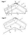
- the corner area of the baking sheet 1 is in the essentially L-shaped extending notch 15 is provided, which both in extends the edge region 11 as well as in the front region 13. This notch 15 is designed accordingly in all four corner areas of the baking sheet 1.
- the slide bracket 17 has in its two corner areas each a hump-shaped and essentially L-shaped accordingly the notch 15 extending elevation 19.
- the sliding bracket according to the embodiment also be formed from two individual parts. The four part slide bars are then can be clipped into the corner areas of the baking sheet to be retrofitted.
- the sliding bracket according to the embodiment also be formed from two individual parts. The four part slide bars are then can be clipped into the corner areas of the baking sheet to be retrofitted.
Landscapes
- Engineering & Computer Science (AREA)
- Chemical & Material Sciences (AREA)
- Combustion & Propulsion (AREA)
- Mechanical Engineering (AREA)
- General Engineering & Computer Science (AREA)
- Baking, Grill, Roasting (AREA)
- Fishing Rods (AREA)
- Seal Device For Vehicle (AREA)
- Table Equipment (AREA)
- Vehicle Step Arrangements And Article Storage (AREA)
Abstract
Description
- Fig. 1
- ausschnittsweise in einer perspektivischen Ansicht von unten den Einschub mit montiertem Gleitbügel und
- Fig. 2
- in der gleichen Ansicht den Einschub mit demontiertem Gleitbügel.
Claims (5)
- Emaillierter Einschub, wie z. B. Backblech, insbesondere für einen Backofen mit emaillierten Führungsbahnen im Bereich der Ofenmuffelseitenwandungen, mit zwei gegenüberliegenden seitlichen Auflagebereichen des Einschubes, die jeweils einen nach unten eingerollten seitlichen Randbereich aufweisen, an dem eine metallische Gleitauflage des Einschubes gehaltert ist, dadurch gekennzeichnet, daß in dem Randbereich (11) ein Gleitbügel (17) geklemmt gehaltert ist, der aus zumindest zwei Ausklinkungen (15) des eingerollten Randbereiches erhaben als Gleitauflage (19) des Einschubes (1) ragt.
- Einschub nach Anspruch 1, dadurch gekennzeichnet, daß der Gleitbügel (17) deckseitig durch den Randbereich (11) des Einschubes (1) abgedeckt ist.
- Einschub nach Anspruch 1 oder 2, dadurch gekennzeichnet, daß in jedem der beiden seitlichen Auflagebereiche (7) genau ein Gleitbügel (17) vorgesehen ist.
- Einschub nach einem der vorhergehenden Ansprüche, dadurch gekennzeichnet, daß im dem Randbereich (11) des Einschubes (1) genau zwei Ausklinkungen (15) ausgebildet sind, die möglichst weit voneinander beabstandet sind.
- Einschub nach einem der vorhergehenden Ansprüche, dadurch gekennzeichnet, daß die Ausklinkung (15) im Eckbereich des Einschubes (1) ausgebildet ist und sich in beide benachbarten Längsseiten des Einschubes (1) erstreckt.
Applications Claiming Priority (2)
| Application Number | Priority Date | Filing Date | Title |
|---|---|---|---|
| DE19906364A DE19906364A1 (de) | 1999-02-16 | 1999-02-16 | Emaillierter Einschub |
| DE19906364 | 1999-02-16 |
Publications (2)
| Publication Number | Publication Date |
|---|---|
| EP1030118A1 true EP1030118A1 (de) | 2000-08-23 |
| EP1030118B1 EP1030118B1 (de) | 2004-06-30 |
Family
ID=7897614
Family Applications (1)
| Application Number | Title | Priority Date | Filing Date |
|---|---|---|---|
| EP00101705A Expired - Lifetime EP1030118B1 (de) | 1999-02-16 | 2000-01-27 | Emaillierter Einschub |
Country Status (4)
| Country | Link |
|---|---|
| US (1) | US6318582B1 (de) |
| EP (1) | EP1030118B1 (de) |
| AT (1) | ATE270418T1 (de) |
| DE (2) | DE19906364A1 (de) |
Cited By (1)
| Publication number | Priority date | Publication date | Assignee | Title |
|---|---|---|---|---|
| EP1625816A1 (de) * | 2004-08-13 | 2006-02-15 | Electrolux Home Products Corporation N.V. | Koch-, Brat- oder Backgerät, insbesondere Backblech |
Families Citing this family (1)
| Publication number | Priority date | Publication date | Assignee | Title |
|---|---|---|---|---|
| EP1966542B1 (de) * | 2005-12-30 | 2012-01-18 | Arçelik Anonim Sirketi | Ofen |
Citations (4)
| Publication number | Priority date | Publication date | Assignee | Title |
|---|---|---|---|---|
| US2040996A (en) * | 1934-03-07 | 1936-05-19 | Warren H Hungerford | Baking pan |
| FR1041050A (fr) * | 1951-08-02 | 1953-10-20 | J B Barbera & Cie | Perfectionnement aux plateaux à cuire le pain |
| DE3544582A1 (de) | 1985-12-17 | 1987-06-25 | Bosch Siemens Hausgeraete | Anordnung fuer emaillierte einschuebe in backoefen |
| DE29804533U1 (de) * | 1998-03-13 | 1998-05-20 | S & R Maschinenbau GmbH, 35315 Homberg | Backofenrost oder Backblech |
Family Cites Families (10)
| Publication number | Priority date | Publication date | Assignee | Title |
|---|---|---|---|---|
| US1303465A (en) * | 1919-05-13 | Marcy j | ||
| BE532137A (de) * | ||||
| US769271A (en) * | 1904-03-09 | 1904-09-06 | Emanuel E Norquist | Metal tank. |
| US1807394A (en) * | 1927-07-30 | 1931-05-26 | Arthur L Dunham | Interiorly enameled boiler |
| US2216147A (en) * | 1939-02-01 | 1940-10-01 | Ashley F Ward | Aluminum baking pan |
| US2474102A (en) * | 1945-10-08 | 1949-06-21 | Gershon Benjamin | Stove mat |
| US2628739A (en) * | 1946-06-07 | 1953-02-17 | Vischer Alfred Jun | Container closure |
| US3622037A (en) * | 1969-07-17 | 1971-11-23 | Rehrig Pacific Co | Reinforced plastic crate |
| US4721040A (en) * | 1986-08-11 | 1988-01-26 | Filtra-Systems Company | Seamless pressure responsive diaphragm installation |
| US4717038A (en) * | 1987-02-05 | 1988-01-05 | Industrial Precision Products Company | Disposable pan |
-
1999
- 1999-02-16 DE DE19906364A patent/DE19906364A1/de not_active Withdrawn
-
2000
- 2000-01-27 DE DE50006917T patent/DE50006917D1/de not_active Expired - Fee Related
- 2000-01-27 EP EP00101705A patent/EP1030118B1/de not_active Expired - Lifetime
- 2000-01-27 AT AT00101705T patent/ATE270418T1/de not_active IP Right Cessation
- 2000-02-16 US US09/505,377 patent/US6318582B1/en not_active Expired - Fee Related
Patent Citations (4)
| Publication number | Priority date | Publication date | Assignee | Title |
|---|---|---|---|---|
| US2040996A (en) * | 1934-03-07 | 1936-05-19 | Warren H Hungerford | Baking pan |
| FR1041050A (fr) * | 1951-08-02 | 1953-10-20 | J B Barbera & Cie | Perfectionnement aux plateaux à cuire le pain |
| DE3544582A1 (de) | 1985-12-17 | 1987-06-25 | Bosch Siemens Hausgeraete | Anordnung fuer emaillierte einschuebe in backoefen |
| DE29804533U1 (de) * | 1998-03-13 | 1998-05-20 | S & R Maschinenbau GmbH, 35315 Homberg | Backofenrost oder Backblech |
Cited By (1)
| Publication number | Priority date | Publication date | Assignee | Title |
|---|---|---|---|---|
| EP1625816A1 (de) * | 2004-08-13 | 2006-02-15 | Electrolux Home Products Corporation N.V. | Koch-, Brat- oder Backgerät, insbesondere Backblech |
Also Published As
| Publication number | Publication date |
|---|---|
| US6318582B1 (en) | 2001-11-20 |
| ATE270418T1 (de) | 2004-07-15 |
| DE19906364A1 (de) | 2000-08-17 |
| DE50006917D1 (de) | 2004-08-05 |
| EP1030118B1 (de) | 2004-06-30 |
Similar Documents
| Publication | Publication Date | Title |
|---|---|---|
| DE202011110018U1 (de) | Schubladensystem | |
| WO2018033464A1 (de) | Zarge für einen schubkasten | |
| EP2467647A1 (de) | Innenrahmen für dunstabzugshaube und dunstabzugshaube | |
| EP3205960B1 (de) | Haushaltskältegerät und verfahren zur montage des haushaltskältegeräts | |
| DE3815440A1 (de) | Teleskopeinschubvorrichtung zur auflage von garguttraegern, insbesondere fuer backoefen | |
| DE4106065A1 (de) | Einschiebegitter fuer laborschraenke | |
| EP2467648B1 (de) | Dunstabzugshaube und verfahren zur montage einer dunstabzugshaube | |
| EP3967958B1 (de) | Ablageplattenanordnung mit trägerrahmen mit einer profilschiene aus metall, sowie haushaltskältegerät | |
| EP1030118B1 (de) | Emaillierter Einschub | |
| EP3727089B1 (de) | Doppelwandige schubladenseitenwand mit abgerundete hintere untere ende | |
| WO2017137239A1 (de) | Haushaltsgerätevorrichtung | |
| CH663657A5 (de) | Kochmulde. | |
| DE3104910A1 (de) | Backofen | |
| DE3537335C2 (de) | ||
| DE10135460C2 (de) | Dunstabzugshaube mit ausziehbarem Wrasenschirm | |
| DE3329069A1 (de) | Schuhschrank | |
| DE4343710A1 (de) | Haushaltsgerät zum Einbau in eine Küchenzeile | |
| AT393782B (de) | Ausziehfuehrung, insbesondere unterbodenausziehfuehrung, fuer schubkaesten, schubladen, fachboeden od. dgl. | |
| EP0774627A2 (de) | Standherd mit Schubkasten | |
| DE102023135875B4 (de) | Teleskopauszug mit Schnellbefestigungselementen | |
| DE202008014266U1 (de) | Führungsvorrichtung | |
| DE102019215448A1 (de) | Haushaltsgerät mit spezifischer Lagervorrichtung mit einer balkenartigen Lagerrinne für einen Schienenauszug | |
| DE102008041146A1 (de) | Backofen | |
| DE29813644U1 (de) | Kühlgerät mit Tragboden | |
| DE19647822C1 (de) | Führungsschine zum Einbringen und Positionieren einer Montageplatte in einen Schaltschrank |
Legal Events
| Date | Code | Title | Description |
|---|---|---|---|
| PUAI | Public reference made under article 153(3) epc to a published international application that has entered the european phase |
Free format text: ORIGINAL CODE: 0009012 |
|
| AK | Designated contracting states |
Kind code of ref document: A1 Designated state(s): AT BE CH CY DE DK ES FI FR GB GR IE IT LI LU MC NL PT SE |
|
| AX | Request for extension of the european patent |
Free format text: AL;LT;LV;MK;RO;SI |
|
| 17P | Request for examination filed |
Effective date: 20000928 |
|
| AKX | Designation fees paid |
Free format text: AT BE CH CY DE DK ES FI FR GB GR IE IT LI LU MC NL PT SE |
|
| 17Q | First examination report despatched |
Effective date: 20021017 |
|
| GRAP | Despatch of communication of intention to grant a patent |
Free format text: ORIGINAL CODE: EPIDOSNIGR1 |
|
| RAP1 | Party data changed (applicant data changed or rights of an application transferred) |
Owner name: BSH BOSCH UND SIEMENS HAUSGERAETE GMBH |
|
| GRAS | Grant fee paid |
Free format text: ORIGINAL CODE: EPIDOSNIGR3 |
|
| GRAA | (expected) grant |
Free format text: ORIGINAL CODE: 0009210 |
|
| AK | Designated contracting states |
Kind code of ref document: B1 Designated state(s): AT BE CH CY DE DK ES FI FR GB GR IE IT LI LU MC NL PT SE |
|
| PG25 | Lapsed in a contracting state [announced via postgrant information from national office to epo] |
Ref country code: IT Free format text: LAPSE BECAUSE OF FAILURE TO SUBMIT A TRANSLATION OF THE DESCRIPTION OR TO PAY THE FEE WITHIN THE PRESCRIBED TIME-LIMIT;WARNING: LAPSES OF ITALIAN PATENTS WITH EFFECTIVE DATE BEFORE 2007 MAY HAVE OCCURRED AT ANY TIME BEFORE 2007. THE CORRECT EFFECTIVE DATE MAY BE DIFFERENT FROM THE ONE RECORDED. Effective date: 20040630 Ref country code: GB Free format text: LAPSE BECAUSE OF FAILURE TO SUBMIT A TRANSLATION OF THE DESCRIPTION OR TO PAY THE FEE WITHIN THE PRESCRIBED TIME-LIMIT Effective date: 20040630 Ref country code: NL Free format text: LAPSE BECAUSE OF FAILURE TO SUBMIT A TRANSLATION OF THE DESCRIPTION OR TO PAY THE FEE WITHIN THE PRESCRIBED TIME-LIMIT Effective date: 20040630 Ref country code: FR Free format text: LAPSE BECAUSE OF FAILURE TO SUBMIT A TRANSLATION OF THE DESCRIPTION OR TO PAY THE FEE WITHIN THE PRESCRIBED TIME-LIMIT Effective date: 20040630 Ref country code: IE Free format text: LAPSE BECAUSE OF FAILURE TO SUBMIT A TRANSLATION OF THE DESCRIPTION OR TO PAY THE FEE WITHIN THE PRESCRIBED TIME-LIMIT Effective date: 20040630 Ref country code: FI Free format text: LAPSE BECAUSE OF FAILURE TO SUBMIT A TRANSLATION OF THE DESCRIPTION OR TO PAY THE FEE WITHIN THE PRESCRIBED TIME-LIMIT Effective date: 20040630 |
|
| REG | Reference to a national code |
Ref country code: GB Ref legal event code: FG4D Free format text: NOT ENGLISH Ref country code: CH Ref legal event code: EP |
|
| REG | Reference to a national code |
Ref country code: IE Ref legal event code: FG4D Free format text: GERMAN |
|
| REF | Corresponds to: |
Ref document number: 50006917 Country of ref document: DE Date of ref document: 20040805 Kind code of ref document: P |
|
| PG25 | Lapsed in a contracting state [announced via postgrant information from national office to epo] |
Ref country code: GR Free format text: LAPSE BECAUSE OF FAILURE TO SUBMIT A TRANSLATION OF THE DESCRIPTION OR TO PAY THE FEE WITHIN THE PRESCRIBED TIME-LIMIT Effective date: 20040930 Ref country code: SE Free format text: LAPSE BECAUSE OF FAILURE TO SUBMIT A TRANSLATION OF THE DESCRIPTION OR TO PAY THE FEE WITHIN THE PRESCRIBED TIME-LIMIT Effective date: 20040930 Ref country code: DK Free format text: LAPSE BECAUSE OF FAILURE TO SUBMIT A TRANSLATION OF THE DESCRIPTION OR TO PAY THE FEE WITHIN THE PRESCRIBED TIME-LIMIT Effective date: 20040930 |
|
| PG25 | Lapsed in a contracting state [announced via postgrant information from national office to epo] |
Ref country code: ES Free format text: LAPSE BECAUSE OF FAILURE TO SUBMIT A TRANSLATION OF THE DESCRIPTION OR TO PAY THE FEE WITHIN THE PRESCRIBED TIME-LIMIT Effective date: 20041011 |
|
| GBV | Gb: ep patent (uk) treated as always having been void in accordance with gb section 77(7)/1977 [no translation filed] |
Effective date: 20040630 |
|
| NLV1 | Nl: lapsed or annulled due to failure to fulfill the requirements of art. 29p and 29m of the patents act | ||
| PGFP | Annual fee paid to national office [announced via postgrant information from national office to epo] |
Ref country code: FR Payment date: 20050119 Year of fee payment: 6 |
|
| PG25 | Lapsed in a contracting state [announced via postgrant information from national office to epo] |
Ref country code: LU Free format text: LAPSE BECAUSE OF NON-PAYMENT OF DUE FEES Effective date: 20050127 Ref country code: CY Free format text: LAPSE BECAUSE OF FAILURE TO SUBMIT A TRANSLATION OF THE DESCRIPTION OR TO PAY THE FEE WITHIN THE PRESCRIBED TIME-LIMIT Effective date: 20050127 |
|
| PG25 | Lapsed in a contracting state [announced via postgrant information from national office to epo] |
Ref country code: CH Free format text: LAPSE BECAUSE OF NON-PAYMENT OF DUE FEES Effective date: 20050131 Ref country code: LI Free format text: LAPSE BECAUSE OF NON-PAYMENT OF DUE FEES Effective date: 20050131 Ref country code: MC Free format text: LAPSE BECAUSE OF NON-PAYMENT OF DUE FEES Effective date: 20050131 Ref country code: BE Free format text: LAPSE BECAUSE OF NON-PAYMENT OF DUE FEES Effective date: 20050131 Ref country code: AT Free format text: LAPSE BECAUSE OF NON-PAYMENT OF DUE FEES Effective date: 20050131 |
|
| REG | Reference to a national code |
Ref country code: IE Ref legal event code: FD4D |
|
| PLBE | No opposition filed within time limit |
Free format text: ORIGINAL CODE: 0009261 |
|
| STAA | Information on the status of an ep patent application or granted ep patent |
Free format text: STATUS: NO OPPOSITION FILED WITHIN TIME LIMIT |
|
| 26N | No opposition filed |
Effective date: 20050331 |
|
| EN | Fr: translation not filed | ||
| BERE | Be: lapsed |
Owner name: BOSCH UND SIEMENS HAUSGERATE G.M.B.H. *BSH Effective date: 20050131 |
|
| REG | Reference to a national code |
Ref country code: CH Ref legal event code: PL |
|
| BERE | Be: lapsed |
Owner name: BOSCH UND SIEMENS HAUSGERATE G.M.B.H. *BSH Effective date: 20050131 |
|
| PG25 | Lapsed in a contracting state [announced via postgrant information from national office to epo] |
Ref country code: PT Free format text: LAPSE BECAUSE OF NON-PAYMENT OF DUE FEES Effective date: 20041130 |
|
| PGFP | Annual fee paid to national office [announced via postgrant information from national office to epo] |
Ref country code: DE Payment date: 20090131 Year of fee payment: 10 |
|
| PG25 | Lapsed in a contracting state [announced via postgrant information from national office to epo] |
Ref country code: DE Free format text: LAPSE BECAUSE OF NON-PAYMENT OF DUE FEES Effective date: 20100803 |