EP1028544A1 - Basisstation und funkübertragungsverfahren - Google Patents
Basisstation und funkübertragungsverfahren Download PDFInfo
- Publication number
- EP1028544A1 EP1028544A1 EP99931501A EP99931501A EP1028544A1 EP 1028544 A1 EP1028544 A1 EP 1028544A1 EP 99931501 A EP99931501 A EP 99931501A EP 99931501 A EP99931501 A EP 99931501A EP 1028544 A1 EP1028544 A1 EP 1028544A1
- Authority
- EP
- European Patent Office
- Prior art keywords
- timing
- signal
- desired signal
- received
- transmission
- Prior art date
- Legal status (The legal status is an assumption and is not a legal conclusion. Google has not performed a legal analysis and makes no representation as to the accuracy of the status listed.)
- Withdrawn
Links
Images


Classifications
-
- H—ELECTRICITY
- H04—ELECTRIC COMMUNICATION TECHNIQUE
- H04B—TRANSMISSION
- H04B7/00—Radio transmission systems, i.e. using radiation field
- H04B7/02—Diversity systems; Multi-antenna system, i.e. transmission or reception using multiple antennas
- H04B7/04—Diversity systems; Multi-antenna system, i.e. transmission or reception using multiple antennas using two or more spaced independent antennas
- H04B7/08—Diversity systems; Multi-antenna system, i.e. transmission or reception using multiple antennas using two or more spaced independent antennas at the receiving station
- H04B7/0837—Diversity systems; Multi-antenna system, i.e. transmission or reception using multiple antennas using two or more spaced independent antennas at the receiving station using pre-detection combining
- H04B7/0842—Weighted combining
- H04B7/086—Weighted combining using weights depending on external parameters, e.g. direction of arrival [DOA], predetermined weights or beamforming
-
- H—ELECTRICITY
- H01—ELECTRIC ELEMENTS
- H01Q—ANTENNAS, i.e. RADIO AERIALS
- H01Q3/00—Arrangements for changing or varying the orientation or the shape of the directional pattern of the waves radiated from an antenna or antenna system
- H01Q3/26—Arrangements for changing or varying the orientation or the shape of the directional pattern of the waves radiated from an antenna or antenna system varying the relative phase or relative amplitude of energisation between two or more active radiating elements; varying the distribution of energy across a radiating aperture
- H01Q3/2605—Array of radiating elements provided with a feedback control over the element weights, e.g. adaptive arrays
Definitions
- the present invention relates to a base station apparatus and radio communication method in a radio communication system with, for example, portable telephones.
- FIG.1 is a block diagram illustrating a configuration of the conventional base station apparatus. Signals received from antennas 1 to 3 are input as received signals to radio reception section 10 respectively through duplexers 4 to 6.
- the received signals 7 to 9 are subjected to amplification, frequency conversion, and A/D conversion in radio reception section 10, and output as baseband signals or IF signals 11 to 13 to timing detection section 16, respectively.
- Timing detection section 16 detects an optimal timing from the signals, and outputs detected signal 17 to adaptive array antenna receiver 14. Further, baseband signals or IF signals 11 to 13 are combined in adaptive array antenna receiver 14, and the resultant signal is output to radiation pattern forming section 21 as combined signal 15.
- Radiation pattern forming section 21 forms a radiation pattern for transmission.
- transmission signal 18 is modulated in modulation section 19, input to radiation pattern forming section 21, and output therefrom as signals 22 to 24.
- Signals 22 to 24 are subjected to D/A conversion and frequency conversion in radio transmission section 25, output to duplexers 4 to 6 as transmission signals 26 to 28, and then transmitted from antennas 1 to 3.
- transmission timing control section 29 outputs transmission timing control signal 30 to modulation section 19, radiation pattern forming section 21 and radio transmission section 25, in each of which the transmission timing is controlled.
- the propagation model in a radio communication is explained using the base station apparatus with the above-mentioned configuration.
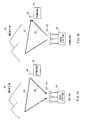
- the number of antennas of each of base station apparatuses 41 and 50 is three.
- FIG.2A in an uplink (transmission from a terminal to a base station), a signal transmitted from terminal apparatus 45 through antenna 46 arrives at antennas 42 to 44 of base station apparatus 41 while being reflected by, for example, mountain 47.
- FIG.2B in a downlink (transmission from the base station to the terminal), a signal transmitted from base station apparatus 50 through antennas 51 to 53 arrives at antenna 55 of terminal apparatus 54 while being reflected by, for example, mountain 56.
- the thus obtained propagation paths 48, 49, 57 and 58 are called multipath propagation path, and a technique for compensating the multipath propagation is called equalizing.
- the communication quality generally deteriorates when the multipath propagation cannot be compensated.
- the communication quality varies in propagation paths 57 and 58 respectively as the terminal moves. Accordingly, in the multipath propagation, it is important to detect a direction (path) in which an optimal communication quality is obtained.
- the weight for transmission is not selected based on the received level of the desired signal of the received signal obtained by adaptive array antenna combining, a signal cannot be transmitted with an optimal weight, resulting in the problem that the apparatus does not recognize whether the level of the desired signal for a communication partner is increased.
- an optimal propagation path in other words, a transmission weight
- the timing arriving at the communication partner varies each time the transmission timing is selected, resulting in the problem that the timing detection at the communication partner becomes difficult.
- An object of the present invention is to achieve a base station apparatus capable of recognizing a state of power of a desired signal of a communication partner, and facilitating timing detection of the communication partner.
- the inventors of the present invention pay attention to that a radiation pattern is formed by controlling weights in adaptive array antenna processing, and thereby an unnecessary signal is cancelled and the received quality is improved, found out that the transmission quality can be improved by performing transmission to the direction in which high received quality is obtained, and achieved the present invention.
- the main point of the present invention is to detect a timing for each incoming signal, perform adaptive array antenna reception with the timing for each incoming signal, calculate a received level of a desired signal using power of adaptive array antenna received result for each incoming signal, select a weight for the adaptive array antenna received result of the desired signal with a higher received level, select a timing of the desired signal with the higher received level, control the transmission timing based on the selected timing, and transmit a signal with the selected weight.
- the base station apparatus of the present invention determines a transmission direction from a direction of arrival of the desired signal, the apparatus can transmit a signal only to the direction in which the desired signal comes, thus enabling the transmission side to compensate the multipath propagation.
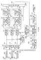
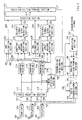
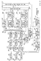
- FIG.3 is a block diagram illustrating a configuration of a base station apparatus according to Embodiment 1 of the present invention.
- Signals received at antennas 101 to 103 are input as received signals 107 to 109 to radio reception section 110 respectively through duplexers 104 to 106.
- Radio reception section 110 executes amplification, frequency conversion, and A/D conversion on the received signals respectively to output as baseband signals or IF signals 111 to 113.
- Timing detection section 123 calculates an optimal reception timing.
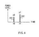
- the calculation of the optimal reception timing is, tor example, executed as follows: A pattern known in a transmitter and receiver is inserted into a frame, and the transmitter transmits the data. The receiver performs A/D conversion at a rate a few to tens times the symbol time, and performs the correlation calculation with the known symbols. Then, the receiver detects the time at which the correlation calculation result is obtained at a high power level as the optimal reception timing. Specifically, as illustrated in FIG.4, time t0 at which power level 201 is p0 and time t1 at which power level 202 is p1 are detected as the optimal reception timings.
- Signal 124 at times t0 and t1 is output to thinning selection sections 114 to 116.
- Thinning selection sections 114 to 116 output received signals 117 to 119 at time t0 to adaptive array antenna reception section 125, and further output received signals 120 to 122 at time t1 to adaptive array antenna reception section 128, respectively.
- the number of adaptive array antenna reception sections is determined as appropriate corresponding to the propagation environment. In such a case, the optimal reception timings of which the number is equivalent to the number of reception sections are detected in descending order of power level of the correlation calculation result in timing detection section 123.
- Adaptive array antenna reception sections 125 and 128 combine the respective received signals from three antennas 101 to 103 so that the desired signal is optimized. Then, adaptive array antenna reception sections 125 and 128 respectively output the combined results 126 and 129 and weights 127 and 130 to be multiplied the received signal from each antenna. The combined results 126 and 129 are respectively output to desired signal level detection sections 131 and 133.
- Desired signal level detection sections 131 and 133 measure respective received levels of the combined results (desired signals) 126 and 129. The measured received levels are output to selection section 135. At this time, weights 127 and 130 are output to selection section 135. Selection section 135 selects the weight for the desired signal with the higher measured received level.
- transmission signal 137 is data modulated in modulation section 138, and output to radiation pattern forming section 140 as modulated signal 139.
- Radiation pattern forming section 140 multiplies the modulated signal by weight 136 so as to maximize the desired signal level.
- Multiplied results 141 to 143 are output to radio transmission section 144, then therein frequency converted and amplified, and transmitted from antennas 101 to 103 as transmission signals 145 to 147 through antenna duplexers 104 to 106, respectively.
- the transmission timings at this point are controlled by transmission timing control signal 149 from transmission timing control section 148.
- Received signals at the times obtained by the timing detection are subjected to adaptive array antenna processing in adaptive array antenna reception sections 125 and 128 so that desired signals are extracted at the optimal reception timing. Thereby, it is possible to extract the desired signal.
- This adaptive array antenna reception is descried in "Waveform equalizing technology for digital mobile communications " (Torikepps, pages 101 to 116).
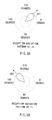
- FIG.5A illustrates radiation pattern 301 at reception time t0
- FIG.5B illustrates radiation pattern 302 at reception time t1.
- adaptive array antenna reception sections 125 and 128 output the resultant signal to desired signal level detection sections 131 and 133, which calculate the received power level of the respective desired signals to detect the desired signal received levels.
- the calculated received levels 132 and 134 are output to selection section 135.
- Selection section 135 compares the two levels to select higher one, and at this point, the weight to form the radiation pattern is input to selection section 135.
- the weight for the desired signal selected in selection section 135 is output to radiation pattern forming section 140, and based on the weight, the radiation pattern for transmission is formed. A transmission signal is transmitted according to the radiation pattern. At this point, the transmission timing is controlled by transmission timing control section 148.
- the weight for transmission is selected with the desired signal power level of the received signal obtained by the adaptive array antenna combining, and the transmission is performed according to the weight, it is possible to perform the transmission in the direction in which the received condition is good. Therefore, since a signal is not transmitted in the direction in which the unnecessary signal arrives, it is possible for the transmission side to compensate the multipath propagation. Consequently, it is not necessary for a receiver to be provided with highly techniques such as an equalizer.
- the base station apparatus of this embodiment since a signal is not transmitted in the direction in which the unnecessary signal arrives, the area that the transmitted signal reaches becomes small. Therefore, it is possible to improve the spectral efficiency in the downlink. Furthermore, since the reversibility of the propagation path is utilized, it is possible to transmit in the downlink (uplink) a signal using a propagation path in which the desired signal power level in the uplink (downlink) is high, and as a result, the desired signal power level in the downlink (uplink) becomes larger.
- the base station apparatus of Embodiment 1 transmits a signal with the radiation pattern that maximizes the received desired signal power level.
- the time that maximizes the desired signal power level varies, as illustrated in FIG.2
- the timing at which the signal arrives at the communication partner varies. Accordingly, such a case makes it difficult for the communication partner to accurately detect the timing of the received signal. Therefore, Embodiment 2 explains the case that the transmission is performed while correcting the timing at which the signal arrives at a communication partner to be constant, whereby the difficulties of timing detection at the communication partner are reduced.
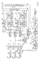
- FIG.6 is a block diagram illustrating a configuration of a base station apparatus according to Embodiment 2 of the present invention.
- the same section as in the base station illustrated in FIG.3 is given the same mark as in FIG.3 to omit the explanation thereof.
- Received signals at the times obtained by the timing detection are subjected to adaptive array antenna processing in adaptive array antenna reception sections 125 and 128 so that desired signals are extracted at the optimal reception timing. Thereby, it is possible to extract the desired signal.
- adaptive array antenna reception sections 125 and 128 output the resultant signal to desired signal level detection sections 131 and 133, which calculate the received power level of the respective desired signals to detect the desired signal received levels.
- the calculated received levels are output to selection section 135.
- Selection section 135 compares the two levels to select higher one, and at this point, the weight to form the radiation pattern is input to selection section 135.
- the weight for the desired signal selected in selection section 135 is output to radiation pattern forming section 140, and based on the weight, the radiation pattern for transmission is formed.
- Received signals at the times obtained by the timing detection are subjected to adaptive array antenna processing in adaptive array antenna reception sections 125 and 128 so that desired signals are extracted at the optimal reception timing. Thereby, it is possible to extract the desired signal.
- This adaptive array antenna reception is descried in "Waveform Equalizing Technology for Digital Mobile Communication” (Triceps Library (TR) 1, page 101-116).
- FIG.5A illustrates radiation pattern 301 at reception time t0
- FIG.5B illustrates radiation pattern 302 at reception time t1.
- adaptive array antenna reception sections 125 and 128 output the resultant signal to desired signal level detection sections 131 and 133, which calculate the received power level of the respective desired signals to detect the desired signal received levels.
- the calculated received levels are output to selection section 135.
- Selection section 135 compares the two levels to select higher one, and at this point, the weight to form the radiation pattern is input to selection section 135.
- the weight for the desired signal selected in selection section 140 is output to radiation pattern forming section 140, and based on the weight, the radiation pattern for transmission is formed.
- the timing corresponding to the desired signal selected in selection section 135 is output to transmission timing control section 148. Then, in the same way as in Embodiment 1, a transmission signal is transmitted according to the radiation pattern. At this point, the transmission timing is controlled based on the selected timing.
- the time required for propagation path A is t0 and that the time required for propagation path B is t1.
- MS mobile station
- BS base station
- the reception side receives signal S0 passed through propagation path A and signal S1 passed through propagation path B. Therefore, the time taken for signal S0 to pass through the propagation is t0, and the time taken for signal S1 to pass through the propagation path is t1.
- the transmission is controlled to transmit a signal faster by t1-t0.
- a signal is transmitted at a timing faster than the standard transmission timing by a time difference between the time at which the desired signal is received with the maximum level and the time at which the desired signal is received with the second maximum level.
- the weight for transmission is selected with the desired signal power level of the received signal obtained by the adaptive array antenna combining, the transmission is performed according to the weight, and concurrently the transmission timing is controlled based on the timing of the selected desired signal. Therefore, it is possible to transmit a signal while correcting the timing at which the signal arrives at the communication partner to be constant, and to reduce the difficulties of timing detection at the communication partner, when the time that maximizes the received desired signal power level varies, in addition to the effects obtained in Embodiment 1.
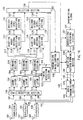
- FIG.7 is a block diagram illustrating a configuration of a base station apparatus according to Embodiment 3 of the present invention.
- the same section as in the base station illustrated in FIG.3 is given the same mark as in FIG.3 to omit the explanation thereof.
- the base station apparatus illustrated FIG.7 is provided with DOA (Direction of Arrival) estimation sections 507 and 508 which respectively estimate the direction of arrival of a desired signal of the received signal at time t0 or t1 selected in thinning selection sections 114 to 116, and further with radiation pattern forming section 512 which calculates the weight to form the radiation pattern based on the direction of arrival of the desired signal with the maximum desired signal received level selected in selection section 135.
- DOA Direction of Arrival
- Received signals at the times obtained by the timing detection are subjected to adaptive array antenna processing in adaptive array antenna reception sections 125 and 128 so that desired signals are extracted at the optimal reception timing. Thereby, it is possible to extract the desired signal.
- received signals 501 to 503 and 504 to 506 are respectively output to DOA estimation sections 507 and 508.
- DOA estimation section 507 estimates the direction of arrival of the desired signal of the received signal at time t0, and outputs the estimated direction of arrival to selection section 135.
- DOA estimation section 508 estimates the direction of arrival of the desired signal of the received signal at time t1, and outputs the estimated direction of arrival to selection section 135.
- the DOA (Direction of Arrival) estimation technique is, for example, explained in "Adaptive Signal Processing Technology with Array Antenna and Introduction Course for High-Resolution Arrival Wave Estimation", page 62-76, published by the IEICE. Further, the radiation pattern forming technique is described in the antenna engineering handbook (OHM SHA, page 200-205).
- Selection section 135 selects the direction of arrival of the desired signal with the higher detected received level, and outputs the direction of arrival to radiation pattern forming section 512. Based on the direction of arrival, radiation pattern forming section 512 calculates the weight to form the radiation pattern. Weight 513 is output to radiation pattern forming section 140 of the transmission site.
- the transmission site forms the radiation pattern for transmission based on the weight calculated in radiation pattern forming section 512 of the reception site.
- the transmission signal is, in the same way as in Embodiment 1, transmitted according to the radiation pattern.
- the transmission timing is controlled by transmission timing control section 148.
- the base station apparatus of this embodiment since the direction for transmission is selected with the desired signal power level of the received signal obtained by the adaptive array antenna combining, the weight is calculated based on the selected direction, the radiation pattern for transmission is formed using the weight, and the transmission is performed according to the radiation patter, it is possible to perform the transmission only in the direction of the desired signal arriving arrives, enabling the transmission side to compensate the multipath propagation. Consequently, it is not necessary for a receiver to be provided with highly techniques such as an equalizer.
- the base station apparatus of this embodiment since a signal is transmitted only in the direction of the desired signal arriving arrives, the area that the transmitted signal reaches becomes small. Therefore, it is possible to improve the spectral efficiency in the downlink. Furthermore, since the reversibility of the propagation path is utilized, it is possible to transmit in the downlink (uplink) a signal with a propagation path in which the desired signal power level in the uplink (downlink) is high, and as a result, the desired signal power level in the downlink (uplink) becomes larger.
- the base station apparatus of Embodiment 3 transmits a signal with the radiation pattern that maximizes the received desired signal power level.
- the time that maximizes the desired signal power level varies, as illustrated in FIG.2
- the timing at which the signal arrives at the communication partner varies. Accordingly, such a case makes it difficult for the communication partner to accurately detect the timing of the received signal. Therefore, Embodiment 4 explains the case that the transmission is performed while correcting the timing at which the signal arrives at a communication partner to be constant, whereby the difficulties of timing detection at the communication partner are reduced.
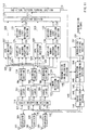
- FIG.8 is a block diagram illustrating a configuration of a base station apparatus according to Embodiment 4 of the present invention.
- the same section as in the base station apparatus illustrated in FIG.7 is given the same mark as in FIG.7 to omit the explanation thereof.
- Received signals at the times obtained by the timing detection are subjected to adaptive array antenna processing in adaptive array antenna reception sections 125 and 128 so that desired signals are extracted at the optimal reception timing. Thereby, it is possible to extract the desired signal.
- received signals 501 to 503 and 504 to 506 are respectively output to DOA estimation sections 507 and 508.
- DOA estimation section 507 estimates the direction of arrival of the desired signal of the received signal at time t0, and outputs the estimated direction of arrival to selection section 135.
- DOA estimation section 508 estimates the direction of arrival of the desired signal of the received signal at time t1, and outputs the estimated direction of arrival to selection section 135.
- Selection section 135 selects the direction of arrival of the desired signal with the higher detected received level, and outputs the direction of arrival to radiation pattern forming section 512. Based on the direction of arrival, radiation pattern forming section 512 calculates the weight to form the radiation pattern. Weight 513 is output to radiation pattern forming section 140 of the transmission site.
- Timing 601 corresponding to the desired signal selected in selection section 135 is output to transmission timing control section 148. Then, the transmission signal is, in the same way as in Embodiment 2, transmitted according to the radiation pattern, and the transmission timing is controlled based on the selected timing.
- the weight is calculated based on the selected direction, the radiation pattern for transmission is formed using the weight, the transmission is performed according to the radiation pattern, and concurrently the transmission timing is controlled based on the timing of the selected desired signal. Therefore, it is possible to transmit a signal while correcting the timing at which the signal arrives at the communication partner to be constant, and to reduce the difficulties of timing detection at the communication partner, when the time that maximizes the received desired signal power level varies, in addition to the effects obtained in Embodiment 3.
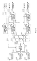
- FIG.9 is a block diagram illustrating a configuration of a base station apparatus according to Embodiment 5 of the present invention.
- Signals received at antennas 101 to 103 are input as received signals 107 to 109 to radio reception section 110 through duplexers 104 to 106, respectively.
- Radio reception section 110 executes amplification, frequency conversion, and A/D conversion on the received signals respectively to output as baseband signals or IF signals 111 to 113.
- These signals 111 to 113 are output to correlators 701 to 703, and therein subjected to despreading processing with a spreading code used in the transmission.
- the despread signals 704 to 706 are output to thinning selection sections 114 to 116, while being outputting to timing detection section 123.
- Timing detection section 123 calculates the optimal reception timing, in the same way as in Embodiment 1.
- Signal 124 at the optimal reception timing is output to thinning selection sections 114 to 116.
- Thinning selection sections 114 to 116 output received signals 117 to 119 at time t0 to adaptive array antenna reception section 125, and further output received signals 120 to 122 at time t1 to adaptive array antenna reception section 128, respectively.
- the number of adaptive array antenna reception sections is determined as appropriate corresponding to the propagation environment. In such a case, the optimal reception timings of which the number is equivalent to the number of reception sections are detected in descending order of power level of the correlation calculation result in timing detection section 123.
- Adaptive array antenna reception sections 125 and 128 combine the respective received signals from three antennas 101 to 103 so that the desired signal is optimized. Then, adaptive array antenna reception sections 125 and 128 respectively output the combined results 126 and 129 and weights 127 and 130 to be multiplied the received signal from each antenna. The combined results 126 and 129 are respectively output to desired signal level detection sections 131 and 133.
- Desired signal level detection sections 131 and 133 measure respective received levels of the combined results (desired signals) 126 and 129. The measured received levels are output to selection section 135. At this time, weights 127 and 130 are output to selection section 135. Selection section 135 selects the weight for the desired signal with the higher measured received level.
- transmission signal 137 is data modulated and spread with the spreading code in modulation/spreading section 707.
- the modulated and spread signal 708 is output to radiation pattern forming section 140.
- Radiation pattern forming section 140 multiplies the modulated signal by weight 136 so as to maximize the desired signal level.
- Multiplied results 141 to 143 are output to radio transmission section 144, then therein frequency converted and amplified, and transmitted from antennas 101 to 103 through antenna duplexers 104 to 106, respectively.
- the transmission timings at this point are controlled by transmission control signal 149 from transmission timing control section 148.
- Received signals are subjected to baseband processing in radio reception section 110, and then despreading processing in correlators 701 to 703. Then, the received signals at the times obtained by the timing detection in timing detection section 123 are, in the same way as in Embodiment 1, subjected to adaptive array antenna processing in adaptive array antenna reception sections 125 and 128 so that desired signals are extracted at the optimal reception timing. Thereby, it is possible to extract the desired signal.
- adaptive array antenna reception sections 125 and 128 output the resultant signal to desired signal level detection sections 131 and 133, which calculate the received power level of the respective desired signals to detect the desired signal received levels.
- the calculated received levels are output to selection section 135.
- Selection section 135 compares the two levels to select higher one, and at this point, the weight to form the radiation pattern is input to selection section 135.
- the weight for the desired signal selected in selection section 135 is output to radiation pattern forming section 140, and based on the weight, the radiation pattern for transmission is formed. A transmission signal is transmitted according to the radiation pattern. At this point; the transmission timing is controlled by transmission timing control section 148.
- the base station apparatus of this embodiment also in the radio communication system with the spread spectrum communication system, since the weight for transmission is selected with the desired signal power level of the received signal obtained by the adaptive array antenna combining, and the transmission is performed according to the weights a signal is not transmitted in the direction in which the unnecessary signal arrives, and it is possible for the transmission side to compensate the multipath propagation. Consequently, it is not necessary for a receiver to be provided with highly techniques such as an equalizer.
- the base station apparatus of this embodiment since a signal is not transmitted in the direction in which the unnecessary signal arrives, the area that the transmitted signal reaches becomes small. Therefore, it is possible to improve the spectral efficiency in the downlink. Furthermore, since the reversibility of the propagation path is utilized, it is possible to transmit in the downlink (uplink) a signal with a propagation path in which the desired signal power level in the uplink (downlink) is high, and as a result, the desired signal power level in the downlink (uplink) becomes larger.
- the base station apparatus of Embodiment 5 transmits a signal with the radiation pattern that maximizes the received desired signal power level.
- the time that maximizes the desired signal power level varies, as illustrated in FIG.2
- the timing at which the signal arrives at the communication partner varies. Accordingly, such a case makes it difficult for the communication partner to accurately detect the timing of the received signal. Therefore, Embodiment 6 explains the case that the transmission is performed while correcting the timing at which the signal arrives at a communication partner to be constant, whereby the difficulties of timing detection at the communication partner are reduced.
- FIG.10 is a block diagram illustrating a configuration of a base station apparatus according to Embodiment 6 of the present invention.
- the same section as in the base station illustrated in FIG.9 is given the same mark as in FIG.9 to omit the explanation thereof.
- Received signals are subjected to baseband processing in radio reception section 110, and then despreading processing in correlators 701 to 703. Then, received signals at the times obtained by the timing detection in timing selection section 123 are subjected to adaptive array antenna processing in adaptive array antenna reception sections 125 and 128 so that desired signals are extracted at the optimal reception timing. Thereby, it is possible to extract the desired signal.
- the radiation pattern points to the desired signal, and a small radiation pattern (called null) is formed in the direction of unnecessary signals (delayed versions of the desired signal arriving at different times due to different propagation paths or signals from another transmitted). In other words, the radiation pattern is formed with the weight.
- adaptive array antenna reception sections 125 and 128 output the resultant signal to desired signal level detection sections 131 and 133, which calculate the received power level of the respective desired signals to detect the desired signal received levels.
- the calculated received levels are output to selection section 135.
- Selection section 135 compares the two levels to select higher one, and at this point, the weight to form the radiation pattern is input to selection section 135.
- the weight for the desired signal selected in selection section 135 is output to radiation pattern forming section 140, and based on the weight, the radiation pattern for transmission is formed.
- Received signals at the times obtained by the timing detection are subjected to adaptive array antenna processing in adaptive array antenna reception sections 125 and 128 so that desired signals are extracted at the optimal reception timing. Thereby, it is possible to extract the desired signal.
- adaptive array antenna reception sections 125 and 128 output the resultant signal to desired signal level detection sections 131 and 133, which calculate the received power level of the respective desired signals to detect the desired signal received levels.
- the calculated received levels are output to selection section 135.
- Selection section 135 compares the two levels to select higher one, and at this point, the weight to form the radiation pattern is input to selection section 135.
- the weight for the desired signal selected in selection section 140 is output to radiation pattern forming section 140, and based on the weight, the radiation pattern for transmission is formed.
- the timing corresponding to the desired signal selected in selection section 135 is output to transmission timing control section 148. Then, in the same way as in Embodiment 1, a transmission signal is transmitted according to the radiation pattern. At this point, the transmission timing is controlled based on the selected timing.
- the time required for propagation path A is t0 and that the time required for propagation path B is t1.
- MS mobile station
- BS base station
- the reception side receives signal S0 passed through propagation path A and signal S1 passed through propagation path B. Therefore, the time taken for signal S0 to pass through the propagation path is t0, and the time taken for signal S1 to pass through the propagation path is t1.
- the directional transmission is assumed herein, when the BS transmits a signal at time T, the signal is transmitted through either of propagation path A or B. Accordingly, the reception time of the signal through propagation path A is T+t0, and the reception time of the signal through propagation path B is T+t1. To make the times at which the signals arrive at the MS same, when propagation path A is a reference, it is necessary to transmit at time of T-(t1-t0). Accordingly, the transmission is controlled to transmit a signal faster by t1-t0.
- the weight for transmission is selected with the desired signal power level of the received signal obtained by the adaptive array antenna combining, the transmission is performed according to the weight, and concurrently the transmission timing is controlled based on the timing of the selected desired signal. Therefore, it is possible to transmit a signal while correcting the timing at which the signal arrives at the communication partner to be constant, and to reduce the difficulties of timing detection at the communication partner, when the time that maximizes the received desired signal power level varies, in addition to the effects obtained in Embodiment 1.
- FIG.11 is a block diagram illustrating a configuration of a base station apparatus according to Embodiment 7 of the present invention.
- the same section as in the base station apparatus illustrated in FIG.9 is given the same mark as in FIG.9 to omit the explanation thereof.
- the base station apparatus illustrated FIG.11 is provided with DOA (direction of arrival) estimation sections 507 and 508 which respectively estimate the direction of arrival of a desired signal of the received signal at time t0 or t1 selected in thinning selection sections 114 to 116, and further with radiation pattern forming section 512 which calculates the weight to form the radiation pattern based on the direction of arrival of the desired signal with the maximum desired signal received level selected in selection section 135.
- radiation pattern forming section 512 which calculates the weight to form the radiation pattern based on the direction of arrival of the desired signal with the maximum desired signal received level selected in selection section 135.
- Received signals are subjected to baseband processing in radio reception section 110, and then despreading processing in correlators 701 to 703. Then, received signals at the times obtained by the timing detection in timing detection section 123 are subjected to adaptive array antenna processing in adaptive array antenna reception sections 125 and 128 so that desired signals are extracted at the optimal reception timing. Thereby, it is possible to extract the desired signal. Further, received signals 501 to 503 and 504 to 506 are respectively output to DOA estimation sections 507 and 508. DOA estimation section 507 estimates the direction of arrival of the desired signal of the received signal at time t0, and outputs the estimated direction of arrival to selection section 135. Further, in the same way as in Embodiment 3, DOA estimation section 508 estimates the direction of arrival of the desired signal of the received signal at time t1, and outputs the estimated direction of arrival to selection section 135.
- Selection section 135 selects the direction of arrival of the desired signal with the higher detected received level, and outputs the direction of arrival to radiation pattern forming section 512. Based on the direction of arrival, radiation pattern forming section 512 calculates the weight to form the radiation pattern. Weight 513 is output to radiation pattern forming section 140 of the transmission site.
- the transmission site forms the radiation pattern for transmission based on the weight calculated in radiation pattern forming section 512 of the reception site.
- the transmission signal is, in the same way as in Embodiment 1, transmitted according to the radiation pattern.
- the transmission timing is controlled by transmission timing control section 148.
- the base station apparatus of this embodiment also in the radio communication system with the spread spectrum communication system, since the direction for transmission is selected with the desired signal power level of the received signal obtained by the adaptive array antenna combining, the weight is calculated based on the selected direction, the radiation pattern for transmission is formed using the weight, and the transmission is performed according to the radiation patter, it is possible to perform the transmission only in the direction of the desired signal arriving arrives, enabling the transmission side to compensate the multipath propagation. Consequently, it is not necessary for a receiver to be provided with highly techniques such as an equalizer.
- the base station apparatus of this embodiment since a signal is transmitted only in the direction of the desired signal arriving arrives, the area that the transmitted signal reaches becomes small. Therefore, it is possible to improve the spectral efficiency in the downlink. Furthermore, since the reversibility of the propagation path is utilized, it is possible to transmit in the downlink (uplink) a signal with a propagation path in which the desired signal power level in the uplink (downlink) is high, and as a result, the desired signal power level in the downlink becomes larger.
- the base station apparatus of Embodiment 7 transmits a signal with the radiation pattern that maximizes the received desired signal power level.
- the time that maximizes the desired signal power level varies, as illustrated in FIG.2
- the timing at which the signal arrives at the communication partner varies. Accordingly, such a case makes it difficult for the communication partner to accurately detect the timing of the received signal. Therefore, Embodiment 8 explains the case that the transmission is performed while correcting the timing at which the signal arrives at a communication partner to be constant, whereby the difficulties of timing detection at the communication partner are reduced.
- FIG.12 is a block diagram illustrating a configuration of a base station apparatus according to Embodiment 8 of the present invention.
- the same section as in the base station apparatus illustrated in FIG.11 is given the same mark as in FIG.11 to omit the explanation thereof.
- Received signals are subjected to baseband processing in radio reception section 110, and then despreading processing in correlators 701 to 703. Then, received signals at the times obtained by the timing detection in timing detection section 123 are subjected to adaptive array antenna processing in adaptive array antenna reception sections 125 and 128 so that desired signals are extracted at the optimal reception timing. Thereby, it is possible to extract the desired signal. Further, received signals 501 to 503 and 504 to 506 are respectively output to DOA estimation sections 507 and 508. In the same way as in Embodiment 3, DOA estimation section 507 estimates the direction of arrival of the desired signal of the received signal at time t0, and outputs the estimated direction of arrival to selection section 135. DOA estimation section 508 estimates the direction of arrival of the desired signal of the received signal at time t1, and outputs the estimated direction of arrival to selection section 135.
- Selection section 135 selects the direction of arrival of the desired signal with the higher detected received level, and outputs the direction of arrival to radiation pattern forming section 512. Based on the direction of arrival, radiation pattern forming section 512 calculates the weight to form the radiation pattern. Weight 513 is output to radiation pattern forming section 140 of the transmission site.
- Timing 601 corresponding to the desired signal selected in selection section 135 is output to transmission timing control section 148. Then, the transmission signal is, in the same way as in Embodiment 2, transmitted according to the radiation pattern, and the transmission timing is controlled based on the selected timing.
- the base station apparatus of this embodiment also in the radio communication system with the spread spectrum communication system, since the direction for transmission is selected with the desired signal power level of the received signal obtained by the adaptive array antenna combining, the weight is calculated based on the selected direction, the radiation pattern for transmission is formed using the weight, the transmission is performed according to the radiation patter, and concurrently the transmission timing is controlled based on the timing of the selected desired signal. Therefore, it is possible to transmit a signal while correcting the timing at which the signal arrives at the communication partner to be constant, and to reduce the difficulties of timing detection at the communication partner, when the time that maximizes the received desired signal power level varies, in addition to the effects obtained in Embodiment 3.
- FIG.13 is a block diagram illustrating a configuration of a base station apparatus according to Embodiment 9.
- the base station apparatus illustrated in FIG.13 is configured corresponding to the case that the number of communication partners is 2.
- this embodiment is similarly applicable to the case that the number of communication partners is more than 2.
- the configuration of the reception site is the same as in the above-mentioned embodiments, and the explanation thereof is omitted.
- the operation for performing adaptive array antenna reception on signals from a plurality of communication partners, and detecting the weight and timing that maximize the desired signal received level is as described in the above-mentioned embodiments.
- Transmission signal 1107 for communication partner 1 is data modulated and spread in modulation/spreading section 1108, and output to radiation pattern forming section 1110.
- Radiation pattern forming section 1110 multiplies the modulated signal by the weight for communication partner 1, and outputs the multiplied signals 1112 to 1114 to adders 1123 to 1125.
- transmission signal 1115 for communication partner 2 is data modulated and spread in modulation/spreading section 1116, and output to radiation pattern forming section 1118.
- Radiation pattern forming section 1118 multiplies the modulated signal by the weight for communication partner 2, and outputs the multiplied signals 1112 to 1114 to adders 1123 to 1125.
- Radio transmission section 1129 executes the frequency conversion and amplification on signals 1126 to 1128 obtained by adding the signals for communication partners 1 and 2, and resultant signals 1130 to 1132 are transmitted from antennas 1101 to 1103 through antenna duplexers 1104 to 1106, respectively.
- transmission timing 1136 is controlled by transmission timing control section 1135 based on two types of time information 1133 and 1134 each indicative of the time that maximizes the desired signal received level for respective communication partner.
- the timing control is performed in such a manner that the unit time for the timing control is within a one-chip duration time.
- a spreading code capable of keeping the orthogonality in the case where the timing differs by one chip such as the orthogonal Gold code
- the spreading code is not the orthogonal Gold code, in the case where the cross-correlation becomes small at the time the timing differs by one chip, it is possible to carry out this embodiments into practice.
- the base station apparatus of this embodiment in the radio communication system with the spread spectrum communication system, since the weight and timing for transmission are selected with the desired signal power level of the received signal obtained by the adaptive array antenna combining, the area that the transmitted signal reaches becomes small, and therefore it is possible to improve the spectral efficiency in the downlink.
- the base station apparatus of this embodiment by the use of the reversibility of the propagation path, a signal is transmitted in the downlink with a propagation path in which the desired signal power level in the uplink is large, the desired signal power level in the downlink becomes large also. Furthermore, when the time that maximizes the received desired signal power level varies, it is possible to reduce the difficulties of timing detection at the communication partner by transmitting a signal while correcting the timing at which the signal arrives at the communication partner to be constant.
- the base station apparatus of any of the above-mentioned Embodiments 1 to 9 is applicable to a communication terminal apparatus such as a mobile station and base station apparatus in a digital radio communication system.
- Embodiments 1 to 9 are capable of being carried into practice in a combination thereof as appropriate. Further, the present invention is not limited to the above-mentioned embodiments, and is capable of being carried into practice with various modifications thereof.
- the base station apparatus of the present invention is capable of recognizing the state of desired signal power at a communication partner, and of facilitating the timing detection at the communication partner. Thereby, it is possible for the base station apparatus to transmit a signal only in the direction of the desired signal arriving, enabling the transmission side to compensate the multipath propagation. Therefore, it is not necessary for a receiver to be provided with highly techniques such as an equalizer. Further, when the time that maximizes the received desired signal power level varies, it is possible to transmit a signal while correcting the timing at which the signal arrives at the communication partner to be constant, and to reduce the difficulties of timing detection at the communication partner.
- the present invention is applicable to digital radio communication systems with, for example, portable telephones.
Landscapes
- Engineering & Computer Science (AREA)
- Computer Networks & Wireless Communication (AREA)
- Signal Processing (AREA)
- Mobile Radio Communication Systems (AREA)
- Radio Transmission System (AREA)
- Transceivers (AREA)
- Variable-Direction Aerials And Aerial Arrays (AREA)
Applications Claiming Priority (3)
| Application Number | Priority Date | Filing Date | Title |
|---|---|---|---|
| JP10219287A JP2000059278A (ja) | 1998-08-03 | 1998-08-03 | 無線通信装置 |
| JP21928798 | 1998-08-03 | ||
| PCT/JP1999/003943 WO2000008778A1 (en) | 1998-08-03 | 1999-07-23 | Base station device and radio communication method |
Publications (2)
| Publication Number | Publication Date |
|---|---|
| EP1028544A1 true EP1028544A1 (de) | 2000-08-16 |
| EP1028544A4 EP1028544A4 (de) | 2006-02-15 |
Family
ID=16733147
Family Applications (1)
| Application Number | Title | Priority Date | Filing Date |
|---|---|---|---|
| EP99931501A Withdrawn EP1028544A4 (de) | 1998-08-03 | 1999-07-23 | Basisstation und funkübertragungsverfahren |
Country Status (8)
| Country | Link |
|---|---|
| US (1) | US6771984B1 (de) |
| EP (1) | EP1028544A4 (de) |
| JP (1) | JP2000059278A (de) |
| CN (1) | CN1158787C (de) |
| AU (1) | AU4799999A (de) |
| BR (1) | BR9906665A (de) |
| CA (1) | CA2304785A1 (de) |
| WO (1) | WO2000008778A1 (de) |
Cited By (4)
| Publication number | Priority date | Publication date | Assignee | Title |
|---|---|---|---|---|
| EP1361679A3 (de) * | 2002-05-07 | 2005-04-13 | Matsushita Electric Industrial Co., Ltd. | Funkkommunikationsvorrichtung und Verfahren zum Schätzen der Einfallsrichtung |
| EP1345337A3 (de) * | 2002-03-12 | 2005-04-27 | Matsushita Electric Industrial Co., Ltd. | Adaptive Antenne einer Basisstation mit Abschätzung der Empfangsrichtung |
| US7599401B2 (en) | 2003-02-06 | 2009-10-06 | Panasonic Corporation | Transmission device and transmission method |
| EP2528247A1 (de) * | 2004-11-02 | 2012-11-28 | NTT DoCoMo, Inc. | Basisstation, Funknetzwerksteuerstation und Funkkommunikationsverfahren |
Families Citing this family (15)
| Publication number | Priority date | Publication date | Assignee | Title |
|---|---|---|---|---|
| JP2002026789A (ja) * | 1998-09-11 | 2002-01-25 | Matsushita Electric Ind Co Ltd | 通信装置および指向性送信方法 |
| JP2000307489A (ja) | 1999-04-23 | 2000-11-02 | Matsushita Electric Ind Co Ltd | 無線受信装置及び受信タイミング検出方法 |
| KR100508617B1 (ko) | 2000-06-29 | 2005-08-17 | 마츠시타 덴끼 산교 가부시키가이샤 | 기지국 장치, 통신 단말 장치 및 무선 통신 방법 |
| JP2002084217A (ja) * | 2000-09-08 | 2002-03-22 | Matsushita Electric Ind Co Ltd | 基地局装置および到来方向推定方法 |
| JP3679000B2 (ja) * | 2000-12-21 | 2005-08-03 | 松下電器産業株式会社 | 無線送信装置及び無線送信方法 |
| JP4531969B2 (ja) * | 2000-12-21 | 2010-08-25 | 三菱電機株式会社 | アダプティブアンテナ受信装置 |
| JP4726306B2 (ja) * | 2001-01-31 | 2011-07-20 | パナソニック株式会社 | 無線通信システム、移動端末局及び方位決定方法 |
| GB2371947B (en) * | 2001-02-01 | 2005-02-23 | Fujitsu Ltd | Communications systems |
| KR20050103315A (ko) * | 2002-07-19 | 2005-10-28 | 인터디지탈 테크날러지 코포레이션 | 수신 다이버시티를 갖는 블록 전송을 위한 그룹형 직렬간섭 제거 |
| JP4217043B2 (ja) * | 2002-09-20 | 2009-01-28 | 京セラ株式会社 | アダプティブアレイ無線通信装置、受信レベル表示方法、受信レベル調整方法、受信レベル表示プログラム、および受信レベル調整プログラム |
| US8477830B2 (en) | 2008-03-18 | 2013-07-02 | On-Ramp Wireless, Inc. | Light monitoring system using a random phase multiple access system |
| US8520721B2 (en) * | 2008-03-18 | 2013-08-27 | On-Ramp Wireless, Inc. | RSSI measurement mechanism in the presence of pulsed jammers |
| US20100195553A1 (en) | 2008-03-18 | 2010-08-05 | Myers Theodore J | Controlling power in a spread spectrum system |
| US8958460B2 (en) | 2008-03-18 | 2015-02-17 | On-Ramp Wireless, Inc. | Forward error correction media access control system |
| US8363699B2 (en) | 2009-03-20 | 2013-01-29 | On-Ramp Wireless, Inc. | Random timing offset determination |
Family Cites Families (13)
| Publication number | Priority date | Publication date | Assignee | Title |
|---|---|---|---|---|
| US4752969A (en) * | 1986-01-16 | 1988-06-21 | Kenneth Rilling | Anti-multipath signal processor |
| JP2684888B2 (ja) * | 1991-08-06 | 1997-12-03 | 国際電信電話株式会社 | アダプティブアレイアンテナ制御方式 |
| JP2635503B2 (ja) * | 1992-10-28 | 1997-07-30 | 株式会社エイ・ティ・アール光電波通信研究所 | アレーアンテナの制御方法及び制御装置 |
| EP0595247B1 (de) | 1992-10-28 | 1998-07-15 | Atr Optical And Radio Communications Research Laboratories | Vorrichtung und Verfahren zur Steuerung einer Gruppenantenne mit einer Vielzahl von Antennenelementen |
| GB2281007B (en) * | 1993-08-12 | 1998-04-15 | Northern Telecom Ltd | Base station antenna arrangement |
| US6101399A (en) | 1995-02-22 | 2000-08-08 | The Board Of Trustees Of The Leland Stanford Jr. University | Adaptive beam forming for transmitter operation in a wireless communication system |
| JPH08274687A (ja) | 1995-03-31 | 1996-10-18 | Matsushita Electric Ind Co Ltd | Cdma無線伝送装置およびcdma無線伝送システム |
| IL120574A (en) * | 1996-05-17 | 2002-09-12 | Motorala Ltd | Method and devices for transmitter path weights |
| US6122260A (en) * | 1996-12-16 | 2000-09-19 | Civil Telecommunications, Inc. | Smart antenna CDMA wireless communication system |
| JP3300252B2 (ja) | 1997-04-02 | 2002-07-08 | 松下電器産業株式会社 | 適応送信ダイバーシチ装置及び適応送信ダイバーシチ方法 |
| JP3405111B2 (ja) * | 1997-02-13 | 2003-05-12 | Kddi株式会社 | アレーアンテナの制御方法及び装置 |
| JP3406831B2 (ja) * | 1998-03-19 | 2003-05-19 | 富士通株式会社 | 無線基地局のアレーアンテナシステム |
| US6188915B1 (en) * | 1998-05-19 | 2001-02-13 | Harris Corporation | Bootstrapped, piecewise-asymptotic directivity pattern control mechanism setting weighting coefficients of phased array antenna |
-
1998
- 1998-08-03 JP JP10219287A patent/JP2000059278A/ja active Pending
-
1999
- 1999-07-23 AU AU47999/99A patent/AU4799999A/en not_active Abandoned
- 1999-07-23 EP EP99931501A patent/EP1028544A4/de not_active Withdrawn
- 1999-07-23 CA CA002304785A patent/CA2304785A1/en not_active Abandoned
- 1999-07-23 BR BR9906665-3A patent/BR9906665A/pt not_active IP Right Cessation
- 1999-07-23 US US09/509,047 patent/US6771984B1/en not_active Expired - Fee Related
- 1999-07-23 WO PCT/JP1999/003943 patent/WO2000008778A1/ja not_active Ceased
- 1999-07-23 CN CNB998012491A patent/CN1158787C/zh not_active Expired - Fee Related
Cited By (10)
| Publication number | Priority date | Publication date | Assignee | Title |
|---|---|---|---|---|
| EP1345337A3 (de) * | 2002-03-12 | 2005-04-27 | Matsushita Electric Industrial Co., Ltd. | Adaptive Antenne einer Basisstation mit Abschätzung der Empfangsrichtung |
| US7117016B2 (en) | 2002-03-12 | 2006-10-03 | Matsushita Electric Industrial Co., Ltd. | Adaptive antenna base station apparatus |
| EP1361679A3 (de) * | 2002-05-07 | 2005-04-13 | Matsushita Electric Industrial Co., Ltd. | Funkkommunikationsvorrichtung und Verfahren zum Schätzen der Einfallsrichtung |
| US7263083B2 (en) | 2002-05-07 | 2007-08-28 | Matsushita Electric Industrial Co., Ltd. | Radio communication device and arrival direction estimation method |
| EP1843487A1 (de) | 2002-05-07 | 2007-10-10 | Matsushita Electric Industrial Co., Ltd. | Funkkommunikationsvorrichtung und Verfahren zur Schätzung der Wellenankunftsrichtung |
| US7860064B2 (en) | 2002-05-07 | 2010-12-28 | Matsushita Electric Industrial Co., Ltd. | Radio communication device and arrival direction estimation method |
| US8520641B2 (en) | 2002-05-07 | 2013-08-27 | Panasonic Corporation | Radio communication device and arrival direction estimation method |
| US8532064B2 (en) | 2002-05-07 | 2013-09-10 | Panasonic Corporation | Radio communication device and arrival direction estimation method |
| US7599401B2 (en) | 2003-02-06 | 2009-10-06 | Panasonic Corporation | Transmission device and transmission method |
| EP2528247A1 (de) * | 2004-11-02 | 2012-11-28 | NTT DoCoMo, Inc. | Basisstation, Funknetzwerksteuerstation und Funkkommunikationsverfahren |
Also Published As
| Publication number | Publication date |
|---|---|
| WO2000008778A1 (en) | 2000-02-17 |
| CN1274491A (zh) | 2000-11-22 |
| JP2000059278A (ja) | 2000-02-25 |
| EP1028544A4 (de) | 2006-02-15 |
| AU4799999A (en) | 2000-02-28 |
| CA2304785A1 (en) | 2000-02-17 |
| BR9906665A (pt) | 2000-10-17 |
| CN1158787C (zh) | 2004-07-21 |
| US6771984B1 (en) | 2004-08-03 |
Similar Documents
| Publication | Publication Date | Title |
|---|---|---|
| US6771984B1 (en) | Base station device and radio communication method | |
| US6470194B1 (en) | Base station with improved directivity using adaptive antenna array reception | |
| US7133698B2 (en) | Radio base station apparatus and radio communication method | |
| JP4026858B2 (ja) | 方向性無線通信方法及び装置 | |
| US6415163B1 (en) | Method for transmitting pilot channels and a cellular radio system | |
| EP1361679B1 (de) | Funkkommunikationsvorrichtung und Verfahren zum Schätzen der Einfallsrichtung | |
| US6512917B1 (en) | Radio communication device and transmitting power control method | |
| JP4121560B2 (ja) | 方向性無線通信方法及び装置 | |
| US6393303B1 (en) | Method and apparatus for directional radio communication | |
| KR100591700B1 (ko) | 배열 안테나 시스템에서 신호 경로 탐색 방법 및 이를위한 장치 | |
| US6321066B1 (en) | Method and apparatus for directional radio communication | |
| US6321082B1 (en) | Method and apparatus for directional radio communication | |
| EP1315314A1 (de) | Mobilkommunikationsendgerät, kommunikationsverfahren und programm | |
| US6509872B2 (en) | Adaptive antenna receiving apparatus | |
| JPH11266228A (ja) | 無線基地局のマルチビームアンテナシステム | |
| US6721367B1 (en) | Base station apparatus and radio communication method | |
| US7702287B2 (en) | Communication device, calibration method, and program | |
| GB2380881A (en) | Estimating the angle of arrival at a mobile terminal | |
| WO2002027971A1 (en) | Base station device and radio transmitting method | |
| KR20010112321A (ko) | 무선 기지국 장치, 통신 단말 장치 및 무선 통신 방법 | |
| WO2000031900A1 (en) | Base station and method of transmission power control | |
| EP1583258B1 (de) | Funkkommunikationsvorrichtung mit Antennenfeld | |
| US6628959B1 (en) | Base station and method of transmission power control | |
| GB2396501A (en) | Directing radio beam |
Legal Events
| Date | Code | Title | Description |
|---|---|---|---|
| PUAI | Public reference made under article 153(3) epc to a published international application that has entered the european phase |
Free format text: ORIGINAL CODE: 0009012 |
|
| 17P | Request for examination filed |
Effective date: 20000502 |
|
| AK | Designated contracting states |
Kind code of ref document: A1 Designated state(s): AT BE CH CY DE DK ES FI FR GB GR IE IT LI LU MC NL PT SE |
|
| RBV | Designated contracting states (corrected) |
Designated state(s): DE ES FR GB IT |
|
| A4 | Supplementary search report drawn up and despatched |
Effective date: 20060104 |
|
| RIC1 | Information provided on ipc code assigned before grant |
Ipc: H01Q 3/26 20060101ALI20051229BHEP Ipc: H04B 7/08 20060101AFI20051229BHEP |
|
| 17Q | First examination report despatched |
Effective date: 20070807 |
|
| STAA | Information on the status of an ep patent application or granted ep patent |
Free format text: STATUS: THE APPLICATION IS DEEMED TO BE WITHDRAWN |
|
| 18D | Application deemed to be withdrawn |
Effective date: 20071218 |