EP1027091B1 - Multipurpose catheter - Google Patents
Multipurpose catheter Download PDFInfo
- Publication number
- EP1027091B1 EP1027091B1 EP98947598A EP98947598A EP1027091B1 EP 1027091 B1 EP1027091 B1 EP 1027091B1 EP 98947598 A EP98947598 A EP 98947598A EP 98947598 A EP98947598 A EP 98947598A EP 1027091 B1 EP1027091 B1 EP 1027091B1
- Authority
- EP
- European Patent Office
- Prior art keywords
- cylindrical body
- catheter according
- head
- multipurpose catheter
- inlet
- Prior art date
- Legal status (The legal status is an assumption and is not a legal conclusion. Google has not performed a legal analysis and makes no representation as to the accuracy of the status listed.)
- Expired - Lifetime
Links
- 239000007788 liquid Substances 0.000 claims abstract description 14
- 238000004891 communication Methods 0.000 claims abstract description 5
- KWGRBVOPPLSCSI-WPRPVWTQSA-N (-)-ephedrine Chemical compound CN[C@@H](C)[C@H](O)C1=CC=CC=C1 KWGRBVOPPLSCSI-WPRPVWTQSA-N 0.000 claims abstract 5
- 239000000463 material Substances 0.000 claims description 7
- 229920003023 plastic Polymers 0.000 claims description 7
- 238000007789 sealing Methods 0.000 claims description 7
- 239000012263 liquid product Substances 0.000 claims description 2
- RBTBFTRPCNLSDE-UHFFFAOYSA-N 3,7-bis(dimethylamino)phenothiazin-5-ium Chemical compound C1=CC(N(C)C)=CC2=[S+]C3=CC(N(C)C)=CC=C3N=C21 RBTBFTRPCNLSDE-UHFFFAOYSA-N 0.000 description 4
- 229960000907 methylthioninium chloride Drugs 0.000 description 4
- 210000004291 uterus Anatomy 0.000 description 4
- 208000031968 Cadaver Diseases 0.000 description 3
- 230000000694 effects Effects 0.000 description 3
- 238000002347 injection Methods 0.000 description 3
- 239000007924 injection Substances 0.000 description 3
- 238000002357 laparoscopic surgery Methods 0.000 description 3
- 210000002966 serum Anatomy 0.000 description 3
- 238000012360 testing method Methods 0.000 description 3
- 235000021183 entrée Nutrition 0.000 description 2
- 230000008595 infiltration Effects 0.000 description 2
- 238000001764 infiltration Methods 0.000 description 2
- 238000000034 method Methods 0.000 description 2
- 230000003287 optical effect Effects 0.000 description 2
- 210000003101 oviduct Anatomy 0.000 description 2
- 230000035699 permeability Effects 0.000 description 2
- 238000012800 visualization Methods 0.000 description 2
- 208000026817 47,XYY syndrome Diseases 0.000 description 1
- 206010003445 Ascites Diseases 0.000 description 1
- 241001344923 Aulorhynchidae Species 0.000 description 1
- 241000762515 Hydrosalpinx Species 0.000 description 1
- 208000007893 Salpingitis Diseases 0.000 description 1
- 240000008042 Zea mays Species 0.000 description 1
- 238000001574 biopsy Methods 0.000 description 1
- 208000030843 hydrosalpinx Diseases 0.000 description 1
- 238000009434 installation Methods 0.000 description 1
- 238000002690 local anesthesia Methods 0.000 description 1
- 239000002184 metal Substances 0.000 description 1
- 125000000325 methylidene group Chemical group [H]C([H])=* 0.000 description 1
- 238000000465 moulding Methods 0.000 description 1
- 230000002611 ovarian Effects 0.000 description 1
- 210000001672 ovary Anatomy 0.000 description 1
- 230000037361 pathway Effects 0.000 description 1
- 230000004962 physiological condition Effects 0.000 description 1
- 230000000717 retained effect Effects 0.000 description 1
- 239000000243 solution Substances 0.000 description 1
- 230000000087 stabilizing effect Effects 0.000 description 1
- 239000003351 stiffener Substances 0.000 description 1
Images


Classifications
-
- A—HUMAN NECESSITIES
- A61—MEDICAL OR VETERINARY SCIENCE; HYGIENE
- A61M—DEVICES FOR INTRODUCING MEDIA INTO, OR ONTO, THE BODY; DEVICES FOR TRANSDUCING BODY MEDIA OR FOR TAKING MEDIA FROM THE BODY; DEVICES FOR PRODUCING OR ENDING SLEEP OR STUPOR
- A61M29/00—Dilators with or without means for introducing media, e.g. remedies
- A61M29/02—Dilators made of swellable material
-
- A—HUMAN NECESSITIES
- A61—MEDICAL OR VETERINARY SCIENCE; HYGIENE
- A61M—DEVICES FOR INTRODUCING MEDIA INTO, OR ONTO, THE BODY; DEVICES FOR TRANSDUCING BODY MEDIA OR FOR TAKING MEDIA FROM THE BODY; DEVICES FOR PRODUCING OR ENDING SLEEP OR STUPOR
- A61M25/00—Catheters; Hollow probes
- A61M25/0021—Catheters; Hollow probes characterised by the form of the tubing
- A61M25/0023—Catheters; Hollow probes characterised by the form of the tubing by the form of the lumen, e.g. cross-section, variable diameter
- A61M25/0026—Multi-lumen catheters with stationary elements
- A61M2025/004—Multi-lumen catheters with stationary elements characterized by lumina being arranged circumferentially
-
- A—HUMAN NECESSITIES
- A61—MEDICAL OR VETERINARY SCIENCE; HYGIENE
- A61M—DEVICES FOR INTRODUCING MEDIA INTO, OR ONTO, THE BODY; DEVICES FOR TRANSDUCING BODY MEDIA OR FOR TAKING MEDIA FROM THE BODY; DEVICES FOR PRODUCING OR ENDING SLEEP OR STUPOR
- A61M25/00—Catheters; Hollow probes
- A61M25/0067—Catheters; Hollow probes characterised by the distal end, e.g. tips
- A61M25/0074—Dynamic characteristics of the catheter tip, e.g. openable, closable, expandable or deformable
- A61M2025/0079—Separate user-activated means, e.g. guidewires, guide tubes, balloon catheters or sheaths, for sealing off an orifice, e.g. a lumen or side holes, of a catheter
-
- A—HUMAN NECESSITIES
- A61—MEDICAL OR VETERINARY SCIENCE; HYGIENE
- A61M—DEVICES FOR INTRODUCING MEDIA INTO, OR ONTO, THE BODY; DEVICES FOR TRANSDUCING BODY MEDIA OR FOR TAKING MEDIA FROM THE BODY; DEVICES FOR PRODUCING OR ENDING SLEEP OR STUPOR
- A61M25/00—Catheters; Hollow probes
- A61M25/0021—Catheters; Hollow probes characterised by the form of the tubing
- A61M25/0023—Catheters; Hollow probes characterised by the form of the tubing by the form of the lumen, e.g. cross-section, variable diameter
- A61M25/0026—Multi-lumen catheters with stationary elements
- A61M25/0029—Multi-lumen catheters with stationary elements characterized by features relating to least one lumen located at the middle part of the catheter, e.g. slots, flaps, valves, cuffs, apertures, notches, grooves or rapid exchange ports
-
- A—HUMAN NECESSITIES
- A61—MEDICAL OR VETERINARY SCIENCE; HYGIENE
- A61M—DEVICES FOR INTRODUCING MEDIA INTO, OR ONTO, THE BODY; DEVICES FOR TRANSDUCING BODY MEDIA OR FOR TAKING MEDIA FROM THE BODY; DEVICES FOR PRODUCING OR ENDING SLEEP OR STUPOR
- A61M25/00—Catheters; Hollow probes
- A61M25/0097—Catheters; Hollow probes characterised by the hub
Definitions
- the present invention relates to a universal disposable catheter allowing more particularly the introduction into the human body at the level of surgical site, either surgical mandrels, or the injection of liquid such as serum or methylene blue to perform various preoperative tests and Intraoperative.
- universal catheter is meant a catheter / trocar having the function of a tool for the perforation of the walls and the function of a catheter for the introduction into the operating site, either of liquid products or a range of mandrels surgical or other instruments, both at the same time.
- catheters of this kind which have a cylindrical body secured at one of its ends to a head provided with two access routes or entrances, while the other end is provided with a balloon capable of elastically deform under the effect of pressure see for example document WO92 / 17236
- This type of catheter allows certain tests or operations to be carried out, but does not cannot simultaneously receive surgical mandrels, and the injection of liquids or the passage of a mini endoscope because the channels formed in the cylindrical body are coaxial with each other and centered with respect to the axes principal of said body.
- a first channel centered around the main axes of the body, allows the placement of a mini endoscope or passage of a liquid or placement of a surgical mandrel. All of its elements being introduced separately and independently.
- the second coaxial channel to the first is planned only to elastically deform the balloon.
- this kind of catheter does not allow, because of its flexibility, to be used as a trocar in order to perforate walls.
- the means of connection allow introduction into each non-coaxial channel, i.e. instruments, or liquids, but do not allow the surgeon to hold the catheter to be able to use it as a tool.
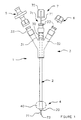
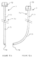
- FIG. 1 shows a catheter 1 consisting of a cylindrical body 2 in translucent plastic material, substantially flexible or rigid, integral with one of its ends of a head 3 forming connection means and comprising three independent entrances 30, 31 and 32.
- the cylindrical body 2 has, at the end opposite to that carrying the head 3, sealing means 4 consisting of a balloon 40 capable of elastically deform under the effect of pressure.
- the free end of the cylindrical body ends in a tapered profile 20 in the shape of a point (FIGS. 11, 12).
- connection head 3 is made of a rigid plastic which can be transparent or not and whose internal part is hollow so that each entry 30, 31 and 32 opens into channels in the body cylindrical 2.
- connection head 3 is in one piece and has a double Y fork profile, that is to say that the inlet 30 is carried by the same longitudinal axis as that of the cylindrical body 2, while the other two inputs 31 and 32 are offset laterally to be arranged respectively on each side of the inlet 30.
- the inputs 30, 31 and 32 are each secured to a connecting element 33 allowing the tight fixing, for example, of a valve 5 for the introduction of liquids, a plug 6 obstructing an inlet, and the installation of a series of surgical mandrels 7 whose profile varies depending on the case of the intervention.
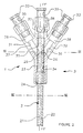
- Figures 2 to 4 show a first variant of the universal catheter 1 whose cylindrical body 2 is pierced, along its length, and along axes longitudinal offset from the main XX 'and YY' of two channels 21 and 22.
- the diameter of the main channel 21 is greater than that provided for the channel 22 and that the latter are carried by at least one main axis ZZ 'of the cylindrical body 2 ( Figure 4). Also, channels 21 and 22 are offset one compared to each other. In addition, the channel 21 is eccentric with respect to the diameter outside of the cylindrical body 2.
- the head 3 has an internal bore 34 which opens into each inlet 30, 31 and 32 via a bore 35, 36 and 37.
- Inputs 30, 31 and 32 each have a chamber 38 into which, on the one hand, each bore 35, 36 and 37, and on the other hand the connecting elements 33.
- the connecting elements 33 have an internal bore 39 which communicates with the chamber 38 of each inlet 30, 31 and 32 of the head 3.
- the head 3 is integral with the cylindrical body 2 in a sealed manner by means of a first ring 24 which is arranged around said body and opposite the inlet 30 in a shoulder of the bore 34 which is provided with a diameter greater than that latest.
- a second ring 23 is placed around the cylindrical body 2 in the extension of the first so as to cooperate with bores 34 and 35 of the head 3.
- the rings 23 and 24 are glued to the external profile of the body cylindrical 2 and on the inner periphery of bores 34 and 35 in order to make the head connection 3 secured to said body.
- the two rings 23 and 24 are provided with different outside diameters, while that their internal diameter is identical to cooperate coaxially around the cylindrical body 2.
- the cylindrical body 2 passes through the chamber 38 of the inlet 30 to allow the large diameter channel 21 to open into the bore 39 of the element link 33 corresponding.
- the main channel 21 opens outside the cylindrical body 2 according to the tapered profile 20 in the form of a point or conical.
- end 20 of the cylindrical body 2 has a conical profile which is focused on the main channel 21. The latter is offset from the outer diameter of the cylindrical body 2, which gives this particular profile to the end 20 ( Figures 11, 12).
- the end 20 has a conical profile which has an inclination of approximately 30 ° degrees.
- the conical profile of the end 20 is intended to come in line with the instruments or mandrels 7, the end of which is also conical.
- the balloon 40 is fixed on the cylindrical body 2 of the catheter to immediate proximity of the cone of the end 20, and more particularly at the level from the widest base of the cone, i.e. the one furthest from the tip of the catheter ( Figures 11, 12).
- the ring 23 and the cylindrical body 2 are pierced with a first through hole 25 allowing the bore 37 of the inlet 31 to communicate with the channel of large diameter 21.
- the inlet 31 cooperates with a sealed plug, not shown, allowing, by tightening of the latter on the threaded part of the inlet 31, to achieve sealing with the mandrel or the instrument introduced into the channel 21.
- the ring 23 and the cylindrical body 2 are drilled with another hole opening 26 located opposite the first 25 to allow the bore 36 to the input 32 to communicate with the smaller diameter channel 22.
- the latter arranged parallel to channel 21, is intended to open out at the level of the sealing means 4 to allow the balloon 40 to be inflated.
- the universal catheter 1 described above is of the three entry two type channels, that is to say that two inputs lead into the same channel.
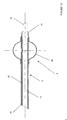
- the cylindrical body 2 comprises in addition to channels 21 and 22, another channel 27 carried by axes which are laterally offset from the main XX 'and YY 'of the cylindrical body and offset with respect to those carrying the channels 21 and 22.
- channels 22 are provided which are drilled on either side. of channel 27 between the latter and channel 21.
- channels 22 are carried by the same axis which is parallel to that XX 'of the cylindrical body 2, but arranged in a different vertical plane as shown in Figure 7.
- channels 21 and 27 are carried by the same axis ZZ 'of the body cylindrical 2 (figure 7).
- the cylindrical body 2 is integral with the head 3 described above provided with its three independent entrances 30, 31 and 32.
- the cylindrical body 2 is secured to the head 3 by means of the ring 24, as described above, while in this variant the outside diameter of the body 2 is glued directly into bore 35.
- the ring 24 is shorter in length than that described above. to define in the shoulder of the bore 34 a chamber 8 which is crossed by the cylindrical body 2.
- the longitudinal channel 10 is provided only on the side of the inlet 32, so that the external wall of the cylindrical body 2 is in sealed contact, on the one hand on the internal periphery of the bore 35, and on the other hand opposite the longitudinal channel 10 on the internal periphery of the bore 34 so that the bore 37 of the inlet 31 does not cannot communicate with room 8.
- the cylindrical body 2 is pierced with a first through hole 28 which allows communication between said bore 37 and channel 27.
- channels 21 and 27 open to the outside on the opposite side at head 3 and more particularly at the tip-shaped end tapered 20.
- cylindrical body 2 is drilled at the level of the chamber of holes opening 29 which communicate with the channels 22.
- the input 32 is connected by means of its bore 36, the longitudinal channel 10, the chamber 8, holes 29 and channels 22 with the balloon 40 which is disposed on the body cylindrical 2 opposite the head 3, in order to deform it elastically under a pressure effort.
- the catheter 1 described above and shown in Figures 5 to 7, has three inlets and three ways or channels compared to the previous one which had only two ways or channels.
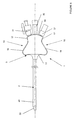
- Figures 8 to 10 show a third variant of the universal catheter 1 in that which relates to the profile of the connection head 3 on the cylindrical body 2.
- connection head 3 has a very ergonomic profile allowing the surgeon to hold catheter 1 securely between the fingers of one of his hands when different interventions.
- the head 3 has a slightly curved wall 14 receiving the three inputs independent 30, 31, 32.
- the wall 14 is arranged perpendicular to the body cylindrical 2 and is extended on each side of said body by a wall 15, 16 to inclined sides.
- Each wall 15, 16 has, near the entrances 31, 32, a inclined face 17 of short length which is directed towards the cylindrical body 2.
- Each inclined plane 17 is extended by another inclined plane 18 of inclination different and directed so as to move away from the cylindrical body 2.
- Each wall inclined 18 of the walls 15, 16 meets at the level of the cylindrical body 2 and at the opposite of the wall 14 by a wall 19 curved in the direction of said body.
- connection head 3 allows better grip on the part of the surgeon to perfectly introduce the cylindrical body 2 into the different operating sites.
- connection head 3 whose inputs 30, 31, 32 cooperate with the non-coaxial channels 21, 22 of the body cylindrical 2 as described in Figure 2 to 4.
- connection head 3 allows the input 30 to communicate with the channel 21, said main channel, while the input 32 cooperates with channel 22 for supply the balloon 40.
- the inlet 31 also cooperates with the channel 21 of the cylindrical body 2.
- the inlet 30 includes an internal bore 35 which is offset to come to cooperate opposite the channel 21, given that the latter is eccentric relative to the external diameter of the cylindrical body 2 ( Figure 4).
- connection head 3 it can be seen that the chambers 38 have been deleted so that each bore 35, 36, 37 of the inputs 30, 31, 32 leads directly into the non-coaxial channels of the body 2 and at the end of the head 3.
- connection head 3 the internal part of the connection head 3 is illustrated, the inputs 30, 31, 32 cooperate with the non-coaxial channels 21, 22, 27 of the body cylindrical 2 as described in Figures 5 to 7.
- connection head 3 allows the input 30 to communicate with the channel 21, while the inputs 31 and 32 cooperate respectively with the channel 27, said channel operator, for the passage of instruments and channels 22 for feeding the balloon 40.
- the inlet 31 has an internal bore 37 whose inclination allows communication with channel 27 via a hole drilled in across the cylindrical body 2.
- the inlet 32 has an internal bore 36 which is also inclined and turned a quarter turn around the axis of the cylindrical body 2 to come communicate through holes in channels 22. This position eliminates the chamber 8 and the longitudinal channel 10, shown in Figure 5.
- the head of connection 3 is made of injected plastic which comes directly fix at the time of molding around the cylindrical body 2, thus guaranteeing a perfect sealing of the head 3 on the body 2.
- the end of the cylindrical body 2 is secured to a balloon or balloon 40 whose external profile depends on the distance between the points of fixing said balloon to the body 2.
- the areas of attachment of the balloon 40 are brought together allowing the latter to present, when inflated, a very rounded profile like a tire, around the cylindrical body 2.
- the areas for fixing the balloon 40 are more distant than those shown above, which allows to define a volume of the balloon which is different when inflated.
- the balloon 40 provided at the end of the cylindrical body 2 of the catheter 1 makes it possible to sealing by coming to bear against the wall of the operating site, as we will see better later. Also, the balloon 40 makes it possible to carry out a support and a kind of ball joint facilitating the movements of the catheter 1 in the space of the operating site and prevents rejection outside the site.
- the mandrels 7 are constituted in each representation of a head 70 in plastic material secured to a metal rod 71 of small diameter.
- the mandrel 7a has at the end of its rod 71 a free end 72 performed along a hemispherical profile.
- the mandrel 7b comprises a rod 70 having a curved profile, but whose free end 72 is produced according to a hemispherical profile.
- the mandrel 7c comprises at the end of its rod 70 a free end 73 in the shape of a very tapered or conical point whose inclination is similar to that of the end 20 of the cylindrical body 2 in order to be housed in its extension ( Figure 11).
- the last mandrel 7d of the series has a free end 74 with a conical profile, but the end of which is slightly rounded.
- the conical profile of the end 74 comes in the extension of the conical end 20 of the body 2.
- Figure 15 illustrates a first example of examination using the universal catheter 1 comprising a head 3 with three inputs and two channels 21 and 22.
- the catheter 1 is inserted inside the uterus a of a patient P in order to carry out, for example, a test with methylene blue in order to check the permeability of the fallopian tubes b .
- the head 3, and more particularly the inlet 31, is secured to an associated tap 5 to a syringe 9 filled with a liquid consisting of methylene blue, while the inlet 30 is closed in a sealed manner by the head 70 of a mandrel 7.
- the inlet 32 is connected via a non-return valve to a source of air or pressurized liquid 11 to allow the balloon 40 to be inflated inside the uterus a in order to obstruct it. last and to make it waterproof during the introduction of methylene blue.
- the mandrels 7a or 7b are introduced via the inlet 30 which communicates with the same channel 21 as that of input 31 used for the introduction of blue methylene so that end 72 is housed in the operating site of the uterus a.
- the introduction of a mandrel 7a or 7b allows the mobilization of the uterus has for facilitate its examination during laparoscopy performed jointly.
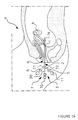
- Figure 16 shows another procedure using the universal catheter 1 to three inputs and two channels for a FERTILOSCOPY.
- This operation consists in making an incision in the vaginal pouch c under local anesthesia.
- This FERTILOSCOPY is performed using the universal catheter 1 associated with a mandrel 7 such as 7c which is introduced into the operating channel 27 of the cylindrical body 2.
- FERTILOSCOPY consists in the creation of an artificial ascites by serum which is injected through the universal catheter into the operating site to allow observation of the appendices under the most physiological conditions possible.
- catheter 1 with three inputs and three channels or channels, perform a FERTILOSCOPY by inserting surgical mandrels into the channel 27 of the cylindrical body, and in particular a grasping forceps stabilizing the pavilion, a FERTILOSCOPE allowing to realize independently a salpingoscopy.
- the same channel 27 allows biopsies, incision of hydrosalpinx before to make an operational decision.
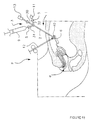
- Figure 17 shows another application for using the universal catheter 1 as a trocar during laparoscopy for salpingoscopy.
- the universal catheter 1 is introduced into the pavilion of a tube b which is raised by means of a clamp 12.
- the balloon 40 is inflated by means of a source of air or liquid under pressure 11 which is connected at the input 32 by means of a non-return valve 5.
- a mini endoscope 13 is introduced by the input 30 so that its optics are housed inside the pavilion to be examined. This mini endoscope is placed after the withdrawal of a mandrel 7c at end 73 which allows the skin of patient P to be pierced.
- a syringe 9 is disposed on the inlet 31 which has another tap 5 so fill the serum pavilion to facilitate optical examination.
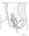
- Figure 18 illustrates a final application for using the universal catheter 1 to perform a salpingoscopy.
- the catheter used is a three entry three pathways, allowing, when introduced into the operating site, to bring through the operating channel 27 a clamp 41, while a mini endoscope 13 is arranged in the eccentric channel 21.
- the dimensions of the latter make it possible to inject a liquid around the mini endoscope 13 during the visit of the tube retained by the clamp.
- channels 21 and 27 are adapted to receive the rods 71 of the mandrels 7a, 7b, 7c, 7d, or of surgical instruments while allowing the injection of a liquid in the same channel.
- the universal catheter 1 when used as a trocar, replaces the liquid infiltration sheath which is compulsory when using mini optical endoscopes 13.
- the diameter of channel 21 makes it possible to receive any mini endoscope 13 whose external diameter does not exceed 4mm when the sheath or infiltration jacket is removed.
- cylindrical body 2 is made of a transparent plastic material allowing control of the descent of the optics 13 inside the catheter 1.
- the universal catheter according to the present invention replaces sheaths or sleeves necessary for the use of mini endoscopes.
Abstract
Description
La présente invention est relative à un cathéter universel à usage unique permettant plus particulièrement l'introduction dans le corps humain au niveau du site opératoire, soit des mandrins chirurgicaux, soit l'injection de liquide tel que du sérum ou du bleu de méthylène pour réaliser différents tests préopératoires et peropératoires.The present invention relates to a universal disposable catheter allowing more particularly the introduction into the human body at the level of surgical site, either surgical mandrels, or the injection of liquid such as serum or methylene blue to perform various preoperative tests and Intraoperative.
On entend par cathéter universel un cathéter/trocart ayant la fonction d'un outil pour la perforation des parois et la fonction d'un cathéter pour l'introduction dans le site opératoire, soit de produits liquides, soit une gamme de mandrins chirurgicaux ou autres instruments, soit les deux en même temps.By universal catheter is meant a catheter / trocar having the function of a tool for the perforation of the walls and the function of a catheter for the introduction into the operating site, either of liquid products or a range of mandrels surgical or other instruments, both at the same time.
On connaít des cathéters de ce genre qui comportent un corps cylindrique solidaire à l'une de ses extrémités d'une tête munie de deux voies d'accès ou entrées, tandis que l'autre extrémité est pourvue d'un ballon susceptible de se déformer élastiquement sous l'effet d'une pression voir par exemple le document WO92/17236We know catheters of this kind which have a cylindrical body secured at one of its ends to a head provided with two access routes or entrances, while the other end is provided with a balloon capable of elastically deform under the effect of pressure see for example document WO92 / 17236
Ce genre de cathéter permet de réaliser certains tests ou opérations, mais ne peut pas simultanément recevoir des mandrins chirurgicaux, et l'injection de liquides ou le passage d'un mini endoscope du fait que les canaux ménagés dans le corps cylindrique sont coaxiaux entre eux et centrés par rapport aux axes principaux dudit corps.This type of catheter allows certain tests or operations to be carried out, but does not cannot simultaneously receive surgical mandrels, and the injection of liquids or the passage of a mini endoscope because the channels formed in the cylindrical body are coaxial with each other and centered with respect to the axes principal of said body.
En effet, un premier canal, centré autour des axes principaux du corps, permet la mise en place d'un mini endoscope ou le passage d'un liquide ou la mise en place d'un mandrin chirurgical. L'ensemble de ses éléments étant introduit séparément et de manière indépendante. Le second canal coaxial au premier est prévu uniquement pour déformer élastiquement le ballon.Indeed, a first channel, centered around the main axes of the body, allows the placement of a mini endoscope or passage of a liquid or placement of a surgical mandrel. All of its elements being introduced separately and independently. The second coaxial channel to the first is planned only to elastically deform the balloon.
On connaít également d'après le brevet US 5 437 637 un cathéter comportant un corps cylindrique souple percé dans sa partie interne de plusieurs canaux non coaxiaux pour le passage de raidisseurs, d'instruments et/ou de liquides. Ce cathéter comprend sur sa périphérie externe un ballonnet qui peut se dilater sous l'effet d'une pression.Also known from US Patent 5,437,637 a catheter having a flexible cylindrical body pierced in its internal part with several channels not coaxial for the passage of stiffeners, instruments and / or liquids. This catheter includes a balloon on its outer periphery which can expand under the effect of pressure.
On remarque que ce genre de cathéter ne permet pas, du fait de sa souplesse, d'être utilisé comme un trocart afin de perforer des parois. De plus, les moyens de connexion permettent l'introduction dans chaque canal non coaxial, soit d'instruments, soit de liquides, mais ne permettent pas au chirurgien une tenue du cathéter pour pouvoir l'utiliser comme un outil.We note that this kind of catheter does not allow, because of its flexibility, to be used as a trocar in order to perforate walls. In addition, the means of connection allow introduction into each non-coaxial channel, i.e. instruments, or liquids, but do not allow the surgeon to hold the catheter to be able to use it as a tool.
C'est à ces inconvénients qu'entend plus particulièrement remédier la présente
invention, défini par les revendications 1 à 33. It is to these drawbacks that the present present intends more particularly to remedy.
invention, defined by
La description qui va suivre en regard des dessins annexés, donnés à titre
d'exemples non limitatifs, permettra de mieux comprendre l'invention, les
caractéristiques qu'elle présente et les avantages qu'elle est susceptible de
procurer:
On a montré en figure 1 un cathéter 1 constitué d'un corps cylindrique 2 en
matière plastique translucide sensiblement souple ou rigide solidaire à l'une de
ses extrémités d'une tête 3 formant des moyens de connexion et comportant trois
entrées indépendantes 30, 31 et 32.FIG. 1 shows a
Le corps cylindrique 2 présente à l'extrémité opposée à celle portant la tête 3, des
moyens d'étanchéité 4 constitués d'un ballon ou ballonnet 40 susceptible de se
déformer élastiquement sous l'effet d'une pression.The
A proximité du ballon 40, l'extrémité libre du corps cylindrique se termine par un
profil effilé 20 en forme de pointe (figures 11, 12). Near the
La tête de connexion 3 est réalisée en une matière plastique rigide qui peut être
transparente ou non et dont la partie interne est creuse de manière que chaque
entrée 30, 31 et 32 débouche dans des canaux ménagés dans le corps
cylindrique 2.The
La tête de connexion 3 est monobloc et présente un profil de fourche en double Y,
c'est à dire que l'entrée 30 est portée par le même axe longitudinal que celui du
corps cylindrique 2, tandis que les deux autres entrées 31 et 32 sont décalées
latéralement pour être disposées respectivement de chaque côté de l'entrée 30.The
Les entrées 30, 31 et 32 sont solidaires chacune d'un élément de liaison 33
permettant la fixation étanche, par exemple, d'une vanne 5 pour l'introduction de
liquides, d'un bouchon 6 obstruant une entrée, et la mise en place d'une série de
mandrins chirurgicaux 7 dont le profil varient suivant le cas de l'intervention.The
En figures 2 à 4 on a représenté une première variante du cathéter universel 1
dont le corps cylindrique 2 est percé, sur sa longueur, et suivant des axes
longitudinaux décalés par rapport à ceux principaux XX' et YY' de deux canaux 21
et 22.Figures 2 to 4 show a first variant of the
On note que le diamètre du canal principal 21 est supérieur à celui prévu pour le
canal 22 et que ces derniers sont portés par au moins un axe principal ZZ' du
corps cylindrique 2 (figure 4). Egalement, les canaux 21 et 22 sont décalés l'un
par rapport à l'autre. De plus, le canal 21 est excentré par rapport au diamètre
extérieur du corps cylindrique 2.It is noted that the diameter of the
La tête 3 présente un alésage interne 34 qui débouche dans chaque entrée 30, 31
et 32 par l'intermédiaire d'un alésage 35, 36 et 37. Les entrées 30, 31 et 32
comportent chacune une chambre 38 dans laquelle débouche, d'une part chaque
alésage 35, 36 et 37, et d'autre part les éléments de liaison 33.The
Les éléments de liaison 33 présentent un alésage interne 39 qui communique
avec la chambre 38 de chaque entrée 30, 31 et 32 de la tête 3.The
La tête 3 est solidaire du corps cylindrique 2 de manière étanche au moyen d'une
première bague 24 qui est disposée autour dudit corps et à l'opposé de l'entrée
30 dans un épaulement de l'alésage 34 qui est prévu d'un diamètre supérieur à ce
dernier.The
Une seconde bague 23 est placée autour du corps cylindrique 2 dans le
prolongement de la première de manière à coopérer avec les alésages 34 et 35
de la tête 3. Les bagues 23 et 24 sont collées sur le profil externe du corps
cylindrique 2 et sur le pourtour interne des alésages 34 et 35 afin de rendre la tête
de connexion 3 solidaire dudit corps.A
Les deux bagues 23 et 24 sont prévues de diamètres extérieurs différents, tandis
que leur diamètre interne est identique pour coopérer coaxialement autour du
corps cylindrique 2. The two
Le corps cylindrique 2 traverse la chambre 38 de l'entrée 30 pour permettre au
canal de grand diamètre 21 de déboucher dans l'alésage 39 de l'élément de
liaison 33 correspondant.The
A l'opposé, le canal principal 21 débouche à l'extérieur du corps cylindrique 2
suivant le profil effilé 20 en forme de pointe ou conique.In contrast, the
On remarque que l'extrémité 20 du corps cylindrique 2 présente un profil conique
qui est axé sur le canal principal 21. Ce dernier est excentré par rapport au
diamètre extérieur du corps cylindrique 2, ce qui donne ce profil particulier à
l'extrémité 20 (figures 11, 12).Note that the
Ainsi, l'extrémité 20 présente un profil conique qui est d'une inclinaison d'environ
30° degrés.Thus, the
Le profil conique de l'extrémité 20 est prévu pour venir dans le prolongement des
instruments ou mandrins 7 dont l'extrémité est également conique.The conical profile of the
On constate que le ballon 40 est fixé sur le corps cylindrique 2 du cathéter à
proximité immédiate du cône de l'extrémité 20, et plus particulièrement au niveau
de la base la plus large du cône, c'est à dire celle la plus éloignée du bout du
cathéter (figures 11, 12).It can be seen that the
La bague 23 et le corps cylindrique 2 sont percés d'un premier trou débouchant
25 permettant à l'alésage 37 de l'entrée 31 de communiquer avec le canal de
grand diamètre 21.The
L'entrée 31 coopère avec un bouchon étanche, non représenté, permettant, par
serrage de ce dernier sur la partie filetée de l'entrée 31, de réaliser l'étanchéité
avec le mandrin ou l'instrument introduit dans le canal 21.The
Ainsi, on remarque que deux entrées 30 et 31 débouchent dans le même canal 21
ménagé dans la partie interne du corps cylindrique 2.Thus, we notice that two
De même, la bague 23 et le corps cylindrique 2 sont percés d'un autre trou
débouchant 26 situé à l'opposé du premier 25 pour permettre à l'alésage 36 de
l'entrée 32 de communiquer avec le canal de plus petit diamètre 22. Ce dernier,
disposé parallèlement au canal 21, est prévu pour déboucher au niveau des
moyens d'étanchéité 4 pour permettre de gonfler le ballon 40.Similarly, the
On note que le cathéter universel 1 décrit ci-dessus est du type trois entrées deux
voies, c'est à dire que deux entrées débouchent dans le même canal.Note that the
En figures 5 à 7 on a montré une seconde variante du cathéter universel 1 dont le
corps cylindrique 2 comporte en plus des canaux 21 et 22, un autre canal 27 porté
par des axes qui sont décalés latéralement par rapport à ceux principaux XX' et
YY' du corps cylindrique et décalés par rapport à ceux portant les canaux 21 et
22. In FIGS. 5 to 7, a second variant of the
Dans cette variante il est prévu deux canaux 22 qui sont percés de part et d'autre
du canal 27 entre ce dernier et le canal 21. On remarque que les canaux 22 sont
portés par un même axe qui est parallèle à celui XX' du corps cylindrique 2, mais
disposé dans un plan vertical différent comme montré en figure 7.In this variant, two
On constate que les canaux 21 et 27 sont portés par le même axe ZZ' du corps
cylindrique 2 (figure 7).It can be seen that the
Le corps cylindrique 2 est solidaire de la tête 3 décrite ci-dessus munie de ses
trois entrées indépendantes 30, 31 et 32.The
On remarque que les entrées 30, 31, 32 sont solidaires de l'élément de liaison 33,
afin de délimiter la chambre 38.It will be noted that the
Le corps cylindrique 2 est solidaire de la tête 3 au moyen de la bague 24, comme
décrit précédemment, tandis que dans cette variante le diamètre extérieur du
corps 2 est collé directement dans l'alésage 35.The
On note que la bague 24 est de longueur inférieure à celle décrite précédemment
pour délimiter dans l'épaulement de l'alésage 34 une chambre 8 qui est traversée
par le corps cylindrique 2.It should be noted that the
En effet, le retrait de la bague 23 permet de réaliser un canal longitudinal 10
(figures 5 et 6) ménagé dans l'alésage 34 de façon à faire communiquer la
chambre 8 pour alimenter les canaux 22 pour le gonflage du ballon 40.Indeed, the withdrawal of the
Le canal longitudinal 10 est prévu uniquement du côté de l'entrée 32, de manière
que la paroi externe du corps cylindrique 2 soit en contact étanche, d'une part sur
le pourtour interne de l'alésage 35, et d'autre part à l'opposé du canal longitudinal
10 sur le pourtour interne de l'alésage 34 pour que l'alésage 37 de l'entrée 31 ne
puisse pas communiquer avec la chambre 8.The
Au niveau de l'alésage 37 de l'entrée 31 le corps cylindrique 2 est percé d'un
premier trou débouchant 28 qui permet la communication entre ledit alésage 37 et
le canal 27.At the
Dans cette variante les canaux 21 et 27 débouchent à l'extérieur du côté opposée
à la tête 3 et plus particulièrement au niveau de l'extrémité en forme de pointe
effilée 20.In this variant the
On note que le corps cylindrique 2 est percé au niveau de la chambre de trous
débouchant 29 qui communiquent avec les canaux 22. Ainsi, l'entrée 32 est reliée
par l'intermédiaire de son alésage 36, du canal longitudinal 10, de la chambre 8,
des trous 29 et des canaux 22 avec le ballon 40 qui est disposé sur le corps
cylindrique 2 à l'opposé de la tête 3, afin de le déformer élastiquement sous un
effort de pression.It is noted that the
Le cathéter 1 décrit ci-dessus et montré en figures 5 à 7, comporte trois entrées et
trois voies ou canaux par rapport au précèdent qui ne comportait que deux voies
ou canaux. The
En figures 8 à 10 on a montré une troisième variante du cathéter universel 1 en ce
qui concerne le profil de la tête de connexion 3 sur le corps cylindrique 2.Figures 8 to 10 show a third variant of the
La tête de connexion 3 présente un profil très ergonomique permettant au
chirurgien de bien maintenir le cathéter 1 entre les doigts d'une de ses mains lors
des différentes interventions.The
La tête 3 comporte une paroi 14 légèrement bombée recevant les trois entrées
indépendantes 30, 31, 32. La paroi 14 est disposée perpendiculairement au corps
cylindrique 2 et se prolonge de chaque côté dudit corps par une paroi 15, 16 à
pans inclinés. Chaque paroi 15, 16 présente à proximité des entrées 31, 32 un
pan incliné 17 de faible longueur qui est dirigé en direction du corps cylindrique 2.
Chaque pan incliné 17 se prolonge par un autre pan incliné 18 d'inclinaison
différente et dirigé de manière à s'éloigner du corps cylindrique 2. Chaque paroi
inclinée 18 des parois 15, 16 se réunie au niveau du corps cylindrique 2 et à
l'opposé de la paroi 14 par une paroi 19 incurvée en direction dudit corps.The
Ainsi, le profil de la tête de connexion 3 permet une meilleur préhension de la part
du chirurgien pour parfaitement introduire le corps cylindrique 2 dans les différents
sites opératoires.Thus, the profile of the
En figure 9 on a représenté la partie interne de la tête de connexion 3 dont les
entrées 30, 31, 32 coopèrent avec les canaux non coaxiaux 21, 22 du corps
cylindrique 2 comme cela a été décrit en figure 2 à 4.In Figure 9 there is shown the internal part of the
Ainsi, la tête de connexion 3 permet à l'entrée 30 de communiquer avec le canal
21, dit canal principal, tandis que l'entrée 32 coopère avec le canal 22 pour
alimenter le ballon 40.Thus, the
On note que l'entrée 31 coopère également avec le canal 21 du corps cylindrique
2. On remarque que l'entrée 30 comprend un alésage interne 35 qui est désaxé
pour venir coopérer en face du canal 21, étant donné que ce dernier est excentré
par rapport au diamètre externe du corps cylindrique 2 (figure 4).Note that the
Dans cette réalisation de la tête de connexion 3, on constate que les chambres 38
on été supprimées de manière que chaque alésage 35, 36, 37 des entrées 30, 31,
32 débouche directement dans les canaux non coaxiaux du corps 2 et à
l'extrémité de la tête 3.In this embodiment of the
En figure 10 on a illustré la partie interne de la tête de connexion 3 dont les
entrées 30, 31, 32 coopèrent avec les canaux non coaxiaux 21, 22, 27 du corps
cylindrique 2 comme cela est décrit en figures 5 à 7.In FIG. 10, the internal part of the
Ainsi, la tête de connexion 3 permet à l'entrée 30 de communiquer avec le canal
21, tandis que les entrées 31 et 32 coopèrent respectivement avec le canal 27, dit
canal opérateur, pour le passage d'instruments et les canaux 22 pour
l'alimentation du ballon 40. Thus, the
On remarque que l'entrée 31 présente un alésage interne 37 dont l'inclinaison
permet la communication avec le canal 27 par l'intermédiaire d'un trou percé au
travers du corps cylindrique 2.Note that the
Par contre, l'entrée 32 présente un alésage interne 36 qui est également incliné et
tourné d'un quart de tour autour de l'axe du corps cylindrique 2 pour venir
communiquer par l'intermédiaire de trous dans les canaux 22. Cette position
permet de supprimer la chambre 8 et le canal longitudinal 10, montré en figure 5.On the other hand, the
Dans les solutions décrites ci-dessus et représentées en figure 9 et 10, la tête de
connexion 3 est réalisée en matière plastique injectée qui vient directement se
fixer au moment du moulage autour du corps cylindrique 2, garantissant ainsi une
parfaite étanchéité de la tête 3 sur le corps 2.In the solutions described above and represented in FIGS. 9 and 10, the head of
En figure 11, l'extrémité du corps cylindrique 2 est solidaire d'un ballon ou
ballonnet 40 dont le profil extérieur dépend de la distance entre les points de
fixation dudit ballonnet sur le corps 2.In FIG. 11, the end of the
Ainsi, on note que les zones de fixation du ballonnet 40 sont rapprochées
permettant à ce dernier de présenter, lorsqu'il et gonflé, un profil très arrondi
comme un pneu, autour du corps cylindrique 2.Thus, it is noted that the areas of attachment of the
En figure 12, les zones de fixation du ballonnet 40 sont plus éloignées que celles
montrées précédemment, ce qui permet de définir un volume du ballonnet qui est
différent lorsqu'il est gonflé.In FIG. 12, the areas for fixing the
Le ballonnet 40 prévu à l'extrémité du corps cylindrique 2 du cathéter 1 permet de
réaliser une étanchéité en venant prendre appui contre la paroi du site opératoire,
comme on le verra mieux plus loin. Également, le ballonnet 40 permet de réaliser
un appui et une sorte de rotule facilitant les déplacements du cathéter 1 dans
l'espace du site opératoire et empêche le rejet hors du site.The
En figures 13a, 13b et 14a, 14b on a montré une série 7a, 7b, 7c, 7d
d'instruments chirurgicaux, ou mandrins 7, permettant la réalisation des examens
illustrés en figures 15 et 11.In Figures 13a, 13b and 14a, 14b we have shown a
Les mandrins 7 sont constitués dans chaque représentation d'une tête 70 en
matière plastique solidaire d'une tige métallique 71 de faible diamètre.The
On remarque que seule l'extrémité libre opposée à la tête 70 varie dans sa forme
géométrique et sa matière pour permettre différent type examen.Note that only the free end opposite the
En figure 13a le mandrin 7a présente au bout de sa tige 71 une extrémité libre 72
réalisée suivant un profil hémisphérique.In Figure 13a the
En figure 13b le mandrin 7b comporte une tige 70 présentant un profil courbe,
mais dont l'extrémité libre 72 est réalisée suivant un profil hémisphérique.In FIG. 13b, the mandrel 7b comprises a
En figure 14a le mandrin 7c comprend au bout de sa tige 70 une extrémité libre
73 en forme de pointe très effilée ou conique dont l'inclinaison est semblable à
celle de l'extrémité 20 du corps cylindrique 2 pour venir se loger dans son
prolongement (figure 11).In FIG. 14a the
Enfin, en figure 14b le dernier mandrin 7d de la série comporte une extrémité libre
74 à profil conique, mais dont le bout est légèrement arrondi. De même que
précédemment, le profil conique de l'extrémité 74 vient dans le prolongement de
l'extrémité conique 20 du corps 2.Finally, in Figure 14b the
Le cathéter universel 1 décrit précédemment et ses mandrins 7a, 7b, 7c, 7d, sont conçus pour effectuer un ensemble de procédures réunies sous l'appellation FERTILOSCOPY et qui consiste en plusieurs étapes permettant :
- une appréciation de l'état utérin,
- une appréciation de la perméabilité tubaire,
- une appréciation de l'environnement péri tubo ovarien,
- une visualisation sans pareil de la partie distale des trompes et des ovaires,
- une appréciation de la qualité tubaire par la salpingoscopie associée.
- an appreciation of the uterine condition,
- an assessment of tubal permeability,
- an appreciation of the peri tubo ovarian environment,
- unparalleled visualization of the distal part of the fallopian tubes and ovaries,
- an appreciation of the tubal quality by the associated salpingoscopy.
La figure 15 illustre un premier exemple d'examen au moyen du cathéter universel
1 comportant une tête 3 à trois entrées et deux canaux 21 et 22.Figure 15 illustrates a first example of examination using the
Le cathéter 1 est introduit à l'intérieur de l'utérus a d'une patiente P afin de
réaliser, par exemple, un test au bleu de méthylène afin de vérifier la perméabilité
des trompes b.The
La tête 3, et plus particulièrement l'entrée 31, est solidaire d'un robinet 5 associé
à une seringue 9 remplie d'un liquide constitué de bleu de méthylène, tandis que
l'entrée 30 est fermée de manière étanche par la tête 70 d'un mandrin 7.The
L'entrée 32 est reliée par l'intermédiaire d'une vanne anti-retour à une source d'air
ou de liquide sous pression 11 pour permettre de gonfler le ballon 40 à l'intérieur
de l'utérus a afin d'obstruer ce dernier et de le rendre étanche lors de
l'introduction du bleu de méthylène.The
Les mandrins 7a ou 7b sont introduits par l'entrée 30 qui communique avec le
même canal 21 que celui de l'entrée 31 utilisé pour l'introduction du bleu de
méthylène afin que l'extrémité 72 soit logée dans le site opératoire de l'utérus a.
L'introduction d'un mandrin 7a ou 7b permet la mobilisation de l'utérus a pour
faciliter son examen lors de la coelioscopie effectuée conjointement.The
La figure 16 montre une autre intervention au moyen du cathéter universel 1 à
trois entrées et deux canaux pour une FERTILOSCOPY.Figure 16 shows another procedure using the
Cette opération consiste à réaliser une incision du cul de sac vaginal c sous
anesthésie locale. Cette FERTILOSCOPY est réalisée à l'aide du cathéter
universel 1 associé avec un mandrin 7 tel que 7c qui est introduit dans le canal
opératoire 27 du corps cylindrique 2. This operation consists in making an incision in the vaginal pouch c under local anesthesia. This FERTILOSCOPY is performed using the
La FERTILOSCOPY consiste à la création d'une ascite artificielle par du sérum qui est injecté au moyen du cathéter universel dans le site opératoire pour permettre l'observation des annexes dans les conditions les plus physiologiques possibles.FERTILOSCOPY consists in the creation of an artificial ascites by serum which is injected through the universal catheter into the operating site to allow observation of the appendices under the most physiological conditions possible.
On peut également à l'aide du cathéter 1 à trois entrées et trois voies ou canaux,
réaliser une FERTILOSCOPY en introduisant des mandrins chirurgicaux dans le
canal 27 du corps cylindrique, et notamment une pince à préhension stabilisant le
pavillon, un FERTILOSCOPE permettant de réaliser de manière indépendante
une salpingoscopie.It is also possible using the
Le même canal 27 permet de réaliser des biopsies, incision d'hydrosalpinx avant
de prendre une décision opératoire.The
La figure 17 représente une autre application d'utilisation du cathéter universel 1
comme trocart au cours d'une coelioscopie pour une salpingoscopie.Figure 17 shows another application for using the
Le cathéter universel 1 est introduit dans le pavillon d'une trompe b qui est
soulevée par l'intermédiaire d'une pince 12. Le ballon 40 est gonflé au moyen
d'une source d'air ou de liquide sous pression 11 qui est raccordée à l'entrée 32
par l'intermédiaire d'une vanne anti-retour 5. Un mini endoscope 13 est introduit
par l'entrée 30 de manière que son optique soit logée à l'intérieur du pavillon à
ausculté. Ce mini endoscope est placé après le retrait d'un mandrin 7c à extrémité
73 qui permet de percer la peau de la patiente P.The
Une seringue 9 est disposée sur l'entrée 31 qui comporte un autre robinet 5 afin
de remplir le pavillon de sérum facilitant l'examen optique.A
Après avoir retiré le mini endoscope 13, la salpingotomie peut être réalisée si
nécessaire en s'aidant du ballon 40.After removing the
La figure 18 illustre une dernière application d'utilisation du cathéter universel 1
pour réaliser une salpingoscopie. Le cathéter utilisé est un trois entrées trois
voies, permettant, lorsqu'il est introduit dans le site opératoire, d'amener par le
canal opérateur 27 une pince 41, tandis qu'un mini endoscope 13 est disposé
dans le canal excentré 21. Les dimensions de ce dernier permettent d'injecter un
liquide autour du mini endoscope 13 pendant la visite de la trompe retenue par la
pince.Figure 18 illustrates a final application for using the
On remarque que les diamètres des canaux 21 et 27 sont adaptés pour recevoir
les tiges 71 des mandrins 7a, 7b, 7c, 7d,ou d'instruments chirurgicaux tout en
permettant l'injection d'un liquide dans le même canal.Note that the diameters of
On constate que le cathéter universel 1, lorsqu'il est utilisé en trocart, remplace la
gaine d'infiltration de liquide qui est obligatoire lors de l'utilisation des mini
endoscopes optiques 13. En outre, le diamètre du canal 21 permet de recevoir
tout mini endoscope 13 dont le diamètre extérieur n'excède pas 4mm lorsque la
gaine ou chemise d'infiltration est retirée. It can be seen that the
De plus, le corps cylindrique 2 est réalisé dans une matière plastique transparente
permettant le contrôle de la descente de l'optique 13 à l'intérieur du cathéter 1.In addition, the
On remarque que le cathéter universel suivant la présente invention, se substitue aux gaines ou chemises nécessaires à l'usage des mini endoscopes.It is noted that the universal catheter according to the present invention replaces sheaths or sleeves necessary for the use of mini endoscopes.
Enfin on remarque que le cathéter universel 1 est plus couramment utilisé dans le
domaine gynécologique pour réaliser l'ensemble des examens effectués à ce jour.Finally we note that the
Claims (23)
- Multipurpose catheter intended to permit various interventions, comprising a cylindrical body (2) of small diameter which has, at one of its ends, connection means (3) which communicate with non-coaxial channels (21, 22, 27) formed in the inner part of the said cylindrical body (2) in such a way that one of the channels (22) supplies, to the end remote from that bearing the connection means, a balloon (40) which is able to deform elastically, while two other channels (21, 27) permit introduction either of liquid or of a range of surgical mandrins (7), or both simultaneously, at the operating site, characterized in that the connection means consist of a monobloc head (3) made of rigid plastic material which can be injection-molded to attach itself in a sealed manner around the cylindrical body (2), the said head (3) including a bulged wall (14) provided with three independent inlets (30, 31, 32) which communicate with the non-coaxial channels (21, 22, 27) via bores (35, 36, 37), two walls (15, 16) with inclined surfaces continuing the wall (14) on each side of the cylindrical body (2), the said walls (15, 16) each having opposite surfaces (17, 18) of different inclination, and a wall (19) of inwardly curved profile connecting the surfaces (18) of each wall (15, 16) in the area of the cylindrical body (2), in such a way that the head (3) has a general ergonomic external profile facilitating the gripping of the catheter.
- Multipurpose catheter according to Claim 1, characterized in that each wall (15, 16) has, in proximity to the independent inlets (31, 32), an inclined surface (17) of short length which is oriented in the direction of the cylindrical body (2), while each surface (17) is continued by another inclined surface (18) which is oriented away from the cylindrical body (2) to join up with the inwardly curved wall (19).
- Multipurpose catheter according to Claim 1, characterized in that the cylindrical body (2) has, remote from the monobloc head (3), an end (2) with a conical profile.
- Multipurpose catheter according to Claim 3, characterized in that the conical profile of the end (20) of the cylindrical body (2) has its axis on the main channel (21).
- Multipurpose catheter according to Claim 3, characterized in that the main channel (21) is eccentric in relation to the external diameter of the cylindrical body (2).
- Multipurpose catheter according to Claim 3, characterized in that the balloon (40) is fixed on the cylindrical body (2) in immediate proximity to the cone of the end (20) and more particularly at the widest base of the cone, that is to say the one furthest from the end of the catheter (1).
- Multipurpose catheter according to Claim 1, characterized in that the connection means consist of a head (3) made of rigid plastic material and equipped with three independent inlets (30, 31, 32) which each open into an internal bore (34) via bores (35, 36, 37), the said bores (34, 35) being provided to receive through sealed means (23, 24) the external longitudinal profile of the cylindrical body (2) such that the said bores (35, 36, 37) of each independent inlet communicate via holes (25, 26, 28, 29) passing through the cylindrical body (2) and/or the sealed means (23, 24) with the non-coaxial channels (21, 22, 27) so that the channels (21, 27) permit introduction either of liquid products or of a range of surgical mandrins (7) and/or other instruments (13, 41), or both simultaneously at the different operating sites.
- Multipurpose catheter according to Claim 7, characterized in that the sealed means consist of a first ring (24) which is arranged around the cylindrical body (2) opposite the inlet (30) in a shoulder of the bore (34), and a second ring (23) which is placed around the said cylindrical body (2) in the continuation of the first, in such a way as to cooperate with the bores (34, 35) of the head (3).
- Multipurpose catheter according to Claim 7, characterized in that the sealed means consist of a ring (24) which is arranged around the cylindrical body (2) opposite the inlet (30) in a shoulder of the bore (34), while the external diameter of the body (2) is directly fixed in the bore (35) of the head (3).
- Multipurpose catheter according to Claim 81 [sic], characterized in that the rings (23, 24) are bonded on the external profile of the cylindrical body (2) and on the internal periphery of the bores (34, 35) in order to make the head (3) integral with the said body.
- Multipurpose catheter according to Claim 9, characterized in that the ring (24) has a length which is defined in order to delimit, in the shoulder of the bore (34), a chamber (8) which communicates with the bore (36) of the inlet (32) of the head (3) via a space (10).
- Multipurpose catheter according to Claim 11, characterized in that the space (10) is provided solely on the inlet side (32) of the head (3), while the outer wall of the cylindrical body (2) is in tight contact on the one hand with the internal periphery of the bore (35) and, on the other hand, opposite the space (10), with the internal periphery of the bore (34).
- Multipurpose catheter according to either of Claims 1 and 7, characterized in that the cylindrical body (2) has two non-coaxial channels (21, 22) of different diameters which are offset in relation to each other and laterally in relation to the main axes (XX', YY') of the said body, in such a way that the first channel (21) communicates with two inlets (30, 31) of the head (3), while the second channel cooperates with the third inlet (32) for supplying the sealing means (4).
- Multipurpose catheter according to either of Claims 1 and 7, characterized in that the cylindrical body (2) has at least three non-coaxial channels (21, 22, 27) of different diameters which are offset in relation to each other and laterally in relation to the main axes (XX', YY') of the said body, in such a way that the first channel (21) of greater diameter communicates with the first inlet (30) of the head (3), the second channel (22) with the third inlet (32) of the head (3) for supplying the sealing means (4), and the third channel (27) with the second inlet (31) for emerging from the body (2) at the same level as the first channel (21).
- Multipurpose catheter according to either of Claims 1 and 7, characterized in that the cylindrical body (2) has a hole (25, 28) to permit communication between the channel (21, 27) and the bore (37) of the inlet (31).
- Multipurpose catheter according to either of Claims 1 and 7, characterized in that the cylindrical body (2) has a hole (26) permitting communication between the channel (22) and the bore (36) of the inlet (32).
- Multipurpose catheter according to either of Claims 1 and 7, characterized in that the cylindrical body (2) has two channels (22) which communicate via holes (29) in the chamber (8) connected to a space (10) in order to open into the bore (36) of the second inlet (32) of the head (3) in order to supply the sealed means (4).
- Multipurpose catheter according to either of Claims 1 and 7, characterized in that the surgical mandrins (7a, 7b, 7c, 7d) include a head (70) integral with a rod (71) whose free end (72, 73, 74) varies in its geometric shape and its material.
- Multipurpose catheter according to Claim 18, characterized in that the mandrin (7a) has a free end (72) designed with a hemispherical profile.
- Multipurpose catheter according to Claim 18, characterized in that the mandrin (7b) has a rod (71) of curved profile whose free end (72) is designed with a hemispherical profile.
- Multipurpose catheter according to either of Claims 1 and 7, characterized in that the cylindrical body (2) is rigid.
- Multipurpose catheter according to either of Claims 1 and 7, characterized in that the cylindrical body (2) is flexible.
- Multipurpose catheter according to either of Claims 1 and 7, characterized in that the cylindrical body (2) is transparent.
Applications Claiming Priority (3)
| Application Number | Priority Date | Filing Date | Title |
|---|---|---|---|
| FR9713988 | 1997-10-31 | ||
| FR9713988A FR2770409B1 (en) | 1997-10-31 | 1997-10-31 | UNIVERSAL CATHETER |
| PCT/FR1998/002119 WO1999022800A2 (en) | 1997-10-31 | 1998-10-05 | Multipurpose catheter |
Publications (2)
| Publication Number | Publication Date |
|---|---|
| EP1027091A2 EP1027091A2 (en) | 2000-08-16 |
| EP1027091B1 true EP1027091B1 (en) | 2004-02-11 |
Family
ID=9513129
Family Applications (1)
| Application Number | Title | Priority Date | Filing Date |
|---|---|---|---|
| EP98947598A Expired - Lifetime EP1027091B1 (en) | 1997-10-31 | 1998-10-05 | Multipurpose catheter |
Country Status (12)
| Country | Link |
|---|---|
| US (1) | US6689096B1 (en) |
| EP (1) | EP1027091B1 (en) |
| JP (2) | JP4745497B2 (en) |
| AT (1) | ATE259252T1 (en) |
| AU (1) | AU742003B2 (en) |
| CA (1) | CA2307735C (en) |
| DE (1) | DE69821638T2 (en) |
| DK (1) | DK1027091T3 (en) |
| ES (1) | ES2216314T3 (en) |
| FR (1) | FR2770409B1 (en) |
| PT (1) | PT1027091E (en) |
| WO (1) | WO1999022800A2 (en) |
Cited By (1)
| Publication number | Priority date | Publication date | Assignee | Title |
|---|---|---|---|---|
| CN109966602A (en) * | 2019-03-04 | 2019-07-05 | 赵寒英 | A kind of paediatrics ear chemical sprayer |
Families Citing this family (110)
| Publication number | Priority date | Publication date | Assignee | Title |
|---|---|---|---|---|
| DE10105592A1 (en) | 2001-02-06 | 2002-08-08 | Achim Goepferich | Placeholder for drug release in the frontal sinus |
| US6994706B2 (en) | 2001-08-13 | 2006-02-07 | Minnesota Medical Physics, Llc | Apparatus and method for treatment of benign prostatic hyperplasia |
| US8317816B2 (en) | 2002-09-30 | 2012-11-27 | Acclarent, Inc. | Balloon catheters and methods for treating paranasal sinuses |
| US7918817B2 (en) * | 2002-10-31 | 2011-04-05 | Medical Components, Inc. | Splittable multiple catheter assembly |
| US7261708B2 (en) * | 2002-10-31 | 2007-08-28 | Medical Components, Inc. | Removable catheter hub |
| US7713260B2 (en) * | 2003-09-11 | 2010-05-11 | Cook Incorporated | Catheter having an overmolded hub |
| US7762977B2 (en) | 2003-10-08 | 2010-07-27 | Hemosphere, Inc. | Device and method for vascular access |
| US20050137614A1 (en) * | 2003-10-08 | 2005-06-23 | Porter Christopher H. | System and method for connecting implanted conduits |
| DE602004026911D1 (en) * | 2003-12-19 | 2010-06-10 | Medical Components Inc | DISTRIBUTION HEAD FOR CATHETER |
| US20070167682A1 (en) | 2004-04-21 | 2007-07-19 | Acclarent, Inc. | Endoscopic methods and devices for transnasal procedures |
| US20190314620A1 (en) | 2004-04-21 | 2019-10-17 | Acclarent, Inc. | Apparatus and methods for dilating and modifying ostia of paranasal sinuses and other intranasal or paranasal structures |
| US8747389B2 (en) | 2004-04-21 | 2014-06-10 | Acclarent, Inc. | Systems for treating disorders of the ear, nose and throat |
| US9101384B2 (en) | 2004-04-21 | 2015-08-11 | Acclarent, Inc. | Devices, systems and methods for diagnosing and treating sinusitis and other disorders of the ears, Nose and/or throat |
| US8764729B2 (en) | 2004-04-21 | 2014-07-01 | Acclarent, Inc. | Frontal sinus spacer |
| US8702626B1 (en) | 2004-04-21 | 2014-04-22 | Acclarent, Inc. | Guidewires for performing image guided procedures |
| US7803150B2 (en) | 2004-04-21 | 2010-09-28 | Acclarent, Inc. | Devices, systems and methods useable for treating sinusitis |
| US7361168B2 (en) | 2004-04-21 | 2008-04-22 | Acclarent, Inc. | Implantable device and methods for delivering drugs and other substances to treat sinusitis and other disorders |
| US7419497B2 (en) | 2004-04-21 | 2008-09-02 | Acclarent, Inc. | Methods for treating ethmoid disease |
| US9089258B2 (en) | 2004-04-21 | 2015-07-28 | Acclarent, Inc. | Endoscopic methods and devices for transnasal procedures |
| US20060004323A1 (en) | 2004-04-21 | 2006-01-05 | Exploramed Nc1, Inc. | Apparatus and methods for dilating and modifying ostia of paranasal sinuses and other intranasal or paranasal structures |
| US10188413B1 (en) | 2004-04-21 | 2019-01-29 | Acclarent, Inc. | Deflectable guide catheters and related methods |
| US7559925B2 (en) | 2006-09-15 | 2009-07-14 | Acclarent Inc. | Methods and devices for facilitating visualization in a surgical environment |
| US20070208252A1 (en) | 2004-04-21 | 2007-09-06 | Acclarent, Inc. | Systems and methods for performing image guided procedures within the ear, nose, throat and paranasal sinuses |
| US7462175B2 (en) | 2004-04-21 | 2008-12-09 | Acclarent, Inc. | Devices, systems and methods for treating disorders of the ear, nose and throat |
| US8932276B1 (en) | 2004-04-21 | 2015-01-13 | Acclarent, Inc. | Shapeable guide catheters and related methods |
| US7410480B2 (en) * | 2004-04-21 | 2008-08-12 | Acclarent, Inc. | Devices and methods for delivering therapeutic substances for the treatment of sinusitis and other disorders |
| US9351750B2 (en) | 2004-04-21 | 2016-05-31 | Acclarent, Inc. | Devices and methods for treating maxillary sinus disease |
| US8864787B2 (en) | 2004-04-21 | 2014-10-21 | Acclarent, Inc. | Ethmoidotomy system and implantable spacer devices having therapeutic substance delivery capability for treatment of paranasal sinusitis |
| US8146400B2 (en) | 2004-04-21 | 2012-04-03 | Acclarent, Inc. | Endoscopic methods and devices for transnasal procedures |
| US9554691B2 (en) | 2004-04-21 | 2017-01-31 | Acclarent, Inc. | Endoscopic methods and devices for transnasal procedures |
| US8894614B2 (en) | 2004-04-21 | 2014-11-25 | Acclarent, Inc. | Devices, systems and methods useable for treating frontal sinusitis |
| US9399121B2 (en) | 2004-04-21 | 2016-07-26 | Acclarent, Inc. | Systems and methods for transnasal dilation of passageways in the ear, nose or throat |
| US20060063973A1 (en) | 2004-04-21 | 2006-03-23 | Acclarent, Inc. | Methods and apparatus for treating disorders of the ear, nose and throat |
| US7654997B2 (en) | 2004-04-21 | 2010-02-02 | Acclarent, Inc. | Devices, systems and methods for diagnosing and treating sinusitus and other disorders of the ears, nose and/or throat |
| US20060142689A1 (en) * | 2004-10-13 | 2006-06-29 | Suraj Puri | Systems, methods and compositions for cleaning wounds |
| US20060089604A1 (en) * | 2004-10-26 | 2006-04-27 | Intrasafe Medical, Llc | Infusion device for administering fluids to a patient |
| US9408964B2 (en) * | 2005-01-04 | 2016-08-09 | C. R. Bard, Inc. | Power injection catheters and method of injecting |
| US7931619B2 (en) * | 2005-01-04 | 2011-04-26 | C. R. Bard, Inc. | Power injection catheters |
| US8951225B2 (en) | 2005-06-10 | 2015-02-10 | Acclarent, Inc. | Catheters with non-removable guide members useable for treatment of sinusitis |
| US7901395B2 (en) | 2005-08-16 | 2011-03-08 | Borden Jonathan R | Catheter having staggered lumens and method |
| US8114113B2 (en) | 2005-09-23 | 2012-02-14 | Acclarent, Inc. | Multi-conduit balloon catheter |
| US20070191767A1 (en) * | 2005-12-16 | 2007-08-16 | Medtronic Vascular, Inc. | Bifurcated Catheter Joints |
| US20070142821A1 (en) * | 2005-12-16 | 2007-06-21 | Medtronic Vascular, Inc. | Rapid exchange catheter having a uniform diameter exchange joint |
| EP2015820B1 (en) * | 2006-05-05 | 2014-07-09 | Medical Components, Inc. | Hub for triple lumen catheter assembly |
| US8190389B2 (en) | 2006-05-17 | 2012-05-29 | Acclarent, Inc. | Adapter for attaching electromagnetic image guidance components to a medical device |
| US9820688B2 (en) | 2006-09-15 | 2017-11-21 | Acclarent, Inc. | Sinus illumination lightwire device |
| US8439687B1 (en) | 2006-12-29 | 2013-05-14 | Acclarent, Inc. | Apparatus and method for simulated insertion and positioning of guidewares and other interventional devices |
| US8118757B2 (en) | 2007-04-30 | 2012-02-21 | Acclarent, Inc. | Methods and devices for ostium measurement |
| US8485199B2 (en) | 2007-05-08 | 2013-07-16 | Acclarent, Inc. | Methods and devices for protecting nasal turbinate during surgery |
| US10206821B2 (en) | 2007-12-20 | 2019-02-19 | Acclarent, Inc. | Eustachian tube dilation balloon with ventilation path |
| JP2009153764A (en) * | 2007-12-27 | 2009-07-16 | Nippon Sherwood Medical Industries Ltd | Insertion assisting tool for endoscope |
| US20110295181A1 (en) | 2008-03-05 | 2011-12-01 | Hemosphere, Inc. | Implantable and removable customizable body conduit |
| ES2574160T3 (en) | 2008-03-05 | 2016-06-15 | Cryolife, Inc. | Vascular access system |
| US8182432B2 (en) | 2008-03-10 | 2012-05-22 | Acclarent, Inc. | Corewire design and construction for medical devices |
| US10117707B2 (en) | 2008-04-29 | 2018-11-06 | Virginia Tech Intellectual Properties, Inc. | System and method for estimating tissue heating of a target ablation zone for electrical-energy based therapies |
| US9283051B2 (en) | 2008-04-29 | 2016-03-15 | Virginia Tech Intellectual Properties, Inc. | System and method for estimating a treatment volume for administering electrical-energy based therapies |
| US10238447B2 (en) | 2008-04-29 | 2019-03-26 | Virginia Tech Intellectual Properties, Inc. | System and method for ablating a tissue site by electroporation with real-time monitoring of treatment progress |
| US9198733B2 (en) | 2008-04-29 | 2015-12-01 | Virginia Tech Intellectual Properties, Inc. | Treatment planning for electroporation-based therapies |
| US9598691B2 (en) | 2008-04-29 | 2017-03-21 | Virginia Tech Intellectual Properties, Inc. | Irreversible electroporation to create tissue scaffolds |
| US10702326B2 (en) | 2011-07-15 | 2020-07-07 | Virginia Tech Intellectual Properties, Inc. | Device and method for electroporation based treatment of stenosis of a tubular body part |
| US11254926B2 (en) | 2008-04-29 | 2022-02-22 | Virginia Tech Intellectual Properties, Inc. | Devices and methods for high frequency electroporation |
| US8992517B2 (en) | 2008-04-29 | 2015-03-31 | Virginia Tech Intellectual Properties Inc. | Irreversible electroporation to treat aberrant cell masses |
| US9867652B2 (en) | 2008-04-29 | 2018-01-16 | Virginia Tech Intellectual Properties, Inc. | Irreversible electroporation using tissue vasculature to treat aberrant cell masses or create tissue scaffolds |
| US10272178B2 (en) | 2008-04-29 | 2019-04-30 | Virginia Tech Intellectual Properties Inc. | Methods for blood-brain barrier disruption using electrical energy |
| US11272979B2 (en) | 2008-04-29 | 2022-03-15 | Virginia Tech Intellectual Properties, Inc. | System and method for estimating tissue heating of a target ablation zone for electrical-energy based therapies |
| US10245098B2 (en) | 2008-04-29 | 2019-04-02 | Virginia Tech Intellectual Properties, Inc. | Acute blood-brain barrier disruption using electrical energy based therapy |
| CN102112040B (en) | 2008-07-30 | 2015-04-01 | 阿克拉伦特公司 | Paranasal ostium finder devices and methods |
| AU2009293312B2 (en) | 2008-09-18 | 2015-07-09 | Acclarent, Inc. | Methods and apparatus for treating disorders of the ear nose and throat |
| US20100241155A1 (en) | 2009-03-20 | 2010-09-23 | Acclarent, Inc. | Guide system with suction |
| US8435290B2 (en) | 2009-03-31 | 2013-05-07 | Acclarent, Inc. | System and method for treatment of non-ventilating middle ear by providing a gas pathway through the nasopharynx |
| US7978742B1 (en) | 2010-03-24 | 2011-07-12 | Corning Incorporated | Methods for operating diode lasers |
| US11382681B2 (en) | 2009-04-09 | 2022-07-12 | Virginia Tech Intellectual Properties, Inc. | Device and methods for delivery of high frequency electrical pulses for non-thermal ablation |
| US11638603B2 (en) | 2009-04-09 | 2023-05-02 | Virginia Tech Intellectual Properties, Inc. | Selective modulation of intracellular effects of cells using pulsed electric fields |
| US8903488B2 (en) | 2009-05-28 | 2014-12-02 | Angiodynamics, Inc. | System and method for synchronizing energy delivery to the cardiac rhythm |
| US9895189B2 (en) | 2009-06-19 | 2018-02-20 | Angiodynamics, Inc. | Methods of sterilization and treating infection using irreversible electroporation |
| US8425455B2 (en) | 2010-03-30 | 2013-04-23 | Angiodynamics, Inc. | Bronchial catheter and method of use |
| US9155492B2 (en) | 2010-09-24 | 2015-10-13 | Acclarent, Inc. | Sinus illumination lightwire device |
| EP2627274B1 (en) | 2010-10-13 | 2022-12-14 | AngioDynamics, Inc. | System for electrically ablating tissue of a patient |
| DE102010051502A1 (en) * | 2010-11-16 | 2012-05-16 | Pajunk Gmbh & Co. Kg Besitzverwaltung | Balloon-laparoscope for diagnosing abdominal cavity of patient, has biopsy forceps which is inserted from proximal end to distal end of tubular element, and extended outside balloon |
| WO2012088149A2 (en) | 2010-12-20 | 2012-06-28 | Virginia Tech Intellectual Properties, Inc. | High-frequency electroporation for cancer therapy |
| EP2667763A4 (en) | 2011-01-25 | 2014-04-09 | Nvision Medical Corp | Systems and methods for maintaining a narrow body lumen |
| WO2013036643A2 (en) | 2011-09-06 | 2013-03-14 | Hemosphere, Inc. | Vascular access system with connector |
| US9078665B2 (en) | 2011-09-28 | 2015-07-14 | Angiodynamics, Inc. | Multiple treatment zone ablation probe |
| US9808232B2 (en) | 2011-11-01 | 2017-11-07 | DePuy Synthes Products, Inc. | Dilation system |
| JP6012428B2 (en) * | 2012-11-20 | 2016-10-25 | 木村 正 | Hemostasis balloon unit |
| US9433437B2 (en) | 2013-03-15 | 2016-09-06 | Acclarent, Inc. | Apparatus and method for treatment of ethmoid sinusitis |
| US9629684B2 (en) | 2013-03-15 | 2017-04-25 | Acclarent, Inc. | Apparatus and method for treatment of ethmoid sinusitis |
| US10682453B2 (en) | 2013-12-20 | 2020-06-16 | Merit Medical Systems, Inc. | Vascular access system with reinforcement member |
| JP6594901B2 (en) | 2014-05-12 | 2019-10-23 | バージニア テック インテレクチュアル プロパティース インコーポレイテッド | Selective modulation of intracellular effects of cells using pulsed electric fields |
| WO2016100325A1 (en) | 2014-12-15 | 2016-06-23 | Virginia Tech Intellectual Properties, Inc. | Devices, systems, and methods for real-time monitoring of electrophysical effects during tissue treatment |
| USD833011S1 (en) * | 2016-10-31 | 2018-11-06 | Dariush Nazarinasab | Surgical instrument |
| EP3537992B1 (en) | 2016-11-10 | 2021-08-18 | Merit Medical Systems, Inc. | Anchor device for vascular anastomosis |
| US10905492B2 (en) | 2016-11-17 | 2021-02-02 | Angiodynamics, Inc. | Techniques for irreversible electroporation using a single-pole tine-style internal device communicating with an external surface electrode |
| WO2018132573A1 (en) | 2017-01-12 | 2018-07-19 | Merit Medical Systems, Inc. | Methods and systems for selection and use of connectors between conduits |
| US11590010B2 (en) | 2017-01-25 | 2023-02-28 | Merit Medical Systems, Inc. | Methods and systems for facilitating laminar flow between conduits |
| WO2018164945A1 (en) | 2017-03-06 | 2018-09-13 | Merit Medical Systems, Inc. | Vascular access assembly declotting systems and methods |
| US10925710B2 (en) | 2017-03-24 | 2021-02-23 | Merit Medical Systems, Inc. | Subcutaneous vascular assemblies for improving blood flow and related devices and methods |
| DE102017111821A1 (en) * | 2017-05-30 | 2018-12-06 | Karl-Heinz Bachmann | Instrument system for minimally invasive surgery in the tissue of a patient |
| JP6589073B2 (en) | 2017-07-05 | 2019-10-09 | オリンパス株式会社 | Connection device and connection device set |
| EP3651829A4 (en) | 2017-07-14 | 2021-04-21 | Merit Medical Systems, Inc. | Releasable conduit connectors |
| US11911585B2 (en) | 2017-07-20 | 2024-02-27 | Merit Medical Systems, Inc. | Methods and systems for coupling conduits |
| US11331458B2 (en) | 2017-10-31 | 2022-05-17 | Merit Medical Systems, Inc. | Subcutaneous vascular assemblies for improving blood flow and related devices and methods |
| US11607537B2 (en) | 2017-12-05 | 2023-03-21 | Virginia Tech Intellectual Properties, Inc. | Method for treating neurological disorders, including tumors, with electroporation |
| US11925405B2 (en) | 2018-03-13 | 2024-03-12 | Virginia Tech Intellectual Properties, Inc. | Treatment planning system for immunotherapy enhancement via non-thermal ablation |
| US11311329B2 (en) | 2018-03-13 | 2022-04-26 | Virginia Tech Intellectual Properties, Inc. | Treatment planning for immunotherapy based treatments using non-thermal ablation techniques |
| CN109730628A (en) * | 2018-12-25 | 2019-05-10 | 华中科技大学鄂州工业技术研究院 | A kind of laparoscope |
| CN109846454A (en) * | 2018-12-25 | 2019-06-07 | 华中科技大学鄂州工业技术研究院 | A kind of laparoscope with extension mechanism |
| CN109645950A (en) * | 2018-12-25 | 2019-04-19 | 华中科技大学鄂州工业技术研究院 | A kind of laparoscope with spreading mechanism |
| US11950835B2 (en) | 2019-06-28 | 2024-04-09 | Virginia Tech Intellectual Properties, Inc. | Cycled pulsing to mitigate thermal damage for multi-electrode irreversible electroporation therapy |
| CN112842404B (en) * | 2020-12-24 | 2022-11-01 | 杭州市第三人民医院 | Puncture needle for urological department |
Family Cites Families (29)
| Publication number | Priority date | Publication date | Assignee | Title |
|---|---|---|---|---|
| US3593713A (en) * | 1968-07-12 | 1971-07-20 | Stanley A Bogoff | Catheter combination |
| WO1984004043A1 (en) * | 1983-04-15 | 1984-10-25 | Baxter Travenol Lab | A double lumen cannula and its method of manufacture |
| EP0139872A1 (en) * | 1983-08-18 | 1985-05-08 | Abbott Laboratories | Flashback indicating system |
| US4670009A (en) * | 1985-04-16 | 1987-06-02 | American Hospital Supply Corp. | Backform inserts for catheter |
| FR2607707A1 (en) * | 1986-12-08 | 1988-06-10 | Lpi | Removable base for catheter and catheter fitted thereto |
| US4753238A (en) * | 1987-01-06 | 1988-06-28 | Advanced Cardiovascular Systems, Inc. | Proximal manifold and adapter |
| CA1330285C (en) * | 1987-12-22 | 1994-06-21 | Geoffrey S. Martin | Triple lumen catheter |
| US5226427A (en) * | 1988-04-28 | 1993-07-13 | Research Medical Inc. | Removable stylet for retrograde cardioplegia catheter and methods for use |
| US5046503A (en) * | 1989-04-26 | 1991-09-10 | Advanced Cardiovascular Systems, Inc. | Angioplasty autoperfusion catheter flow measurement method and apparatus |
| US5167623A (en) * | 1990-12-27 | 1992-12-01 | The Kendall Company | Multilumen catheter |
| CA2082381A1 (en) * | 1991-04-05 | 1992-10-15 | Scopton, Paul M. | Adjustable stiffenable convertible catheter assembly |
| US5183464A (en) * | 1991-05-17 | 1993-02-02 | Interventional Thermodynamics, Inc. | Radially expandable dilator |
| US5219335A (en) * | 1991-05-23 | 1993-06-15 | Scimed Life Systems, Inc. | Intravascular device such as introducer sheath or balloon catheter or the like and methods for use thereof |
| US5246016A (en) * | 1991-11-08 | 1993-09-21 | Baxter International Inc. | Transport catheter and multiple probe analysis method |
| EP0556618B1 (en) * | 1992-01-31 | 1997-10-29 | Becton, Dickinson and Company | Surgical dilator |
| JPH063353U (en) * | 1992-06-22 | 1994-01-18 | クリエートメディック株式会社 | Hemostasis catheter |
| US5344397A (en) * | 1992-06-26 | 1994-09-06 | Advanced Surgical, Inc. | Cholangiogram catheter |
| US5487730A (en) * | 1992-12-30 | 1996-01-30 | Medtronic, Inc. | Balloon catheter with balloon surface retention means |
| US5431676A (en) * | 1993-03-05 | 1995-07-11 | Innerdyne Medical, Inc. | Trocar system having expandable port |
| CA2106353A1 (en) * | 1993-03-10 | 1994-09-11 | George W. Bourne, Iv | Catheter and manifold assembly and method of manufacture thereof |
| US5505698A (en) * | 1993-10-29 | 1996-04-09 | Medtronic, Inc. | Cardioplegia catheter with elongated cuff |
| US5569183A (en) | 1994-06-01 | 1996-10-29 | Archimedes Surgical, Inc. | Method for performing surgery around a viewing space in the interior of the body |
| NL9401184A (en) * | 1994-07-19 | 1996-03-01 | Cordis Europ | Suction catheter. |
| US5514092A (en) * | 1994-08-08 | 1996-05-07 | Schneider (Usa) Inc. | Drug delivery and dilatation-drug delivery catheters in a rapid exchange configuration |
| US5899882A (en) * | 1994-10-27 | 1999-05-04 | Novoste Corporation | Catheter apparatus for radiation treatment of a desired area in the vascular system of a patient |
| CA2168615A1 (en) * | 1995-03-07 | 1996-09-08 | Timothy J. Erskine | Catheter-advancement actuated needle retraction system |
| US5868703A (en) * | 1996-04-10 | 1999-02-09 | Endoscopic Technologies, Inc. | Multichannel catheter |
| NL1003056C2 (en) * | 1996-05-07 | 1997-11-10 | Cordis Europ | Suction catheter with hemostasis device. |
| US6206870B1 (en) * | 1999-01-21 | 2001-03-27 | Quest Medical, Inc. | Catheter stylet handle |
-
1997
- 1997-10-31 FR FR9713988A patent/FR2770409B1/en not_active Expired - Fee Related
-
1998
- 1998-10-05 AT AT98947598T patent/ATE259252T1/en active
- 1998-10-05 ES ES98947598T patent/ES2216314T3/en not_active Expired - Lifetime
- 1998-10-05 JP JP2000518730A patent/JP4745497B2/en not_active Expired - Fee Related
- 1998-10-05 AU AU94456/98A patent/AU742003B2/en not_active Ceased
- 1998-10-05 DK DK98947598T patent/DK1027091T3/en active
- 1998-10-05 CA CA002307735A patent/CA2307735C/en not_active Expired - Fee Related
- 1998-10-05 PT PT98947598T patent/PT1027091E/en unknown
- 1998-10-05 US US09/529,415 patent/US6689096B1/en not_active Expired - Lifetime
- 1998-10-05 EP EP98947598A patent/EP1027091B1/en not_active Expired - Lifetime
- 1998-10-05 DE DE69821638T patent/DE69821638T2/en not_active Expired - Lifetime
- 1998-10-05 WO PCT/FR1998/002119 patent/WO1999022800A2/en active IP Right Grant
-
2008
- 2008-07-25 JP JP2008192142A patent/JP2008307396A/en active Pending
Cited By (1)
| Publication number | Priority date | Publication date | Assignee | Title |
|---|---|---|---|---|
| CN109966602A (en) * | 2019-03-04 | 2019-07-05 | 赵寒英 | A kind of paediatrics ear chemical sprayer |
Also Published As
| Publication number | Publication date |
|---|---|
| CA2307735C (en) | 2008-02-19 |
| US6689096B1 (en) | 2004-02-10 |
| FR2770409A1 (en) | 1999-05-07 |
| DE69821638T2 (en) | 2004-12-23 |
| JP4745497B2 (en) | 2011-08-10 |
| ES2216314T3 (en) | 2004-10-16 |
| WO1999022800A2 (en) | 1999-05-14 |
| JP2003517324A (en) | 2003-05-27 |
| FR2770409B1 (en) | 2000-06-23 |
| PT1027091E (en) | 2004-06-30 |
| EP1027091A2 (en) | 2000-08-16 |
| DK1027091T3 (en) | 2004-06-14 |
| AU742003B2 (en) | 2001-12-13 |
| DE69821638D1 (en) | 2004-03-18 |
| ATE259252T1 (en) | 2004-02-15 |
| CA2307735A1 (en) | 1999-05-14 |
| AU9445698A (en) | 1999-05-24 |
| JP2008307396A (en) | 2008-12-25 |
| WO1999022800A3 (en) | 1999-09-30 |
Similar Documents
| Publication | Publication Date | Title |
|---|---|---|
| EP1027091B1 (en) | Multipurpose catheter | |
| EP0278823B1 (en) | Instrument for artificial insemination, embryo transfer, or sampling of folicular fluids | |
| WO2010023416A2 (en) | Instrument for an endoscope | |
| FR2810555A1 (en) | Re-usable catheter for transvaginal treatment and diagnosis of infertility comprises inner chamber for guide and flexible vane retaining member | |
| EP2981321B1 (en) | Dual-function catheter with two sliding sheaths | |
| EP0983774A1 (en) | Mounting of a needle for artery tapping | |
| FR2484843A1 (en) | MEDICAL DILATOR | |
| EP3361962B1 (en) | Inflatable balloon for medical use | |
| FR2796846A1 (en) | Thoraco-abdominal or pelvic anaesthesia apparatus comprises needle and electrode linked to electrical power source, extension, guide tube and catheter | |
| EP0725600B1 (en) | Surgical instrument for treating a hydatid cyst | |
| WO2010133810A1 (en) | Medical instrument with multiple functions for an endoscope | |
| FR2726476A1 (en) | TIP FOR SPRAYING A LIQUID INSIDE THE EXTERNAL AUDITORY AND CORRESPONDING SPRAYING DEVICE | |
| EP1651303B1 (en) | Device for aiding the percutaneous positioning of a guiding tube for a nephroscope in kidney surgery | |
| EP0646029A1 (en) | Adapter for tube with multiple orifices | |
| EP0360717B1 (en) | Catheter rotatable upon connection | |
| FR2900562A1 (en) | Trocar for endoscopic surgical operation, has tubular body with wall having nozzle in vicinity of opening, where nozzle cleans front and backend surface, is oriented towards surface and is connected to agent source external to body | |
| FR2737401A1 (en) | Expander for use in ceoloscopic surgery - has inflatable component which is located, when in uninflated state, inside trocar | |
| FR2766084A1 (en) | Supple or rigid endoscopic or coeloscopic surgical instrument | |
| WO2007144305A1 (en) | Adaptor for an introducer valve in a human or animal body | |
| FR2546757A1 (en) | Probe or catheter with inflatable balloon and mode of utilisation thereof | |
| FR2467579A1 (en) | Sheath facilitating insertion of endoscope into oesophagus - is elastomeric tube with rigid tip and elongated opening in neck portion receiving and supporting tip of endoscope | |
| EP1247492A1 (en) | Endoscopic suture device | |
| FR2586347A1 (en) | Emergency treatment apparatus for overloading and meteorism in animals | |
| WO2010146298A2 (en) | Endoscope including a single-use module | |
| WO1994000175A1 (en) | Endotracheal tube |
Legal Events
| Date | Code | Title | Description |
|---|---|---|---|
| PUAI | Public reference made under article 153(3) epc to a published international application that has entered the european phase |
Free format text: ORIGINAL CODE: 0009012 |
|
| 17P | Request for examination filed |
Effective date: 20000529 |
|
| AK | Designated contracting states |
Kind code of ref document: A2 Designated state(s): AT BE CH CY DE DK ES FI FR GB GR IE IT LI LU MC NL PT SE |
|
| GRAH | Despatch of communication of intention to grant a patent |
Free format text: ORIGINAL CODE: EPIDOS IGRA |
|
| GRAS | Grant fee paid |
Free format text: ORIGINAL CODE: EPIDOSNIGR3 |
|
| GRAA | (expected) grant |
Free format text: ORIGINAL CODE: 0009210 |
|
| AK | Designated contracting states |
Kind code of ref document: B1 Designated state(s): AT BE CH CY DE DK ES FI FR GB GR IE IT LI LU MC NL PT SE |
|
| REG | Reference to a national code |
Ref country code: GB Ref legal event code: FG4D Free format text: NOT ENGLISH |
|
| REG | Reference to a national code |
Ref country code: CH Ref legal event code: EP |
|
| REG | Reference to a national code |
Ref country code: IE Ref legal event code: FG4D Free format text: FRENCH |
|
| REF | Corresponds to: |
Ref document number: 69821638 Country of ref document: DE Date of ref document: 20040318 Kind code of ref document: P |
|
| RAP2 | Party data changed (patent owner data changed or rights of a patent transferred) |
Owner name: WATRELOT, ANTOINE Owner name: SOPRANE S.A. |
|
| NLT2 | Nl: modifications (of names), taken from the european patent patent bulletin |
Owner name: SOPRANE S.A. EN WATRELOT, ANTOINE |
|
| REG | Reference to a national code |
Ref country code: SE Ref legal event code: TRGR |
|
| REG | Reference to a national code |
Ref country code: DK Ref legal event code: T3 Ref country code: GR Ref legal event code: EP Ref document number: 20040401562 Country of ref document: GR |
|
| GBT | Gb: translation of ep patent filed (gb section 77(6)(a)/1977) |
Effective date: 20040602 |
|
| REG | Reference to a national code |
Ref country code: PT Ref legal event code: SC4A Free format text: AVAILABILITY OF NATIONAL TRANSLATION Effective date: 20040507 |
|
| RAP2 | Party data changed (patent owner data changed or rights of a patent transferred) |
Owner name: SOPRANE S.A. |
|
| NLT2 | Nl: modifications (of names), taken from the european patent patent bulletin |
Owner name: SOPRANE S.A. |
|
| REG | Reference to a national code |
Ref country code: ES Ref legal event code: FG2A Ref document number: 2216314 Country of ref document: ES Kind code of ref document: T3 |
|
| PLBE | No opposition filed within time limit |
Free format text: ORIGINAL CODE: 0009261 |
|
| STAA | Information on the status of an ep patent application or granted ep patent |
Free format text: STATUS: NO OPPOSITION FILED WITHIN TIME LIMIT |
|
| 26N | No opposition filed |
Effective date: 20041112 |
|
| REG | Reference to a national code |
Ref country code: FR Ref legal event code: TP |
|
| BECA | Be: change of holder's address |
Owner name: WATRELOT ANTOINE4 RUE HUGUES GUERIN, F-69008 LYON Effective date: 20080114 |
|
| REG | Reference to a national code |
Ref country code: PT Ref legal event code: PC4A Owner name: ANTOINE WATRELOT, FR Effective date: 20080220 |
|
| REG | Reference to a national code |
Ref country code: CH Ref legal event code: PUE Owner name: ANTOINE WATRELOT Free format text: WATRELOT, ANTOINE#LE CANTOR, 24, RUE SAINT GERVAIS#69006 LYON (FR) $ SOPRANE S.A.#97, RUE DUGUESCLIN#69006 LYON (FR) -TRANSFER TO- ANTOINE WATRELOT#4, RUE HUGUES GUERIN#69008 LYON (FR) Ref country code: CH Ref legal event code: NV Representative=s name: ING. MARCO ZARDI C/O M. ZARDI & CO. S.A. |
|
| NLS | Nl: assignments of ep-patents |
Owner name: ANTOINE WATRELOT Effective date: 20080111 |
|
| PG25 | Lapsed in a contracting state [announced via postgrant information from national office to epo] |
Ref country code: IT Free format text: LAPSE BECAUSE OF NON-PAYMENT OF DUE FEES Effective date: 20081005 |
|
| REG | Reference to a national code |
Ref country code: DE Ref legal event code: R409 Ref document number: 69821638 Country of ref document: DE |
|
| REG | Reference to a national code |
Ref country code: ES Ref legal event code: PC2A Owner name: ANTOINE WATRELOT Effective date: 20110506 |
|
| PGRI | Patent reinstated in contracting state [announced from national office to epo] |
Ref country code: IT Effective date: 20110616 |
|
| REG | Reference to a national code |
Ref country code: DE Ref legal event code: R119 Ref document number: 69821638 Country of ref document: DE Effective date: 20110502 |
|
| REG | Reference to a national code |
Ref country code: DE Ref legal event code: R409 Ref document number: 69821638 Country of ref document: DE Ref country code: DE Ref legal event code: R074 Ref document number: 69821638 Country of ref document: DE |
|
| PGFP | Annual fee paid to national office [announced via postgrant information from national office to epo] |
Ref country code: CY Payment date: 20140311 Year of fee payment: 16 |
|
| PGFP | Annual fee paid to national office [announced via postgrant information from national office to epo] |
Ref country code: LU Payment date: 20141028 Year of fee payment: 17 |
|
| PGFP | Annual fee paid to national office [announced via postgrant information from national office to epo] |
Ref country code: PT Payment date: 20140407 Year of fee payment: 17 Ref country code: DK Payment date: 20141024 Year of fee payment: 17 |
|
| PGFP | Annual fee paid to national office [announced via postgrant information from national office to epo] |
Ref country code: IE Payment date: 20141028 Year of fee payment: 17 Ref country code: GR Payment date: 20141024 Year of fee payment: 17 Ref country code: GB Payment date: 20141028 Year of fee payment: 17 Ref country code: SE Payment date: 20141021 Year of fee payment: 17 Ref country code: CH Payment date: 20141022 Year of fee payment: 17 Ref country code: DE Payment date: 20141028 Year of fee payment: 17 Ref country code: FR Payment date: 20141031 Year of fee payment: 17 Ref country code: ES Payment date: 20141028 Year of fee payment: 17 Ref country code: MC Payment date: 20141028 Year of fee payment: 17 Ref country code: FI Payment date: 20141027 Year of fee payment: 17 |
|
| PGFP | Annual fee paid to national office [announced via postgrant information from national office to epo] |
Ref country code: AT Payment date: 20141022 Year of fee payment: 17 Ref country code: NL Payment date: 20141031 Year of fee payment: 17 |
|
| PGFP | Annual fee paid to national office [announced via postgrant information from national office to epo] |
Ref country code: IT Payment date: 20141031 Year of fee payment: 17 |
|
| PGFP | Annual fee paid to national office [announced via postgrant information from national office to epo] |
Ref country code: BE Payment date: 20141031 Year of fee payment: 17 |
|
| PG25 | Lapsed in a contracting state [announced via postgrant information from national office to epo] |
Ref country code: CY Free format text: LAPSE BECAUSE OF NON-PAYMENT OF DUE FEES Effective date: 20141005 |
|
| REG | Reference to a national code |
Ref country code: PT Ref legal event code: MM4A Free format text: LAPSE DUE TO NON-PAYMENT OF FEES Effective date: 20160405 |
|
| REG | Reference to a national code |
Ref country code: DE Ref legal event code: R119 Ref document number: 69821638 Country of ref document: DE |
|
| REG | Reference to a national code |
Ref country code: DK Ref legal event code: EBP Effective date: 20151031 |
|
| PG25 | Lapsed in a contracting state [announced via postgrant information from national office to epo] |
Ref country code: LU Free format text: LAPSE BECAUSE OF NON-PAYMENT OF DUE FEES Effective date: 20151005 |
|
| REG | Reference to a national code |
Ref country code: CH Ref legal event code: PL Ref country code: SE Ref legal event code: EUG |
|
| REG | Reference to a national code |
Ref country code: AT Ref legal event code: MM01 Ref document number: 259252 Country of ref document: AT Kind code of ref document: T Effective date: 20151005 |
|
| GBPC | Gb: european patent ceased through non-payment of renewal fee |
Effective date: 20151005 |
|
| PG25 | Lapsed in a contracting state [announced via postgrant information from national office to epo] |
Ref country code: MC Free format text: LAPSE BECAUSE OF NON-PAYMENT OF DUE FEES Effective date: 20151102 |
|
| REG | Reference to a national code |
Ref country code: NL Ref legal event code: MM Effective date: 20151101 |
|
| REG | Reference to a national code |
Ref country code: GR Ref legal event code: ML Ref document number: 20040401562 Country of ref document: GR Effective date: 20160506 |
|
| REG | Reference to a national code |
Ref country code: IE Ref legal event code: MM4A |
|
| PG25 | Lapsed in a contracting state [announced via postgrant information from national office to epo] |
Ref country code: GR Free format text: LAPSE BECAUSE OF NON-PAYMENT OF DUE FEES Effective date: 20160506 Ref country code: CH Free format text: LAPSE BECAUSE OF NON-PAYMENT OF DUE FEES Effective date: 20151031 Ref country code: LI Free format text: LAPSE BECAUSE OF NON-PAYMENT OF DUE FEES Effective date: 20151031 Ref country code: DE Free format text: LAPSE BECAUSE OF NON-PAYMENT OF DUE FEES Effective date: 20160503 Ref country code: GB Free format text: LAPSE BECAUSE OF NON-PAYMENT OF DUE FEES Effective date: 20151005 Ref country code: IT Free format text: LAPSE BECAUSE OF NON-PAYMENT OF DUE FEES Effective date: 20151005 |
|
| REG | Reference to a national code |
Ref country code: FR Ref legal event code: ST Effective date: 20160630 |
|
| PG25 | Lapsed in a contracting state [announced via postgrant information from national office to epo] |
Ref country code: AT Free format text: LAPSE BECAUSE OF NON-PAYMENT OF DUE FEES Effective date: 20151005 Ref country code: PT Free format text: LAPSE BECAUSE OF NON-PAYMENT OF DUE FEES Effective date: 20160405 Ref country code: NL Free format text: LAPSE BECAUSE OF NON-PAYMENT OF DUE FEES Effective date: 20151101 Ref country code: SE Free format text: LAPSE BECAUSE OF NON-PAYMENT OF DUE FEES Effective date: 20151006 Ref country code: FR Free format text: LAPSE BECAUSE OF NON-PAYMENT OF DUE FEES Effective date: 20151102 |
|
| PG25 | Lapsed in a contracting state [announced via postgrant information from national office to epo] |
Ref country code: DK Free format text: LAPSE BECAUSE OF NON-PAYMENT OF DUE FEES Effective date: 20151031 Ref country code: IE Free format text: LAPSE BECAUSE OF NON-PAYMENT OF DUE FEES Effective date: 20151005 |
|
| REG | Reference to a national code |
Ref country code: ES Ref legal event code: FD2A Effective date: 20161128 |
|
| PG25 | Lapsed in a contracting state [announced via postgrant information from national office to epo] |
Ref country code: ES Free format text: LAPSE BECAUSE OF NON-PAYMENT OF DUE FEES Effective date: 20151006 |
|
| PG25 | Lapsed in a contracting state [announced via postgrant information from national office to epo] |
Ref country code: FI Free format text: LAPSE BECAUSE OF NON-PAYMENT OF DUE FEES Effective date: 20151005 |
|
| PG25 | Lapsed in a contracting state [announced via postgrant information from national office to epo] |
Ref country code: BE Free format text: LAPSE BECAUSE OF NON-PAYMENT OF DUE FEES Effective date: 20151031 |