EP1026801A2 - Trennkontaktblock für Einschub-Leistungsschalter - Google Patents
Trennkontaktblock für Einschub-Leistungsschalter Download PDFInfo
- Publication number
- EP1026801A2 EP1026801A2 EP00250035A EP00250035A EP1026801A2 EP 1026801 A2 EP1026801 A2 EP 1026801A2 EP 00250035 A EP00250035 A EP 00250035A EP 00250035 A EP00250035 A EP 00250035A EP 1026801 A2 EP1026801 A2 EP 1026801A2
- Authority
- EP
- European Patent Office
- Prior art keywords
- contact
- isolating
- block according
- contact block
- springs
- Prior art date
- Legal status (The legal status is an assumption and is not a legal conclusion. Google has not performed a legal analysis and makes no representation as to the accuracy of the status listed.)
- Granted
Links
- 239000002184 metal Substances 0.000 description 7
- 241000446313 Lamella Species 0.000 description 5
- 238000003860 storage Methods 0.000 description 4
- 238000004519 manufacturing process Methods 0.000 description 3
- 239000000463 material Substances 0.000 description 3
- 238000006073 displacement reaction Methods 0.000 description 2
- 238000000926 separation method Methods 0.000 description 2
- 125000006850 spacer group Chemical group 0.000 description 2
- ATJFFYVFTNAWJD-UHFFFAOYSA-N Tin Chemical compound [Sn] ATJFFYVFTNAWJD-UHFFFAOYSA-N 0.000 description 1
- 238000004873 anchoring Methods 0.000 description 1
- 239000004020 conductor Substances 0.000 description 1
- 238000003780 insertion Methods 0.000 description 1
- 230000037431 insertion Effects 0.000 description 1
- 238000000034 method Methods 0.000 description 1
- 238000005192 partition Methods 0.000 description 1
- 238000003825 pressing Methods 0.000 description 1
Images


Classifications
-
- H—ELECTRICITY
- H02—GENERATION; CONVERSION OR DISTRIBUTION OF ELECTRIC POWER
- H02B—BOARDS, SUBSTATIONS OR SWITCHING ARRANGEMENTS FOR THE SUPPLY OR DISTRIBUTION OF ELECTRIC POWER
- H02B11/00—Switchgear having carriage withdrawable for isolation
- H02B11/02—Details
- H02B11/04—Isolating-contacts, e.g. mountings or shieldings
Definitions
- the invention relates to an isolating contact arrangement for connection or separation movable relative to each other Busbars consisting of a housing and in the housing arranged parallel to each other and movable relative to each other bridge-like contact pieces, the contact surfaces at their ends to attach to the one to be connected or separated Own busbars and the springs against the Busbars are biased, two contact pieces each facing each other to form parallel current paths are arranged.
- Such isolating contact arrangements can preferably be used in electrical switchgear with extendable Circuit breakers are used, in particular in low-voltage switchgear.
- the high rated current carrying capacity results from the fact that several parallel contacts are provided, all individually sprung are, thereby avoiding problems caused by Tilting or tolerances can arise because, every contact lamella lies firmly on itself.
- the high short-circuit strength results from the opposite symmetrical Design because these tracks in the event of a short circuit due to the high electro-magnetic forces that then occur attract each other.
- a break contact arrangement of this type is already through the EP-B 0 107 611 become known.
- the housing of this isolating contact arrangement consists of sheet metal parts that are together riveted or caulked. The mutual The distance between the contact pieces is determined by spacers with between maintain the arms gripping the contact pieces.
- Each according to the thickness of the busbars to be connected many types of isolating contact arrangements with different Housing needed, if the contact pieces and the spacers can be used unchanged.
- the isolating contact arrangement belonging fixed busbar is by means of two mounting brackets attached to an insulating housing that is stationary in the switchgear to accommodate the isolating contact arrangement is arranged.
- the division of the housing of the isolating contact arrangement in the halves of the housing it is possible to use isolating contact arrangements for busbars of different thicknesses to manufacture that the housing halves required in each case Distance, but leads, as well as the attachment by means of the sheet metal angle, at a high cost required individual parts and for complex fastening and assembly, combined with a correspondingly long assembly time.
- a disconnect contact is described in US Pat. No. 4,486,636, in which the contact blades in the middle by means of a bridge can be pivoted.
- the contact blades are arranged in a holding cage, the side parts and lid are riveted together and are by Leaf springs cushioned. This arrangement is both regarding the material and assembly effort unsatisfactory.
- U.S. Patent 2,872,659 proposed a relatively material-saving isolating contact block, where the contact blades in a simple Metal cage are held, which detects the contact blades and secure against a shift. Are on the tin cage Leaf springs arranged which the contact blades in the Apply direction to the slide-in busbar.
- This arrangement is, however, only as a storage and assembly-ready assembly can be used together with a conductor piece already connected to it, that engages one side of the contact blades stands and attached to the sheet metal cage by means of screws is.
- the slat block itself is low in material, but the rail associated with it lifts it Advantage again.
- break contact block it is desirable to have such a break contact block to have as an independent unit, at one assembly site can be assembled and assembled to him then to be arranged at the switch or in the switchgear if necessary.
- the object of the invention is therefore one Disconnect contact block to propose only a small number of simple parts and therefore low manufacturing costs has an uncomplicated storage and assembly enables.
- an isolating contact block for withdrawable circuit breakers Connection or separation movable relative to each other Busbars released from a housing and in the Housing parallel to each other and movable relative to each other arranged bridge-like contact pieces, which their ends contact surfaces for contact with the to be connected or to have busbars to be separated and that by springs are biased against the busbars, respectively two contact pieces to form parallel current paths with each other are arranged opposite, and the invention has a support frame, a fastened to this support frame, and angularly angled bearing piece, and in this Bearing piece pivoted, through the bearing piece laterally guided contact blades limited in their swivel angle, the contact force of which is supported by the support frame, pressing the contact blades in the direction of their contact side, Contact force springs is determined.
- the supporting frame is used to secure the contact force springs Provide pins, over which the designed as coil springs Contact force springs inserted and thus against slipping or loosening are secured.
- the mounting frame has mounting brackets for fastening the isolating contact block in the slide-in frame of the switchgear, by means of which it is hooked behind fastening elements of this slide-in frame.
- the bearing piece is riveted or caulked to the frame-like support frame. It has windows for receiving the contact lamellae, the side walls of which form a lateral guide for the contact lamellae and whose edge on the middle part serves as a pivot bearing for the contact lamellae.
- the window edges in the angled arms of the bearing piece form bearing edges to limit the pivoting angle of the contact blades.
- the contact force springs are preferably designed as coil springs. It is advantageous that each contact force spring acts on two contact blades arranged side by side.
- the contact blades are provided on their contact side with recesses which are provided outside the axis of symmetry of the contact blades and ensure asymmetrical storage in the bearing piece.
- the contact lamellae On their rear side, the contact lamellae have recesses arranged centrally in their axis of symmetry for receiving and guiding the contact force springs designed as coil springs.
- FIG. 1 shows the front view of an embodiment of the Disconnect contact blocks according to the invention 1. It consists of a double obliquely angled bearing piece 2, which is an asymmetrical located pivot bearing of the contact lamellae 3 and 4 forms, the pivot angle of the contact blades 3 and 4 is limited and a lateral support of the same is guaranteed.
- the desired contact force is achieved by using coil springs trained contact force springs 5 reached on the support frame 6 are supported and two contact blades 3 each and 4 capture.
- the bearing piece 2 is with the frame-like Support frame 6 riveted or caulked.
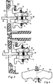
- FIG. 2 is a partial sectional view along the section line A - B in Fig.1, the arrangement the functional elements of the contact block 1 shown.
- the bearing piece by wobble riveting 16 2 attached at the Support frame 6 preferably the bearing piece by wobble riveting 16 2 attached.
- This has window 7 through which the contact blades 3 and 4 are guided.
- the side walls 8 of the windows 7 a lateral guidance of the Contact blades 3 and 4 and the central part 9 of the bearing piece 2 serves as a pivot bearing 10 for the contact lamellae 3 and 4.
- the contact blades 3 and 4 are on their contact side with recesses 13 and 14 provided which outside the axis of symmetry 15 of the Contact blades 3 and 4 are provided and the edges of the Grasp the middle part 9.
- the Support frame 6 packages of contact blades 3 and 4 and contact force springs 5 provided.
- the contact forces 5 are attached to pin 17 on the support frame. After that the individual packages of contact lamellae 3 and 4 in the for this provided window 7 of the support frame 6 each such introduced that the recesses 18 on the back of the contact blades 3 and 4 face the contact force springs 5.
- FIG. 3 shows the spatial arrangement of the isolating contact blocks 1 for the connecting busbar 19 and the outgoing busbar 20 for a circuit breaker, not shown in a low-voltage switchgear.
- FIG. 4 schematically shows a possible advantageous form a contact blade 3; 4 shown in side view.
- this is on your Contact side 26 provided with recesses 13 and 14, which outside the axis of symmetry 15 of the contact lamella 3; 4 provided are.
- the contact lamella engages 3; 4 with one of these recesses 13 or 14 the indicated Middle part 9 of the bearing piece 2 and is thus in the pivot bearing 10 thereby formed is pivotally locked.
- On the rear 27 of the contact lamella 3; 4 is a middle one Recess 18 is provided, into which the contact force springs 5 be introduced.
- isolating contact blocks in the existing one Switchgear can be done at any time. It is therefore only then isolating contact blocks 1 required in the switchgear use when the appropriate position with a circuit breaker to be filled. It also draws the isolating contact block according to the invention by a small Number of parts and an uncomplicated assembly.
Landscapes
- Engineering & Computer Science (AREA)
- Power Engineering (AREA)
- Contacts (AREA)
- Trip Switchboards (AREA)
Abstract
Description
Das Lagerstück ist mit dem rahmenartigen Tragrahmen vernietet oder verstemmt.
Es weist zur Aufnahme der Kontaktlamellen Fenster auf, deren Seitenwände eine seitliche Führung der Kontaktlamellen bilden und deren Kante am Mittelteil als Schwenklager für die Kontaktlamellen dient. Die Fensterkanten in den abgewinkelten Armen des Lagerstücks bilden Lagerkanten zur Begrenzung des Schwenkwinkels der Kontaktlamellen.
Die Kontaktkraftfedern sind vorzugsweise als Schraubenfedern ausgebildet.
Dabei ist es vorteilhaft, daß jede Kontaktkraftfeder je zwei nebeneinander angeordnete Kontaktlamellen beaufschlagt. Die Kontaktlamellen sind auf ihrer Kontaktseite mit Ausnehmungen versehen die außerhalb der Symmetrieachse der Kontaktlamellen vorgesehen sind und eine asymmetrische Lagerung im Lagerstück gewährleisten.
Auf ihrer Rückseite weisen die Kontaktlamellen mittig in ihrer Symmetrieachse angeordnete Ausnehmungen zur Aufnahme und Führung der als Schraubenfedern ausgebildeten Kontaktkraftfedern auf.
Claims (12)
- Trennkontaktblock (1) für Einschub-Leistungsschalter zur Verbindung beziehungsweise Trennung relativ zueinander bewegbarer Stromschienen (19, 20, 24, 25), bestehend aus einem Gehäuse und in dem Gehäuse parallel zueinander und relativ zueinander bewegbar angeordneten brückenartigen Kontaktstücken (3, 4), die an ihren Enden Kontaktflächen zur Anlage an den zu verbindenden oder zu trennenden Stromschienen besitzen und die durch Federn (5) gegen die Stromschienen (19, 20, 24, 25) vorgespannt sind, wobei jeweils zwei Kontaktstücke (3, 4) zur Bildung paralleler Strombahnen einander gegenüberstehend angeordnet sind,
gekennzeichnet durch
einen Tragrahmen (6), ein an diesem Tragrahmen (6) befestigtes, zweifach schräg abgewinkeltes Lagerstück (2), in diesem Lagerstück (2) schwenkbar gelagerte, seitlich geführte und in ihrem Schwenkwinkel begrenzte Kontaktlamellen (3; 4), deren Kontaktkraft durch am Tragrahmen (6) abgestützte, die Kontaktlamellen (3; 4) in die Richtung zu ihrer Kontaktseite beaufschlagende, Kontaktkraftfedern (5) bestimmt ist. - Trennkontaktblock nach Anspruch 1,
dadurch gekennzeichnet,
daß der Tragrahmen (6) zur Befestigung des Trennkontaktblockes (1) im Einschubrahmen der Schaltanlage Haltewinkel (22) aufweist. - Trennkontaktblock nach Anspruch 1,
dadurch gekennzeichnet,
daß der Tragrahmen (6) zur Sicherung der Kontaktkraftfedern (5) mit Zapfen (17) versehen ist. - Trennkontaktblock nach Anspruch 1,
dadurch gekennzeichnet,
daß das Lagerstück (2) zur Aufnahme der Kontaktlamellen (3; 4) Fenster (7) aufweist. - Trennkontaktblock nach Anspruch 1,
dadurch gekennzeichnet,
daß die Seitenwände (8) der Fenster (7) eine seitliche Führung der Kontaktlamellen (3; 4) bilden. - Trennkontaktblock nach Anspruch 1,
dadurch gekennzeichnet,
daß die Kante am Mittelteil (9) des Lagerstücks (2) als Schwenklager (10) für die Kontaktlamellen (3; 4) ausgebildet ist. - Trennkontaktblock nach Anspruch 1,
dadurch gekennzeichnet,
daß die Kanten der Fenster (7) an den Schenkelenden der abgewinkelten Arme (11) des Lagerstücks (2) Lagerkanten (12) zur Begrenzung des Schwenkwinkels der Kontaktlamellen (3; 4) bilden. - Trennkontaktblock nach Anspruch 1,
dadurch gekennzeichnet,
daß das Lagerstück (2) mit dem rahmenartigen Tragrahmen (6) vernietet oder verstemmt ist. - Trennkontaktblock nach Anspruch 1,
dadurch gekennzeichnet,
daß die Kontaktkraftfedern (5) als Schraubenfedern ausgebildet sind. - Trennkontaktblock nach Anspruch 1,
dadurch gekennzeichnet,
daß jede Kontaktkraftfeder (5) je zwei nebeneinander angeordnete Kontaktlamellen (3; 4) beaufschlagt. - Trennkontaktblock nach Anspruch 1,
dadurch gekennzeichnet,
daß die Kontaktlamellen (3; 4) auf ihrer Kontaktseite mit Ausnehmungen (13; 14) versehen sind, die außerhalb der Symmetrieachse (15) der Kontaktlamellen (3; 4) angeordnet sind. - Trennkontaktblock nach Anspruch 1,
dadurch gekennzeichnet,
daß die Kontaktlamellen (3; 4) auf ihrer Rückseite (27) mittig in ihrer Symmetrieachse (15) angeordnete Ausnehmungen (18) zur Aufnahme und Führung der als Schraubenfedern ausgebildeten Kontaktkraftfedern (5) aufweisen.
Applications Claiming Priority (2)
| Application Number | Priority Date | Filing Date | Title |
|---|---|---|---|
| DE19906176 | 1999-02-05 | ||
| DE1999106176 DE19906176A1 (de) | 1999-02-05 | 1999-02-05 | Trennkontaktblock für Einschub-Leistungsschalter |
Publications (3)
| Publication Number | Publication Date |
|---|---|
| EP1026801A2 true EP1026801A2 (de) | 2000-08-09 |
| EP1026801A3 EP1026801A3 (de) | 2000-11-29 |
| EP1026801B1 EP1026801B1 (de) | 2008-10-08 |
Family
ID=7897496
Family Applications (1)
| Application Number | Title | Priority Date | Filing Date |
|---|---|---|---|
| EP20000250035 Expired - Lifetime EP1026801B1 (de) | 1999-02-05 | 2000-02-03 | Trennkontaktblock für Einschub-Leistungsschalter |
Country Status (2)
| Country | Link |
|---|---|
| EP (1) | EP1026801B1 (de) |
| DE (2) | DE19906176A1 (de) |
Cited By (2)
| Publication number | Priority date | Publication date | Assignee | Title |
|---|---|---|---|---|
| CN106683953A (zh) * | 2017-03-14 | 2017-05-17 | 江苏高博锐电气有限公司 | 一种浮动式接线端子 |
| CN119681829A (zh) * | 2024-11-12 | 2025-03-25 | 浙江舜宇智领技术有限公司 | 镜头模组滚铆设备、镜头模组滚铆方法和镜头模组 |
Families Citing this family (1)
| Publication number | Priority date | Publication date | Assignee | Title |
|---|---|---|---|---|
| WO2025235268A1 (en) * | 2024-05-04 | 2025-11-13 | Ennovi Industries, Inc. | Electrical connector assembly with damping |
Citations (7)
| Publication number | Priority date | Publication date | Assignee | Title |
|---|---|---|---|---|
| US2751471A (en) | 1953-02-12 | 1956-06-19 | Fed Electric Prod Co | Contact assembly |
| US2872659A (en) | 1953-10-30 | 1959-02-03 | Electric Products Company | Contact assembly |
| US3201556A (en) | 1963-07-19 | 1965-08-17 | Gen Electric | Self-aligning disconnect assembly |
| US3427419A (en) | 1966-03-31 | 1969-02-11 | Westinghouse Electric Corp | Disconnecting contact assembly for electrical apparatus |
| US4486636A (en) | 1982-09-30 | 1984-12-04 | Siemens Aktiengesellschaft | Break contact arrangement for pullout-type switchgear |
| US4555604A (en) | 1983-12-06 | 1985-11-26 | Westinghouse Electric Corp. | Circuit breaker having improved stab assembly |
| DE4405900A1 (de) | 1994-02-18 | 1995-08-24 | Siemens Ag | Trennkontaktblock mit relativ zueinander bewegbar angeordneten brückenartigen Kontaktstücken |
-
1999
- 1999-02-05 DE DE1999106176 patent/DE19906176A1/de not_active Ceased
-
2000
- 2000-02-03 EP EP20000250035 patent/EP1026801B1/de not_active Expired - Lifetime
- 2000-02-03 DE DE50015384T patent/DE50015384D1/de not_active Expired - Lifetime
Patent Citations (8)
| Publication number | Priority date | Publication date | Assignee | Title |
|---|---|---|---|---|
| US2751471A (en) | 1953-02-12 | 1956-06-19 | Fed Electric Prod Co | Contact assembly |
| US2872659A (en) | 1953-10-30 | 1959-02-03 | Electric Products Company | Contact assembly |
| US3201556A (en) | 1963-07-19 | 1965-08-17 | Gen Electric | Self-aligning disconnect assembly |
| US3427419A (en) | 1966-03-31 | 1969-02-11 | Westinghouse Electric Corp | Disconnecting contact assembly for electrical apparatus |
| US4486636A (en) | 1982-09-30 | 1984-12-04 | Siemens Aktiengesellschaft | Break contact arrangement for pullout-type switchgear |
| EP0107611B1 (de) | 1982-09-30 | 1986-08-20 | Siemens Aktiengesellschaft | Trennkontaktanordnung mit brückenartigen Kontaktlamellen für ausfahrbare Schaltgeräte |
| US4555604A (en) | 1983-12-06 | 1985-11-26 | Westinghouse Electric Corp. | Circuit breaker having improved stab assembly |
| DE4405900A1 (de) | 1994-02-18 | 1995-08-24 | Siemens Ag | Trennkontaktblock mit relativ zueinander bewegbar angeordneten brückenartigen Kontaktstücken |
Cited By (2)
| Publication number | Priority date | Publication date | Assignee | Title |
|---|---|---|---|---|
| CN106683953A (zh) * | 2017-03-14 | 2017-05-17 | 江苏高博锐电气有限公司 | 一种浮动式接线端子 |
| CN119681829A (zh) * | 2024-11-12 | 2025-03-25 | 浙江舜宇智领技术有限公司 | 镜头模组滚铆设备、镜头模组滚铆方法和镜头模组 |
Also Published As
| Publication number | Publication date |
|---|---|
| DE50015384D1 (de) | 2008-11-20 |
| EP1026801B1 (de) | 2008-10-08 |
| DE19906176A1 (de) | 2000-08-10 |
| EP1026801A3 (de) | 2000-11-29 |
Similar Documents
| Publication | Publication Date | Title |
|---|---|---|
| EP1856709B1 (de) | Elektromechanisches schaltgerät | |
| DE1293278B (de) | Schaltgeraetetafel | |
| DE3101532C2 (de) | Stecksockel für Niederspannungs-Schutzschalter | |
| DE10003266A1 (de) | Stromkreisunterbrechereinrichtung | |
| AT506801B1 (de) | Nh-sicherungsschaltgerät | |
| EP3276761B1 (de) | Befestigungsvorrichtung für ein in einem gehäuse befindliches elektrisches bauteil | |
| DE69404001T2 (de) | Anschlusskasten | |
| EP0465883B1 (de) | Elektrische Anschlussklemme zum Befestigen auf einer Tragschiene | |
| EP1246332A2 (de) | Installationsgerät für ein Sammelschienensystem | |
| EP1026801A2 (de) | Trennkontaktblock für Einschub-Leistungsschalter | |
| DE102012203554A1 (de) | Sammelschienenabgreifklemme | |
| WO2000011768A1 (de) | Installationsgerät zur montage an einer hutschiene | |
| DE1178131B (de) | Trennschalter mit Sicherungspatronen | |
| DE2851738C2 (de) | Kontaktanordnung | |
| EP0917751B1 (de) | Vorrichtung zum verbinden eines elektrischen schaltgerätes mit einer sammelschiene und einer tragschiene | |
| DE69808836T2 (de) | Adapter zur modularen Verbindung elektrischer Geräte zu einem elektrischen Verteilungssystem auf Basis von Schiene | |
| DE2246964C3 (de) | Schutzschaltereinrichtung | |
| DE4422123A1 (de) | Adapter für Stromsammelschienen | |
| EP1253610B1 (de) | Adapter für das Kontaktieren von Lasttrennschaltern auf Stromsammelschienen | |
| EP1058281B1 (de) | Niederspannungs-Schaltgerät mit Anschlussschienen sowie Verfahren zur Erkennung des Bemessungsstromes des Schaltgerätes | |
| DE10113697B4 (de) | Auf Stromschienen einer elektrischen Einrichtung anzuordnendes Teil | |
| DE29609824U1 (de) | Niederspannungs-Leistungsschalter mit einem Kontaktträger | |
| DE1115804B (de) | Elektrische Reihenklemme zum Aufstecken auf eine C-foermige Tragschiene | |
| DE2358571C3 (de) | Anordnung zur Zwangsführung von Kontaktfedern | |
| DE2338982A1 (de) | Sicherungstrennschalter |
Legal Events
| Date | Code | Title | Description |
|---|---|---|---|
| PUAI | Public reference made under article 153(3) epc to a published international application that has entered the european phase |
Free format text: ORIGINAL CODE: 0009012 |
|
| AK | Designated contracting states |
Kind code of ref document: A2 Designated state(s): DE FR GB IT |
|
| AX | Request for extension of the european patent |
Free format text: AL;LT;LV;MK;RO;SI |
|
| PUAL | Search report despatched |
Free format text: ORIGINAL CODE: 0009013 |
|
| AK | Designated contracting states |
Kind code of ref document: A3 Designated state(s): AT BE CH CY DE DK ES FI FR GB GR IE IT LI LU MC NL PT SE |
|
| AX | Request for extension of the european patent |
Free format text: AL;LT;LV;MK;RO;SI |
|
| 17P | Request for examination filed |
Effective date: 20010305 |
|
| AKX | Designation fees paid |
Free format text: DE FR GB IT |
|
| 17Q | First examination report despatched |
Effective date: 20070727 |
|
| GRAP | Despatch of communication of intention to grant a patent |
Free format text: ORIGINAL CODE: EPIDOSNIGR1 |
|
| GRAS | Grant fee paid |
Free format text: ORIGINAL CODE: EPIDOSNIGR3 |
|
| GRAA | (expected) grant |
Free format text: ORIGINAL CODE: 0009210 |
|
| AK | Designated contracting states |
Kind code of ref document: B1 Designated state(s): DE FR GB IT |
|
| REG | Reference to a national code |
Ref country code: GB Ref legal event code: FG4D Free format text: NOT ENGLISH |
|
| REF | Corresponds to: |
Ref document number: 50015384 Country of ref document: DE Date of ref document: 20081120 Kind code of ref document: P |
|
| PLBE | No opposition filed within time limit |
Free format text: ORIGINAL CODE: 0009261 |
|
| STAA | Information on the status of an ep patent application or granted ep patent |
Free format text: STATUS: NO OPPOSITION FILED WITHIN TIME LIMIT |
|
| 26N | No opposition filed |
Effective date: 20090709 |
|
| GBPC | Gb: european patent ceased through non-payment of renewal fee |
Effective date: 20090203 |
|
| REG | Reference to a national code |
Ref country code: FR Ref legal event code: ST Effective date: 20091030 |
|
| PG25 | Lapsed in a contracting state [announced via postgrant information from national office to epo] |
Ref country code: FR Free format text: LAPSE BECAUSE OF NON-PAYMENT OF DUE FEES Effective date: 20090302 Ref country code: GB Free format text: LAPSE BECAUSE OF NON-PAYMENT OF DUE FEES Effective date: 20090203 |
|
| PG25 | Lapsed in a contracting state [announced via postgrant information from national office to epo] |
Ref country code: IT Free format text: LAPSE BECAUSE OF NON-PAYMENT OF DUE FEES Effective date: 20090203 |
|
| PGFP | Annual fee paid to national office [announced via postgrant information from national office to epo] |
Ref country code: DE Payment date: 20130419 Year of fee payment: 14 |
|
| REG | Reference to a national code |
Ref country code: DE Ref legal event code: R119 Ref document number: 50015384 Country of ref document: DE |
|
| REG | Reference to a national code |
Ref country code: DE Ref legal event code: R119 Ref document number: 50015384 Country of ref document: DE Effective date: 20140902 |
|
| PG25 | Lapsed in a contracting state [announced via postgrant information from national office to epo] |
Ref country code: DE Free format text: LAPSE BECAUSE OF NON-PAYMENT OF DUE FEES Effective date: 20140902 |