EP1026099B1 - Montagemaschine für pilzförmige Flaschenstopfen - Google Patents
Montagemaschine für pilzförmige Flaschenstopfen Download PDFInfo
- Publication number
- EP1026099B1 EP1026099B1 EP00101808A EP00101808A EP1026099B1 EP 1026099 B1 EP1026099 B1 EP 1026099B1 EP 00101808 A EP00101808 A EP 00101808A EP 00101808 A EP00101808 A EP 00101808A EP 1026099 B1 EP1026099 B1 EP 1026099B1
- Authority
- EP
- European Patent Office
- Prior art keywords
- path
- conveyor
- jaws
- shanks
- manner
- Prior art date
- Legal status (The legal status is an assumption and is not a legal conclusion. Google has not performed a legal analysis and makes no representation as to the accuracy of the status listed.)
- Expired - Lifetime
Links
- 239000000853 adhesive Substances 0.000 claims abstract description 20
- 230000001070 adhesive effect Effects 0.000 claims abstract description 20
- 239000007799 cork Substances 0.000 claims abstract description 7
- 239000000463 material Substances 0.000 claims abstract description 5
- 239000004033 plastic Substances 0.000 claims abstract description 4
- 229920003023 plastic Polymers 0.000 claims abstract description 4
- 239000002023 wood Substances 0.000 claims abstract description 4
- 238000003780 insertion Methods 0.000 claims description 7
- 230000037431 insertion Effects 0.000 claims description 7
- 230000000750 progressive effect Effects 0.000 claims description 3
- 239000012530 fluid Substances 0.000 claims 1
- 238000000151 deposition Methods 0.000 abstract 1
- 230000033001 locomotion Effects 0.000 description 3
- 230000010355 oscillation Effects 0.000 description 2
- 230000005540 biological transmission Effects 0.000 description 1
- 230000002093 peripheral effect Effects 0.000 description 1
- 230000007704 transition Effects 0.000 description 1
Images


Classifications
-
- B—PERFORMING OPERATIONS; TRANSPORTING
- B23—MACHINE TOOLS; METAL-WORKING NOT OTHERWISE PROVIDED FOR
- B23P—METAL-WORKING NOT OTHERWISE PROVIDED FOR; COMBINED OPERATIONS; UNIVERSAL MACHINE TOOLS
- B23P19/00—Machines for simply fitting together or separating metal parts or objects, or metal and non-metal parts, whether or not involving some deformation; Tools or devices therefor so far as not provided for in other classes
- B23P19/04—Machines for simply fitting together or separating metal parts or objects, or metal and non-metal parts, whether or not involving some deformation; Tools or devices therefor so far as not provided for in other classes for assembling or disassembling parts
-
- B—PERFORMING OPERATIONS; TRANSPORTING
- B27—WORKING OR PRESERVING WOOD OR SIMILAR MATERIAL; NAILING OR STAPLING MACHINES IN GENERAL
- B27J—MECHANICAL WORKING OF CANE, CORK, OR SIMILAR MATERIALS
- B27J5/00—Mechanical working of cork
Definitions
- the present invention relates to an assembly machine for mushroom-shaped stoppers for bottles, which stoppers comprise a shank of cork and a head of plastics, wood or equivalent material, wherein the head has a central seat into which an end portion of the shank is inserted with the interposition of an adhesive.
- Assembly machines are already known in which the transporting means are constituted by an intermittently rotating carousel.
- a peripheral region of the carousel comprises a succession of equidistant seats which receive the heads of the stoppers from a feeder.
- a station which comprises an adhesive-dispenser and a subsequent station which comprises a pushing device which inserts each shank, coming from a shank-feeder, under pressure into the seat of the associated head with the interposition of the adhesive.
- the intermittent rotational movement of the carousel is dictated by the fact that the heads have to stop first in the station for the application of the adhesive and then in the station for the insertion of the shanks.
- the main object of the present invention is to provide an assembly machine of the type in question which, owing to its continuous operation, lends itself to the automatic assembly of mushroom-shaped stoppers with high production rates.
- the high production rates are obtained owing to the fact that the means for transporting the heads comprise a continuously movable endless conveyor, and also the shanks are transported by a second endless conveyor movable continuously in synchronism with the first conveyor.
- the insertion means also carry out their work continuously.
- a mushroom-shaped stopper for bottles comprises a shank A of cork and a head B of plastics, wood or equivalent material.
- the head B has a blind central cylindrical seat C for receiving a corresponding end portion of the shank A.
- a cork shank A is engaged in the seat C with the interposition of the adhesive D.
- the shank A has been inserted fully into the seat C of the head B, and the adhesive, which, owing to the pressure of the shank A, has been distributed in a thin layer, also indicated D, gradually sets until it is completely hard.
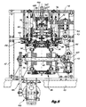
- the machine comprises a bench 10 which carries a frame having lateral uprights 12 which in their turn carry an upper plate 14 ( Figures 4, 5, 6, 8, 9 and 14).
- a substantially horizontal assembly path which starts on the left and finishes on the right in Figure 4 is defined inside the machine frame. At the start of the path is a feeder for the heads B of Figures 1 to 3 which is generally indicated 18.
- the feeder 18 will be described in detail hereinafter with reference to Figures 10 and 11.
- An adhesive-dispenser of known type which is generally indicated 20 and is shown in Figure 10, as well as in Figure 4, is arranged at the location of the head-feeder 18.
- the adhesive-feeder 20 comprises a nozzle 22 and is controlled in such a manner that the nozzle 22 lets fall a drop or measure of adhesive D, as in Figure 3, II, each time a head B stops beneath said nozzle.
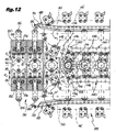
- the machine comprises a feeder for shanks A, which is generally indicated 24 and which is shown more clearly in Figures 10 and 12, with reference to which it will be described in detail.
- a first continuously movable endless conveyor which is used to transport the successive heads B from the beginning to the end of the path, is generally indicated 26 in Figure 4.
- the details of the first conveyor 26 will be described hereinafter with particular reference to Figures 4, 5, 8, 10, 11, 12 and 13.
- a second endless conveyor Associated with the shank-feeder 24 is a second endless conveyor generally indicated 28.
- This second conveyor 28 is movable continuously in synchronism with the first conveyor 26 and is capable of taking successive shanks A from their feeder 24 and transporting each of them to a position aligned above the seat C of a corresponding head B.
- the details of the second conveyor 28 will be described hereinafter with special reference to Figures 5, 6, 7, 9, 12 and 14.
- the assembly machine also comprises insertion means for carrying out stages III and IV of Figure 3.
- the insertion means comprise a pressure device which is generally indicated 30.
- the pressure device 30 extends above the portion of the path in which the shanks A are transported by the second conveyor 28 and has a first portion 32 which is arranged and inclined in such a manner as to engage the shanks A and insert them gradually into the seats C of the heads B, and a second portion 34 which is arranged in such a manner as to keep the shanks A in a state in which they are pressed into the seats C, as in Figure 3, IV, until, along the path, the layer of adhesive D has set.
- the first conveyor 26 comprises a pair of endless chains 36 ( Figures 4, 5, 8, 10, 11 and 13) which are arranged side by side and which have driving sprockets 38 ( Figures 4 and 5) and driven sprockets 40 ( Figures 4, 6, 10 and 11).
- the driving sprockets 38 and the driven sprockets 40 are splined onto respective common transverse driving 42 ( Figures 4 and 5) and driven 44 ( Figures 4 and 10) shafts.
- the second conveyor 28 comprises a pair of endless chains 46 circulating in unison and guided by respective counter-rotating driving sprockets 48 ( Figures 5, 6, 7 and 14) and driven sprockets 50 ( Figures 6, 7, 8, 9 and 14) having upright axes.
- the pressure device 30 preferably comprises a third endless conveyor which is movable continuously in synchronism with the first and second conveyors 26, 28.
- the third conveyor 30 comprises a pair of chains 56 (also shown partially in Figure 6) which are arranged side by side and which circulate in synchronism around driving sprockets 58 and driven sprockets 60 having horizontal transverse axes.
- the two driving sprockets 58 are connected to one another by a driving shaft 62 and the two driven sprockets 60 are connected to one another by a driven shaft 64.
- the three conveyors 26, 28 and 30 are controlled in unison by an electrical gear-motor carried by the table 10 and shown in Figures 4 and 5 where it is marked 64.
- the driving sprockets 38 of the first conveyor 26, 48 of the second conveyor and 58 of the third conveyor are arranged downstream of the path (on the right in Figure 4) and are connected in common to the gear-motor 64 by means of a train of gears.
- the output shaft of the gear-motor 64 is connected by a toothed belt drive 66 to the driving shaft 42 of the first conveyor 26.
- the motion is then transmitted from the driving shaft 42 to one of the driving shafts 52, the one on the right in Figure 5, of the second conveyor 28 by means of a bevel gear pair 68, a cardan shaft 70 and a pair of spur gears 72.
- the two chains 36 of the first conveyor 26, arranged side by side, are connected to one another by a succession of slide supports in the form of cross-members 76 which connect the two chains 36 to one another in the manner of bridges.
- Each slide support or bridge 76 carries a pair of first jaws 78.
- the jaws 78 are in the form of slides which are transversely slidable on the respective support 76 towards one another and in the opposite direction, in accordance with the double arrows F1 ( Figures 12 and 13).
- the first jaws 78 are recessed substantially in a V shape in order to surround respective heads B.
- the pairs of first jaws 78 can be opened out and moved towards one another in accordance with the double arrows F1 in a yielding manner in order to adapt to heads B having different diameters.
- the heads of the mushroom-shaped stoppers of the type in question have a diameter of the order of 30 mm, but this diameter can vary by a few millimetres more or less depending on the manufacturers and depending on the preferences of the bottlers.
- first jaws 78 can adapt to heads of different diameters makes the assembly machine illustrated and described here suitable for the assembly of stoppers having heads of different diameters without having to carry out adjustment work or setting-up work on the machine in the transition from one assembly campaign to another.
- Each slide support or cross-member 76 comprises a pair of opposing tubular components 80 in each of which is slidably mounted a push rod 82 which is movable in accordance with the double arrows F1.
- Each rod 82 is fast with a respective jaw 78.
- Each rod 82 is urged by a respective helical spring 84 in the opening direction of the jaws 78.
- Each push rod 82 carries, at its outer end, that is to say, remote from the jaw 78 carried by the other rod 82, a follower member 86 in the form of a roller.
- the first conveyor 26 is flanked by a pair of opposing rails 88 of wear-resistant material which extend along the path and which act as linear cams engageable by the follower members or rollers 86.
- the two rails 88 have initial converging portions 90 in order, at the start of the path, to move the two jaws 78 of each pair towards one another against the force of their springs 84 in order to lock a head B between the jaws and keep it locked until the end of the path is reached.
- each rail 88 is supported by an oscillating member constituted by a pair of arms 92 (92a, 92b) arranged near the beginning and near the end of the path, as shown in particular in Figure 4.
- the arms 92a, 92b of each pair are pivoted by means of respective pins 94 to fixed framework members 96.
- each pair the two arms 92a, 92b are connected to one another by a connecting rod 96 whose length can be adjusted because it is constructed in the form of a turnbuckle.
- the connecting rod 96 is connected to the arm 92a on the right (in Figure 8) by means of an articulation 98a arranged above the associated pivot 94 and is connected to the arm 92b on the left (in Figure 8) by means of an articulation 98b arranged below the associated pivot 94.
- the two arms 92a, 92b are biased towards one another by a transverse spring tie rod 100, the function of which is to absorb the differences in diameter of the various types of head B.
- the ability to adjust the length of the connecting rods 96 enables the distance between the rails 88 and the path of the heads B to be adjusted symmetrically once and for all.
- the feeder 18 comprises an arrival chute 102 along which the heads B slide in alignment in accordance with the arrow F2 in Figure 11.
- the arrival chute 102 opens out laterally into the path of the first jaws 78 in a position that is raised relative to those jaws.
- the feeder 18 also comprises a leaving chute 104.
- the latter extends with a downward slope in the downstream direction along an initial portion of the path of the heads B and has a median longitudinal slit 106.
- Each slide support or cross-member 76 has an entraining tooth 108.
- the entraining tooth 108 is capable of projecting upwards through the slit 106 in order to push a head B coming from the arrival chute 102 and deposit it between the first jaws 78 at the end of the leaving chute 104.
- the nozzle 22 of the adhesive-dispenser 20 is located just above the connecting region 110 and is thus arranged or programmed to deposit, each time, a drop or measure of adhesive, such as that indicated D in Figure 3, II, in the seat C of a head B which has temporarily stopped in the connecting region 110, and immediately before the entraining tooth 108 starts to entrain that head B.
- the chains 46 of the second conveyor 28 are carried by respective cantilevered support arms 112 constituted by a strong horizontal plate 114 and by an upright rib or gusset plate 116, shown more clearly in Figure 14.
- each cantilevered arm 112 is rotatably mounted in the manner of a flag about the respective driving shaft 52 which is arranged towards the downstream end of the path.
- the transmission shaft or pin 54 of the driven sprocket 50 of each chain 46 of the second conveyor 28 is supported by the free end of the arm 112, which end is remote from the driving shaft 52.
- Each of the chains 46 of the second conveyor 28 is provided with second equidistant jaws 118 which form respective pairs of opposing jaws. Those pairs of second jaws 118 are recessed substantially in a V-shape in order to be able to grip the successive shanks A laterally, taking them from the feeder 24, at a point on the path located downstream of the adhesive-dispenser 20.
- the two chains 46 of the second conveyor 28 are flanked by a pair of rails 120 carried by the plates 114 of the respective cantilevered arms 112.
- the rails 120 act as linear cams and are engaged by the pins of the chains 46 in order to keep the second jaws 118 in a position clamped around the shanks until, as will be seen hereinafter, the shanks A have been engaged in the seats C of the heads B.
- the rails 120 have converging lead-in portions 121 which promote a progressive approach of the second jaws 118 when the latter start to grip a shank A.
- the two arms 112 of the second conveyor 28, which are rotatable in the manner of a flag, are connected to one another ( Figure 9) by a pair of levers 122 pivoted at 124 on a cross-member 126 which extends between two uprights 12.
- the two levers 122 are connected to the respective cantilevered arms 112 by means of adjustable articulations 127 (see also Figures 4 and 14).
- the two levers 122 have toothed sectors 128 which are meshed with one another in order to ensure that the second jaws 118 are symmetrical relative to a median line of translation of the shanks A.
- the spring 130 is used for the resilient biasing towards one another of the cantilevered arms 112 in order to exert the above clamping force on the shanks A.
- the feeder 24 comprises an upright tubular arrival duct 132 in which the shanks A descend in a stack.
- a longitudinal bearing ledge 134 for each successive lowermost shank A of the stack.
- the second jaws 118 are arranged in such a manner as to grip the lowermost shank, causing it to slide forwards on the ledge 134.
- the active paths of the two chains 46 comprise converging initial portions 136 ( Figure 12), in part defined by the converging initial portions 122 of the rails 120.
- the converging portions 136 are disposed at the location of the ledge 134 in order to grip each shank A with a progressive clamping force.
- the driving shaft 62 and the driven shaft 64 of the third conveyor 30 are carried by a movable member in the form of a frame 138.
- the frame 138 is suspended from the upper plate 14 ( Figure 4) of the machine housing by a pantographic linkage 140 which ensures the substantially vertical lifting and lowering of the movable member or frame 138, keeping it parallel with itself.
- the frame 138 is urged resiliently downwards by resilient means in the form of helical springs 142.
- each of the wheels 144 accompanies a shank A transported by the second jaws 118 and engages it, pressing it downwards along the first descending inclined portion 32 of the chains 56.
- the wheels 144 press on the shanks A, inserting them gradually into the seats C of the heads B.
- the wheels 144 hold the shanks A in a position pressed into the seats C, until the adhesive has set.
- a pressure device 30 which comprises, as pressure or thrust members, idle wheels or rollers 144, is advantageous because those members, being freely rotatable, do not exert on the shanks A oblique thrusts which could bring them out of alignment with the seats C of the heads B.
- the second conveyor 28 and the third conveyor 30 are arranged in such a manner that they can adapt to shanks A having different diameters and different lengths or heights, without it being necessary to modify the adjustments or setup of the machine when there is a changeover to the assembly of stoppers having shanks with different dimensions from those of a previous assembly campaign.
- cork shanks have diameters of the order of 20 mm, but those diameters can vary by approximately 2 millimetres more or less.
- the flag-like oscillation ability of the cantilevered arms 112 of the second conveyor 28, in conjunction with the spring 130 of Figure 9, enables the second jaws 118 to adapt to all those different diameters.
- cork shanks may have lengths or heights which are variable, for example, from 20 to 30 mm.
- the third conveyor 30 adapts automatically to shanks A of different lengths owing to the vertical oscillation ability of the movable member 138 of the third conveyor 30, in conjunction with the yielding thrust of its springs 142.
Landscapes
- Engineering & Computer Science (AREA)
- Mechanical Engineering (AREA)
- Life Sciences & Earth Sciences (AREA)
- Forests & Forestry (AREA)
- Specific Conveyance Elements (AREA)
- Mushroom Cultivation (AREA)
- Making Paper Articles (AREA)
- Preparation Of Fruits And Vegetables (AREA)
- Sealing Of Jars (AREA)
Claims (17)
- Montagemaschine für pilzförmige Flaschenstopfen, die aus einem Fuß (A) aus Kork und einem Kopf (B) aus Kunststoff, Holz oder dergleichen bestehen, wobei der Kopf einen mittigen Sitz (C) hat, in den ein Ende des Fußes unter Zwischenschaltung einer Klebstoffschicht (D) eingesetzt wird, wobei die Maschine umfaßt:dadurch gekennzeichnet, daßeine Zuführeinrichtung (18) für die Köpfe,Transportmittel (26), die eine Bahn definieren und die am Beginn der Bahn die Köpfe (B) einzeln nacheinander von ihrer Zuführeinrichtung (18) empfangen und am Ende der Bahn die zusammengefügten Stopfen abgeben,eine Zuführeinrichtung (24) für die Füße, die so ausgebildet ist, daß sie jeweils einen Fuß (A) in einer zu dem Sitz (C) jedes der nacheinander transportierten Köpfe (B) ausgerichteten Stellung vorlegt,ein Klebstoff-Abgabeorgan (20), das entlang der Bahn angeordnet und so ausgebildet ist, daß es eine Dosis (D) flüssigen Klebstoffs zwischen jeden der nacheinander transportierten Köpfe (B) und den zugehörigen Fuß (A) eingibt,Einführmittel (30), die so ausgebildet sind, daß sie jeden Fuß (A) in den Sitz (C) des zugehörigen Kopfes (B) unter Zwischenschaltung des Klebstoffs (D) unter Druck einfügen,die Zuführeinrichtung (18) für die Köpfe (B) so ausgebildet ist, daß sie diese mit ihren nach oben offenen Sitzen (C) zuführen,die Transportmittel einen ersten kontinuierlich umlaufenden Endlosförderer (26) aufweisen, der mit gleichmäßig voneinander beabstandeten Paaren erster, einander gegenüberliegender Greifbacken (78) ausgerüstet ist, die die aufeinander folgenden Köpfe (B) am Beginn der Bahn erfassen und am Ende der Bahn freigeben,das Klebstoff-Abgabeorgan (20) so ausgebildet ist, daß es jeweils eine Klebstoffdosis (D) von oben auf den Boden jedes Sitzes (C) abgibt,der Zuführeinrichtung (24) für die Füße (A) ein zweiter Endlosförderer (28) zugeordnet ist, der mit dem ersten Endlosförderer (26) synchron kontinuierlich umläuft und mit gleichmäßig voneinander beabstandeten Paaren zweiter, einander gegenüberliegender Greifbacken (118) ausgerüstet ist, die so ausgebildet sind, daß sie die aufeinander folgenden Füße (A) seitlich erfassen, indem sie sie von der Zuführeinrichtung (24) an einer Stelle der Bahn abnehmen, die sich in Förderrichtung hinter dem Klebstoff-Abgabeorgan (20) befindet und jeden von diesen entlang eines folgenden Bahnabschnittes in eine Position bringen, die über dem für den entsprechen Kopf (B) vorgesehenen Sitz (C) zu diesem ausgerichtet ist,die Einführmittel eine Druckeinrichtung (30) aufweisen, die sich über dem genannten folgenden Bahnabschnitt erstreckt und einen ersten Abschnitt (32) aufweist, der so angeordnet und geneigt ist, daß er in Eingriff mit den Füßen (A) kommt und diese nacheinander in die Sitze (C) der Köpfe (B) einführt, sowie einen zweiten Abschnitt (34), der so angeordnet ist, daß er die Füße (A) unter Druck in den Sitzen (C) hält, bis die Klebstoffdosis (D) abgebunden hat.
- Montagemaschine nach Anspruch 1, dadurch gekennzeichnet, daß die Paare der ersten Greifbacken (78) voneinander weg und aufeinander zu nachgiebig beweglich sind, um sich an Köpfe (B) verschiedener Durchmesser anzupassen.
- Montagemaschine nach Anspruch 1 oder 2, dadurch gekennzeichnet, daß der erste Endlosförderer (26) eine Folge von Gleitträgern (76) aufweist, von denen jeder ein Paar der ersten Greifbacken (78) trägt, daß die ersten Greifbacken (78) jedes Paares als Schlitten ausgebildet sind, die auf dem jeweiligen Träger (76) zueinander und in entgegengesetzter Richtung quer verschiebbar sind und durch Federn (78) im Sinne eines gegenseitigen Spreizens beaufschlagt werden, daß jede der ersten Greifbacken (78) auf der von der anderen Greifbacke des Paares abgewandten Seite einen Tastkörper (86) hat, und daß der erste Endlosförderer (26) von einem Paar einander gegenüberliegender Schienen (88) flankiert ist, die sich entlang der Bahn erstrecken und als Linearnocken wirken, mit denen die Tastkörper (86) in Eingriff kommen und die konvergierende Eingangsabschnitte (90) haben, um die beiden ersten Greifbacken (78) jedes Paares gegeneinander zu verschieben, wodurch jeweils ein Kopf (B) erfasst und bis zum Bahnende eingespannt gehalten wird.
- Montagemaschine nach Anspruch 3, dadurch gekennzeichnet, daß jede Schiene (88) von einem Schwingkörper (92) getragen wird, wodurch sie sich in Richtung auf den ersten Förderer (26) und von diesem weg bewegen kann, und daß die beiden Schwingkörper (92) über wenigstens eine Koppelstange (96) miteinander verbunden sind, die an den Schwingkörpern so angelenkt ist, daß sich die Schienen (88) symmetrisch zu der Bahn einander annähern und voneinander entfernen, um ein zentriertes Einklemmen der Köpfe (B) zu gewährleisten, die von den ersten Greifbacken (78) erfaßt werden.
- Montagemaschine nach Anspruch 4, dadurch gekennzeichnet, daß die Koppelstange oder jede Koppelstange (96) eine einstellbare Länge hat, um den Abstand der Schienen (88) von der Bahn symmetrisch einstellen zu können.
- Montagemaschine nach einem der Ansprüche 3 bis 5, dadurch gekennzeichnet, daß der erste Förderer ein Paar endloser Ketten (36) hat, die einander gegenüberliegend angeordnet sind und Antriebsräder (38) sowie angetriebene Räder (40) haben, welche auf entsprechende, gemeinsame und in Querrichtung verlaufende Wellen (42, 44) aufgezogen sind, und daß die Gleitträger für die Greifbackenpaare aus Traversen (76) bestehen, die die beiden Ketten (36) in der Art von Stegen miteinander verbinden.
- Montagemaschine nach einem der Ansprüche 3 bis 6, dadurch gekennzeichnet, daß die Zuführeinrichtung (18) für die Köpfe eine Eingangsrutsche (102) hat, auf der die Köpfe (B) zueinander ausgerichtet gleiten und die seitlich in die Bahn der ersten Greifbacken (78) in einer Position mündet, die über den Greifbacken liegt, sowie eine Startrutsche (104), die sich in einer in Förderrichtung abfallenden Richtung über dem Eingangsabschnitt der Bahn erstreckt und einen mittleren Längsschlitz (106) aufweist, und daß jeder Gleitträger (76) für die ersten Greifbacken (78) einen Mitnehmerzahn (108) hat, der durch den Längsschlitz (106) nach oben vorsteht, um eine von der Eingangsrutsche (102) kommenden Kopf (B) vorzuschieben und ihn zwischen die ersten Greifbacken (78) am Ende der Startrutsche (104) abzulegen.
- Montagemaschine nach Anspruch 7, dadurch gekennzeichnet, daß das Klebstoff-Abgabeorgan (20) eine Düse (22) hat, die sich über dem Verbindungsbereich (110) zwischen der Eingangsrutsche (102) und der Startrutsche (104) befindet und so angeordnet ist, daß sie jedesmal einen Tropfen Klebstoff (D) in den Sitz (C) eines Kopfes (B) abgibt, der sich in Haltestellung in dem Verbindungsbereich (110) unmittelbar vor Beginn der Mitnahme des Kopfes (B) durch den Mitnehmerzahn (108) befindet.
- Montagemaschine nach einem der vorhergehenden Ansprüche, dadurch gekennzeichnet, daß der zweite Endlosförderer (28) ein Paar endloser Ketten (46) hat, die synchron zueinander umlaufen und über entsprechende Antriebsräder (48) und angetriebene Räder (50) mit vertikalen Achsen umgelenkt werden, wobei die Räder der einen Kette in entgegengesetzter Richtung zu denen der anderen Kette rotieren und jede Kette die zweiten, untereinander gleich ausgebildeten Greifbacken (118) der Paare trägt, daß die Ketten (46) im wesentlichen parallel gegenüberliegende Arbeitstrume haben, entlang denen die zweiten Greifbacken (118) die Füße (A) der Stopfen ergreifen und dabei einzeln nacheinander von der Zuführeinrichtung (24) abnehmen und sie entlang der Bahn in eine zu den Sitzen (C) der von den ersten Greifbacken (78) transportierten Köpfen (B) ausgerichtete Position bringen, wobei die zweiten Greifbacken (118) auf die Füße (A) eine so schwache Klemmkraft ausüben, daß die Füße unter Einwirkung der Druckeinrichtung (30) nach unten verschoben werden können.
- Montagemaschine nach Anspruch 9, dadurch gekennzeichnet, daß die Zuführeinrichtung (24) für die Füße einen vertikalen, rohrförmigen Eingangskanal (132) hat, in dem die übereinander gestapelten Füße (A) nach unten gelangen und an dessen Ende sich eine in Längsrichtung erstreckende Stützleiste (134) für den jeweils untersten Fuß (A) des Stapels befindet, daß die zweiten Greifbacken (118) so angeordnet sind, daß sie den jeweils untersten Fuß erfassen und ihn auf der Stützleiste (134) nach vorn schieben, und daß die Arbeitstrume der Ketten (46) des zweiten Förderers (28) konvergierende Eingangsabschnitte (136) haben, die sich im Bereich der Stützleiste (134) befinden, um jeden Fuß (A) mit progressiver Klemmung zu erfassen.
- Montagemaschine nach Anspruch 9 oder 10, dadurch gekennzeichnet, daß die Arbeitstrume der Ketten (46) des zweiten Förderers (28) von einem Paar einander gegenüberliegender Schienen (120) flankiert sind, die als Linearnocken wirken und an denen die Ketten anliegen, wodurch die zweiten Greifbacken (118) in der die Füße (A) klemmenden Position gehalten werden, bis die Füße in die Sitze (C) der Köpfe (B) eingesetzt sind.
- Montagemaschine nach Anspruch 10, dadurch gekennzeichnet, daß die Ketten (46) des zweiten Förderers (28) an Tragarmen (112) gehalten sind, die fliegend gelagert sind und von denen jeder nach Art einer Fahne schwenkbar um die Vertikalachse des zugehörigen Antriebsrades (48) gelagert ist, und daß die Tragarme (112) durch elastische Mittel aufeinander zu beaufschlagt sind, um auf die Füße (A) die erwähnte Klemmkraft auszuüben.
- Montagemaschine nach Anspruch 12, dadurch gekennzeichnet, daß die beiden schwenkbaren Tragarme (112) über zwei Hebel (122) miteinander verbunden sind, die ineinander eingreifende Zahnsektoren (128) haben und so ausgebildet sind, daß die Symmetrielage der zweiten Greifbacken (118) relativ zu einer mittleren Translationslinie der Füße (A) gewährleistet wird, und daß die elastischen Mittel aus einer Feder (130) bestehen, die zwischen die beiden Hebel (122) eingesetzt ist.
- Montagemaschine nach einem der vorhergehenden Ansprüche, dadurch gekennzeichnet, daß die Druckeinrichtung einen dritten Endlosförderer (30) aufweist, der synchron mit dem ersten und dem zweiten Förderer (26, 28) kontinuierlich umläuft und ein Paar nebeneinander angeordneter Ketten (56) hat, die synchron miteinander um Antriebsräder (58) und angetriebene Räder (60) mit horizontalen, in Querrichtung verlaufenden Achsen umlaufen und die eine Reihe von gleichmäßig voneinander beabstandeten, frei drehbaren Rädern oder Rollen (144) mit horizontalen Querachsen tragen, von denen jede einen von den zweiten Greifbacken (118) transportierten Fuß (A) begleitet und diesen dabei nach unten drückt, und daß die Umlaufbahn der beiden Ketten (56) ein unteres Arbeitstrum mit einem ersten Abschnitt (32) hat, der in Arbeitsrichtung abfällt und so angeordnet und geneigt ist, daß die Räder oder Rollen (144) in Eingriff mit den Füßen (A) kommen und diese unter Druck allmählich in die Sitze (C) der Köpfe (B) einfügen, sowie mit einem nachfolgenden, im wesentlichen horizontalen Abschnitt (34), der so angeordnet ist, daß er die Füße (A) unter Druck in den Sitzen (C) hält, bis der Klebstoff (D) abgebunden hat.
- Montagemaschine nach Anspruch 14, dadurch gekennzeichnet, daß der dritte Förderer (30) von einem im wesentlichen vertikal beweglichen Organ (138) getragen wird, das durch elastische Mittel (142) nach unten gedrückt wird.
- Montagemaschine nach Anspruch 15, dadurch gekennzeichnet, daß das bewegliche Organ (138) an einem Pantografengestänge (140) aufgehängt ist, das für eine parallele Lageverschiebung des Organs nach oben und nach unten sorgt.
- Montagemaschine nach einem der vorhergehenden Ansprüche, dadurch gekennzeichnet, daß der erste Förderer (26) wenigstens eine endlos umlaufende Kette (36) hat, die über ein Antriebsrad (38) und ein angetriebenes Rad (40) umgelenkt wird, daß der zweite Förderer (28) wenigstens eine endlos umlaufende Kette (46) hat, die über ein Antriebsrad (48) und ein angetriebenes Rad (50) umgelenkt wird, daß die Druckeinrichtung einen dritten Endlosförderer (30) mit wenigstens einer endlos umlaufenden Kette (56) hat, die über ein Antriebsrad (58) und ein angetriebenes Rad (60) umgelenkt wird und eine Reihe von Rädern oder Rollen (144) für die Druckausübung auf die Füße (A) trägt, und daß die Antriebsräder (38, 48, 58) der drei Förderer (26, 28, 30) am Ende der Bahn angeordnet und mit einem gemeinsamen Motor (64) über ein Zahnradgetriebe (68, 72, 74) verbunden sind, so daß die drei Förderer synchron miteinander umlaufen.
Applications Claiming Priority (2)
| Application Number | Priority Date | Filing Date | Title |
|---|---|---|---|
| ITTO990068 | 1999-02-02 | ||
| IT1999TO000068A IT1307127B1 (it) | 1999-02-02 | 1999-02-02 | Macchina assemblatrice per tappi a fungo per bottiglie |
Publications (3)
| Publication Number | Publication Date |
|---|---|
| EP1026099A2 EP1026099A2 (de) | 2000-08-09 |
| EP1026099A3 EP1026099A3 (de) | 2002-08-21 |
| EP1026099B1 true EP1026099B1 (de) | 2004-10-20 |
Family
ID=11417403
Family Applications (1)
| Application Number | Title | Priority Date | Filing Date |
|---|---|---|---|
| EP00101808A Expired - Lifetime EP1026099B1 (de) | 1999-02-02 | 2000-01-28 | Montagemaschine für pilzförmige Flaschenstopfen |
Country Status (4)
| Country | Link |
|---|---|
| EP (1) | EP1026099B1 (de) |
| AT (1) | ATE280093T1 (de) |
| DE (1) | DE60014983D1 (de) |
| IT (1) | IT1307127B1 (de) |
Families Citing this family (4)
| Publication number | Priority date | Publication date | Assignee | Title |
|---|---|---|---|---|
| US20100258522A1 (en) * | 2009-04-10 | 2010-10-14 | Tapones Escobar, S.A. | Glued synthetic cork and method of manufacture |
| CN112247532B (zh) * | 2020-10-23 | 2022-04-12 | 上海习锟机电科技有限公司 | 一种高效安全的滚动货架自动安装机 |
| CN114770086A (zh) * | 2022-05-19 | 2022-07-22 | 刘伟 | 一种水龙头连接件的密封圈安装装置 |
| CN118617073B (zh) * | 2024-06-13 | 2025-09-09 | 迈得医疗工业设备股份有限公司 | 生产设备 |
Family Cites Families (3)
| Publication number | Priority date | Publication date | Assignee | Title |
|---|---|---|---|---|
| FR1030684A (fr) * | 1950-11-30 | 1953-06-16 | Procédé de fabrication de bouchons à tête et machine en permettant la mise en oeuvre | |
| FR1332654A (fr) * | 1962-06-05 | 1963-07-19 | Valentin F Sarl | Machine pour insérer automatiquement une garniture en liège dans la cuvette prévue dans la tête de bouchons en matière plastique |
| US5161302A (en) * | 1991-08-07 | 1992-11-10 | Martin Mueller | Apparatus for forming sleeve and plunger assemblies |
-
1999
- 1999-02-02 IT IT1999TO000068A patent/IT1307127B1/it active
-
2000
- 2000-01-28 DE DE60014983T patent/DE60014983D1/de not_active Expired - Lifetime
- 2000-01-28 EP EP00101808A patent/EP1026099B1/de not_active Expired - Lifetime
- 2000-01-28 AT AT00101808T patent/ATE280093T1/de not_active IP Right Cessation
Also Published As
| Publication number | Publication date |
|---|---|
| EP1026099A3 (de) | 2002-08-21 |
| IT1307127B1 (it) | 2001-10-29 |
| ATE280093T1 (de) | 2004-11-15 |
| EP1026099A2 (de) | 2000-08-09 |
| DE60014983D1 (de) | 2004-11-25 |
| ITTO990068A1 (it) | 2000-08-02 |
Similar Documents
| Publication | Publication Date | Title |
|---|---|---|
| CN108723792B (zh) | 电容器多针焊接插壳注胶组装机 | |
| CN111747081B (zh) | 自动包装机 | |
| CN110302980B (zh) | 一种铝电解电容静态测试机 | |
| CN109192571B (zh) | 一种微动开关全自动组装生产系统及弹片分选上料装置 | |
| EP1035023B1 (de) | Foerdervorrichtung für Gegenstände | |
| CN116394323A (zh) | 一种菌菇切根机构、自动菌菇采收切根机及全自动菌菇处理线 | |
| CN116372078A (zh) | 一种金属零件的对冲锻造机构 | |
| EP1026099B1 (de) | Montagemaschine für pilzförmige Flaschenstopfen | |
| CN110171606B (zh) | 一种连续自动计数包装生产线 | |
| CN108773047B (zh) | 吹瓶机中的联动上坯机构 | |
| CN109346348B (zh) | 一种微动开关全自动组装生产系统及按挚分选上料装置 | |
| CN215774615U (zh) | 一种食用菌培养菌袋加工用全自动窝口插棒机 | |
| CN111136894B (zh) | 一种把手预热吹瓶生产线及其方法 | |
| JP2003095384A (ja) | ライン式キャッパーおよびそのキャッピング方法 | |
| CN110977266B (zh) | 一种桶盖自动组装焊接设备 | |
| CN209830798U (zh) | 一种拉紧器轴销自动装配装置 | |
| CN217050237U (zh) | 一种能整排进料的猴魁捏尖机 | |
| CN212570881U (zh) | 一种全自动涂胶压帽生产线 | |
| CN211969821U (zh) | 一种自动馒头码盘机 | |
| CN110948158A (zh) | 一种电连接件焊接设备及其方法 | |
| CN212075537U (zh) | 管材包装机 | |
| CN109367850B (zh) | 一种杯装饮品压盖机 | |
| CN115338298B (zh) | 一种汽车零部件骨架生产用折弯装置 | |
| CN217675314U (zh) | 一种气雾罐自动理瓶装置 | |
| CN114313815B (zh) | 一种能整排进料的猴魁捏尖机 |
Legal Events
| Date | Code | Title | Description |
|---|---|---|---|
| PUAI | Public reference made under article 153(3) epc to a published international application that has entered the european phase |
Free format text: ORIGINAL CODE: 0009012 |
|
| AK | Designated contracting states |
Kind code of ref document: A2 Designated state(s): AT BE CH CY DE DK ES FI FR GB GR IE IT LI LU MC NL PT SE |
|
| AX | Request for extension of the european patent |
Free format text: AL;LT;LV;MK;RO;SI |
|
| RIN1 | Information on inventor provided before grant (corrected) |
Inventor name: COPPO, VINCENZO Inventor name: SERRA, GIANCARLO Inventor name: OCCELLI, ROMANO |
|
| PUAL | Search report despatched |
Free format text: ORIGINAL CODE: 0009013 |
|
| AK | Designated contracting states |
Kind code of ref document: A3 Designated state(s): AT BE CH CY DE DK ES FI FR GB GR IE IT LI LU MC NL PT SE |
|
| AX | Request for extension of the european patent |
Free format text: AL;LT;LV;MK;RO;SI |
|
| RIC1 | Information provided on ipc code assigned before grant |
Free format text: 7B 65D 39/16 A, 7B 23P 19/04 B, 7B 27J 5/00 B |
|
| 17P | Request for examination filed |
Effective date: 20030130 |
|
| AKX | Designation fees paid |
Designated state(s): AT BE CH CY DE DK ES FI FR GB GR IE IT LI LU MC NL PT SE |
|
| GRAP | Despatch of communication of intention to grant a patent |
Free format text: ORIGINAL CODE: EPIDOSNIGR1 |
|
| GRAS | Grant fee paid |
Free format text: ORIGINAL CODE: EPIDOSNIGR3 |
|
| GRAA | (expected) grant |
Free format text: ORIGINAL CODE: 0009210 |
|
| AK | Designated contracting states |
Kind code of ref document: B1 Designated state(s): AT BE CH CY DE DK ES FI FR GB GR IE IT LI LU MC NL PT SE |
|
| PG25 | Lapsed in a contracting state [announced via postgrant information from national office to epo] |
Ref country code: IT Free format text: LAPSE BECAUSE OF FAILURE TO SUBMIT A TRANSLATION OF THE DESCRIPTION OR TO PAY THE FEE WITHIN THE PRESCRIBED TIME-LIMIT;WARNING: LAPSES OF ITALIAN PATENTS WITH EFFECTIVE DATE BEFORE 2007 MAY HAVE OCCURRED AT ANY TIME BEFORE 2007. THE CORRECT EFFECTIVE DATE MAY BE DIFFERENT FROM THE ONE RECORDED. Effective date: 20041020 Ref country code: AT Free format text: LAPSE BECAUSE OF FAILURE TO SUBMIT A TRANSLATION OF THE DESCRIPTION OR TO PAY THE FEE WITHIN THE PRESCRIBED TIME-LIMIT Effective date: 20041020 Ref country code: FR Free format text: LAPSE BECAUSE OF FAILURE TO SUBMIT A TRANSLATION OF THE DESCRIPTION OR TO PAY THE FEE WITHIN THE PRESCRIBED TIME-LIMIT Effective date: 20041020 Ref country code: NL Free format text: LAPSE BECAUSE OF FAILURE TO SUBMIT A TRANSLATION OF THE DESCRIPTION OR TO PAY THE FEE WITHIN THE PRESCRIBED TIME-LIMIT Effective date: 20041020 Ref country code: FI Free format text: LAPSE BECAUSE OF FAILURE TO SUBMIT A TRANSLATION OF THE DESCRIPTION OR TO PAY THE FEE WITHIN THE PRESCRIBED TIME-LIMIT Effective date: 20041020 Ref country code: CH Free format text: LAPSE BECAUSE OF FAILURE TO SUBMIT A TRANSLATION OF THE DESCRIPTION OR TO PAY THE FEE WITHIN THE PRESCRIBED TIME-LIMIT Effective date: 20041020 Ref country code: BE Free format text: LAPSE BECAUSE OF FAILURE TO SUBMIT A TRANSLATION OF THE DESCRIPTION OR TO PAY THE FEE WITHIN THE PRESCRIBED TIME-LIMIT Effective date: 20041020 Ref country code: LI Free format text: LAPSE BECAUSE OF FAILURE TO SUBMIT A TRANSLATION OF THE DESCRIPTION OR TO PAY THE FEE WITHIN THE PRESCRIBED TIME-LIMIT Effective date: 20041020 |
|
| REG | Reference to a national code |
Ref country code: GB Ref legal event code: FG4D |
|
| REG | Reference to a national code |
Ref country code: CH Ref legal event code: EP |
|
| REG | Reference to a national code |
Ref country code: IE Ref legal event code: FG4D |
|
| REF | Corresponds to: |
Ref document number: 60014983 Country of ref document: DE Date of ref document: 20041125 Kind code of ref document: P |
|
| PG25 | Lapsed in a contracting state [announced via postgrant information from national office to epo] |
Ref country code: DK Free format text: LAPSE BECAUSE OF FAILURE TO SUBMIT A TRANSLATION OF THE DESCRIPTION OR TO PAY THE FEE WITHIN THE PRESCRIBED TIME-LIMIT Effective date: 20050120 Ref country code: SE Free format text: LAPSE BECAUSE OF FAILURE TO SUBMIT A TRANSLATION OF THE DESCRIPTION OR TO PAY THE FEE WITHIN THE PRESCRIBED TIME-LIMIT Effective date: 20050120 Ref country code: GR Free format text: LAPSE BECAUSE OF FAILURE TO SUBMIT A TRANSLATION OF THE DESCRIPTION OR TO PAY THE FEE WITHIN THE PRESCRIBED TIME-LIMIT Effective date: 20050120 |
|
| PG25 | Lapsed in a contracting state [announced via postgrant information from national office to epo] |
Ref country code: DE Free format text: LAPSE BECAUSE OF FAILURE TO SUBMIT A TRANSLATION OF THE DESCRIPTION OR TO PAY THE FEE WITHIN THE PRESCRIBED TIME-LIMIT Effective date: 20050121 |
|
| PG25 | Lapsed in a contracting state [announced via postgrant information from national office to epo] |
Ref country code: CY Free format text: LAPSE BECAUSE OF FAILURE TO SUBMIT A TRANSLATION OF THE DESCRIPTION OR TO PAY THE FEE WITHIN THE PRESCRIBED TIME-LIMIT Effective date: 20050128 Ref country code: IE Free format text: LAPSE BECAUSE OF NON-PAYMENT OF DUE FEES Effective date: 20050128 Ref country code: GB Free format text: LAPSE BECAUSE OF NON-PAYMENT OF DUE FEES Effective date: 20050128 Ref country code: LU Free format text: LAPSE BECAUSE OF NON-PAYMENT OF DUE FEES Effective date: 20050128 |
|
| PG25 | Lapsed in a contracting state [announced via postgrant information from national office to epo] |
Ref country code: ES Free format text: LAPSE BECAUSE OF FAILURE TO SUBMIT A TRANSLATION OF THE DESCRIPTION OR TO PAY THE FEE WITHIN THE PRESCRIBED TIME-LIMIT Effective date: 20050131 Ref country code: MC Free format text: LAPSE BECAUSE OF NON-PAYMENT OF DUE FEES Effective date: 20050131 |
|
| REG | Reference to a national code |
Ref country code: CH Ref legal event code: PL |
|
| NLV1 | Nl: lapsed or annulled due to failure to fulfill the requirements of art. 29p and 29m of the patents act | ||
| PLBE | No opposition filed within time limit |
Free format text: ORIGINAL CODE: 0009261 |
|
| STAA | Information on the status of an ep patent application or granted ep patent |
Free format text: STATUS: NO OPPOSITION FILED WITHIN TIME LIMIT |
|
| GBPC | Gb: european patent ceased through non-payment of renewal fee |
Effective date: 20050128 |
|
| 26N | No opposition filed |
Effective date: 20050721 |
|
| REG | Reference to a national code |
Ref country code: IE Ref legal event code: MM4A |
|
| EN | Fr: translation not filed | ||
| PG25 | Lapsed in a contracting state [announced via postgrant information from national office to epo] |
Ref country code: PT Free format text: LAPSE BECAUSE OF NON-PAYMENT OF DUE FEES Effective date: 20050320 |