EP1024587A2 - Elektromagnetische Antriebsvorrichtung - Google Patents
Elektromagnetische Antriebsvorrichtung Download PDFInfo
- Publication number
- EP1024587A2 EP1024587A2 EP00810036A EP00810036A EP1024587A2 EP 1024587 A2 EP1024587 A2 EP 1024587A2 EP 00810036 A EP00810036 A EP 00810036A EP 00810036 A EP00810036 A EP 00810036A EP 1024587 A2 EP1024587 A2 EP 1024587A2
- Authority
- EP
- European Patent Office
- Prior art keywords
- coil
- stator
- web
- drive device
- gap
- Prior art date
- Legal status (The legal status is an assumption and is not a legal conclusion. Google has not performed a legal analysis and makes no representation as to the accuracy of the status listed.)
- Withdrawn
Links
Images
Classifications
-
- H—ELECTRICITY
- H02—GENERATION; CONVERSION OR DISTRIBUTION OF ELECTRIC POWER
- H02K—DYNAMO-ELECTRIC MACHINES
- H02K41/00—Propulsion systems in which a rigid body is moved along a path due to dynamo-electric interaction between the body and a magnetic field travelling along the path
- H02K41/02—Linear motors; Sectional motors
- H02K41/035—DC motors; Unipolar motors
- H02K41/0352—Unipolar motors
- H02K41/0354—Lorentz force motors, e.g. voice coil motors
- H02K41/0356—Lorentz force motors, e.g. voice coil motors moving along a straight path
-
- H—ELECTRICITY
- H02—GENERATION; CONVERSION OR DISTRIBUTION OF ELECTRIC POWER
- H02K—DYNAMO-ELECTRIC MACHINES
- H02K2201/00—Specific aspects not provided for in the other groups of this subclass relating to the magnetic circuits
- H02K2201/18—Machines moving with multiple degrees of freedom
Definitions
- the invention relates to an electromagnetic drive device in the preamble of claim 1 Art.
- Such drive devices are advantageous in wire bonders for the horizontal movement of the Bond head used.
- the drive device has a stationary arranged, E-shaped stator, which interacts with a coil without contact.
- the Windings of the coil are designed so that the coil both along a drive direction and is movable orthogonally to the drive direction.
- the coil is connected to a working element via a carrier element, for example the bond head of a wire bonder, rigidly connected.
- the support element must be one have high torsional rigidity. If you want to keep the mass to be accelerated as low as possible, then the use of light but expensive materials is required.
- the invention has for its object an electromagnetic consisting of a stator and a coil Propose drive device for driving a work organ, which is a simple Allows connection of the coil to the working organ.
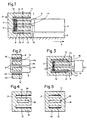
- the drive device 1 shows an electromagnetic cross-section in a representation that is not to scale Drive device 1.
- the drive device 1 consists of a stator 2 and one with the stator 2 non-contact cooperating coil 3.
- the coil 3 has a coil body 4, which with a on a horizontally arranged sliding plate 5 sliding working member 6 is rigidly connected.
- the Work organ 6 carries, for example, the wire head bonder, not shown.
- the work organ 6 is preferably approximated by an air bearing preloaded on the sliding plate 5 stored smoothly.
- one in two can also be used orthogonal directions x and y movable table can be provided, in which case the upper plate of the Table is firmly connected to the bobbin 4.
- the drive device 1 serves to drive the Work organ 6 in the x direction.
- the coil 3 is according to the teaching of the Swiss patent CH 678 907 designed so that it is also in the horizontal y direction orthogonal to the x direction is movable.
- the stator 2 is essentially E-shaped in cross section.
- the stator 2 has one vertical web 7 and three spaced horizontal webs 8-10
- a first air gap 11 is formed between the upper web 8 and the middle web 9
- a second air gap 12 is formed between the middle web 9 and the lower web 8.
- the Windings of the coil 3 run through these two air gaps 11 and 12.
- At the air gaps 11, 12 associated sides of the webs 8 and 10 are magnets 13 which are known with the coil 3 Cooperate wisely.
- the central web 9 of the stator 2 has an opening that is open towards the working element 6 Gap 14.
- a web 15 connected to the coil former 4 is located in the gap 14.
- the web 15 connects the two perpendicular side walls of the bobbin 4 and increases the Rigidity of the bobbin 4.
- the web 15 is also with the wall facing the working element 6 of the bobbin 4 connected.
- the web 15 is only shown schematically. In the simplest design, the web 15 is a plate.
- the web 15 is preferably a profiled three-dimensional Body that is shaped in such a way that it is as light as possible is as stable as possible.
- the gap 14 allows the mechanical stability of the connecting element that the coil 3 with connects the working organ 6, to increase significantly by the additional web 15 or, at given stability to significantly reduce the weight of the connecting element. In particular can thereby reinforce the coil body 4 in the area of the turns of the coil 3 and thereby the Stiffness of the coil 3 can be increased without much weight gain.
- the web 15 can be wider than Heatsink, for example with cooling fins, be formed so that the drive in the coil 3rd resulting heat can be better dissipated to the surrounding air.
- FIG. 2 shows the stator 2 in cross section along the line A-A of FIG. 1.
- the web 15 projects laterally, i.e. in a direction transverse to the drive direction, out of the gap 14 and with the side walls 4a of the bobbin 4 connected.
- FIG. 3 shows a drive device 1 designed as a voice coil motor with a stator 2, at which the two air gaps 11, 12 on the side facing the working member 6 by further webs 16 and 17 are closed.
- FIGS. 4 and 5 show embodiments in which the gap 14 against the working member 6 does not open, but is closed by a web 18: the gap 14 becomes a slot 19.
- the web 18 increases the mechanical stability of the stator 2 and prevents its tendency to vibrate, he but prevents a direct connection of the web 15 to the working element 6.
Landscapes
- Engineering & Computer Science (AREA)
- Physics & Mathematics (AREA)
- Chemical & Material Sciences (AREA)
- Combustion & Propulsion (AREA)
- Electromagnetism (AREA)
- Power Engineering (AREA)
- Reciprocating, Oscillating Or Vibrating Motors (AREA)
- Linear Motors (AREA)
Abstract
Description
- Fig. 1, 2
- den Stator einer elektromagnetischen Antriebsvorrichtung im Querschnitt, und
- Fig. 3 - 5
- weitere Ausführungsbeispiele des Stators.
Claims (3)
- Elektromagnetische Antriebsvorrichtung zum Antrieb eines Arbeitsorganes (6), mit einem Stator (2) und einer mit dem Stator (2) berührungsfrei zusammenwirkenden Spule (3), wobei der Stator (2) einen senkrechten Steg (7) und drei im Abstand zueinander angeordnete, horizontal verlaufende Stege (8, 9, 10) aufweist und wobei die Spule (3) einen mit dem Arbeitsorgan verbindbaren Spulenkörper (4) aufweist, dadurch gekennzeichnet, dass der mittlere Steg (9) des Stators (2) einen gegen das Arbeitsorgan (6) hin offenen Spalt (14) oder einen Schlitz (19) aufweist und dass sich im Spalt (14) bzw. Schlitz (19) ein Steg (15) befindet, der in einer Richtung quer zur Antriebsrichtung aus dem Spalt (14) bzw. Schlitz (19) herausragt und mit dem Spulenkörper (4) verbunden ist.
- Antriebsvorrichtung nach Anspruch 1, dadurch gekennzeichnet, dass der mit dem Spulenkörper (4) verbundene Steg (15) starr mit Seitenwänden (4a) des Spulenkörpers (4) verbunden ist.
- Wire Bonder mit mindestens einer elektromagnetischen Antriebsvorrichtung nach Anspruch 1 oder 2.
Priority Applications (2)
| Application Number | Priority Date | Filing Date | Title |
|---|---|---|---|
| EP00810036A EP1024587A3 (de) | 1999-01-26 | 2000-01-17 | Elektromagnetische Antriebsvorrichtung |
| SG200000411A SG115333A1 (en) | 1999-01-26 | 2000-01-21 | Electromagnetic drive device |
Applications Claiming Priority (3)
| Application Number | Priority Date | Filing Date | Title |
|---|---|---|---|
| EP99810058A EP1024588A1 (de) | 1999-01-26 | 1999-01-26 | Elektromagnetische Antriebsvorrichtung |
| EP99810058 | 1999-01-26 | ||
| EP00810036A EP1024587A3 (de) | 1999-01-26 | 2000-01-17 | Elektromagnetische Antriebsvorrichtung |
Publications (2)
| Publication Number | Publication Date |
|---|---|
| EP1024587A2 true EP1024587A2 (de) | 2000-08-02 |
| EP1024587A3 EP1024587A3 (de) | 2003-11-19 |
Family
ID=26073752
Family Applications (1)
| Application Number | Title | Priority Date | Filing Date |
|---|---|---|---|
| EP00810036A Withdrawn EP1024587A3 (de) | 1999-01-26 | 2000-01-17 | Elektromagnetische Antriebsvorrichtung |
Country Status (2)
| Country | Link |
|---|---|
| EP (1) | EP1024587A3 (de) |
| SG (1) | SG115333A1 (de) |
Cited By (1)
| Publication number | Priority date | Publication date | Assignee | Title |
|---|---|---|---|---|
| WO2005013464A1 (en) * | 2003-08-01 | 2005-02-10 | Koninklijke Philips Electronics N.V. | 2-dimensional displacement device |
Family Cites Families (6)
| Publication number | Priority date | Publication date | Assignee | Title |
|---|---|---|---|---|
| DE2217958A1 (de) * | 1972-04-14 | 1973-10-25 | Chodschajanc | Magnetsystem fuer schwingankermotore |
| US4439699A (en) * | 1982-01-18 | 1984-03-27 | International Business Machines Corporation | Linear moving coil actuator |
| JPS60156261A (ja) * | 1984-01-25 | 1985-08-16 | Matsushita Electric Ind Co Ltd | 複合モ−タ |
| JPS61191256A (ja) * | 1985-02-20 | 1986-08-25 | Canon Inc | ボイスコイル型リニアモ−タ |
| US4731919A (en) * | 1986-10-28 | 1988-03-22 | Hr Textron, Inc. | Centering mechanism for moving coil force motor |
| EP0317787B2 (de) * | 1987-11-25 | 1997-05-07 | Esec Sa | Einrichtung zur Durchführung der Zustellbewegung eines Arbeitsorgans zu einer Arbeitsstation |
-
2000
- 2000-01-17 EP EP00810036A patent/EP1024587A3/de not_active Withdrawn
- 2000-01-21 SG SG200000411A patent/SG115333A1/en unknown
Cited By (1)
| Publication number | Priority date | Publication date | Assignee | Title |
|---|---|---|---|---|
| WO2005013464A1 (en) * | 2003-08-01 | 2005-02-10 | Koninklijke Philips Electronics N.V. | 2-dimensional displacement device |
Also Published As
| Publication number | Publication date |
|---|---|
| SG115333A1 (en) | 2005-10-28 |
| EP1024587A3 (de) | 2003-11-19 |
Similar Documents
| Publication | Publication Date | Title |
|---|---|---|
| EP0637559B1 (de) | Vibrations-Linear-Förderer | |
| DE69814134T2 (de) | Führungsschuh für aufzug | |
| EP0296459A1 (de) | Ständer für eine Textilmaschine, insbesondere für eine Spinn- oder Zwirnmaschine | |
| DE20312304U1 (de) | Schublade | |
| EP1024588A1 (de) | Elektromagnetische Antriebsvorrichtung | |
| DE9402427U1 (de) | Aufzugsystem mit Linearantrieb | |
| DE9313426U1 (de) | Lüftungsvorrichtung für Räume | |
| EP1194359B1 (de) | Seilzug-aufzuganlage | |
| AT389862B (de) | Gegengewichts-baugruppe fuer aufzugsanlagen | |
| DE102004050869A1 (de) | Randprofil eines Wandelements | |
| EP1453698A1 (de) | Haltenetz zur anbringung an flächen im innen- und/oder kofferraum von kraftfahrzeugen | |
| EP0744141B1 (de) | Möbelelement für ein Möbelanbausystem | |
| EP0648450A1 (de) | Tischplattenelement und Tischplattenkombination für Bürotische | |
| DE102020101708A1 (de) | Befestigungsvorrichtung und Fassade | |
| DE812832C (de) | Mauerstein | |
| DE3702298C2 (de) | ||
| DE4041420A1 (de) | Geradefuehrung mit geringer bauhoehe | |
| EP0455973A1 (de) | Führungsleiste für Aufzugstür | |
| EP1296883A1 (de) | Aufzug mit einem linearmotorantrieb | |
| DE10135389A1 (de) | C-Profil | |
| DE19836171B4 (de) | Fertigteilsatz zur Errichtung eines Gebäudes | |
| EP0561390A1 (de) | Elektroinstallationsbaustein | |
| DE102006022430A1 (de) | Gebäudedecke mit Tilger | |
| DE3933072A1 (de) | Profilschiene als bauelement fuer den moebel- und gestellbau | |
| DE3206865C2 (de) | Vorhangschienenträgeranordnung |
Legal Events
| Date | Code | Title | Description |
|---|---|---|---|
| PUAI | Public reference made under article 153(3) epc to a published international application that has entered the european phase |
Free format text: ORIGINAL CODE: 0009012 |
|
| AK | Designated contracting states |
Kind code of ref document: A2 Designated state(s): AT BE CH CY DE DK ES FI FR GB GR IE IT LI LU MC NL PT SE |
|
| AX | Request for extension of the european patent |
Free format text: AL;LT;LV;MK;RO;SI |
|
| RAP1 | Party data changed (applicant data changed or rights of an application transferred) |
Owner name: ESEC TRADING SA |
|
| PUAL | Search report despatched |
Free format text: ORIGINAL CODE: 0009013 |
|
| AK | Designated contracting states |
Kind code of ref document: A3 Designated state(s): AT BE CH CY DE DK ES FI FR GB GR IE IT LI LU MC NL PT SE |
|
| AX | Request for extension of the european patent |
Extension state: AL LT LV MK RO SI |
|
| AKX | Designation fees paid | ||
| REG | Reference to a national code |
Ref country code: DE Ref legal event code: 8566 |
|
| STAA | Information on the status of an ep patent application or granted ep patent |
Free format text: STATUS: THE APPLICATION IS DEEMED TO BE WITHDRAWN |
|
| 18D | Application deemed to be withdrawn |
Effective date: 20040803 |