EP1024573A2 - Procédé et dispositif pour déterminer la décharge partielle dans un appareillage à isolation par gaz - Google Patents
Procédé et dispositif pour déterminer la décharge partielle dans un appareillage à isolation par gaz Download PDFInfo
- Publication number
- EP1024573A2 EP1024573A2 EP00101011A EP00101011A EP1024573A2 EP 1024573 A2 EP1024573 A2 EP 1024573A2 EP 00101011 A EP00101011 A EP 00101011A EP 00101011 A EP00101011 A EP 00101011A EP 1024573 A2 EP1024573 A2 EP 1024573A2
- Authority
- EP
- European Patent Office
- Prior art keywords
- partial discharge
- signal
- diagnostic
- gas
- diagnosis
- Prior art date
- Legal status (The legal status is an assumption and is not a legal conclusion. Google has not performed a legal analysis and makes no representation as to the accuracy of the status listed.)
- Granted
Links
Images


Classifications
-
- H—ELECTRICITY
- H02—GENERATION; CONVERSION OR DISTRIBUTION OF ELECTRIC POWER
- H02B—BOARDS, SUBSTATIONS OR SWITCHING ARRANGEMENTS FOR THE SUPPLY OR DISTRIBUTION OF ELECTRIC POWER
- H02B5/00—Non-enclosed substations; Substations with enclosed and non-enclosed equipment
- H02B5/06—Non-enclosed substations; Substations with enclosed and non-enclosed equipment gas-insulated
-
- G—PHYSICS
- G01—MEASURING; TESTING
- G01R—MEASURING ELECTRIC VARIABLES; MEASURING MAGNETIC VARIABLES
- G01R31/00—Arrangements for testing electric properties; Arrangements for locating electric faults; Arrangements for electrical testing characterised by what is being tested not provided for elsewhere
- G01R31/12—Testing dielectric strength or breakdown voltage ; Testing or monitoring effectiveness or level of insulation, e.g. of a cable or of an apparatus, for example using partial discharge measurements; Electrostatic testing
- G01R31/1227—Testing dielectric strength or breakdown voltage ; Testing or monitoring effectiveness or level of insulation, e.g. of a cable or of an apparatus, for example using partial discharge measurements; Electrostatic testing of components, parts or materials
- G01R31/1254—Testing dielectric strength or breakdown voltage ; Testing or monitoring effectiveness or level of insulation, e.g. of a cable or of an apparatus, for example using partial discharge measurements; Electrostatic testing of components, parts or materials of gas-insulated power appliances or vacuum gaps
-
- H—ELECTRICITY
- H02—GENERATION; CONVERSION OR DISTRIBUTION OF ELECTRIC POWER
- H02H—EMERGENCY PROTECTIVE CIRCUIT ARRANGEMENTS
- H02H1/00—Details of emergency protective circuit arrangements
- H02H1/0007—Details of emergency protective circuit arrangements concerning the detecting means
- H02H1/0015—Using arc detectors
-
- H—ELECTRICITY
- H02—GENERATION; CONVERSION OR DISTRIBUTION OF ELECTRIC POWER
- H02H—EMERGENCY PROTECTIVE CIRCUIT ARRANGEMENTS
- H02H1/00—Details of emergency protective circuit arrangements
- H02H1/0092—Details of emergency protective circuit arrangements concerning the data processing means, e.g. expert systems, neural networks
Definitions
- the present invention relates to a method of diagnosing a partial discharge in a gas-insulated apparatus and a partial discharge diagnosing system for carrying out the same. More particularly, the present invention relates to a method of diagnosing a partial discharge in a gas-insulated apparatus by detecting a partial discharge signal, and subjecting the partial discharge signal to multiple stages of conditional branching for diagnosis, and a partial discharge diagnosing system for carrying out the method.
- a gas-insulted apparatus such as a gas-insulated switchgear installed in a substation, produces a partial discharge when an abnormal insulation condition arises in the apparatus.
- the partial discharge generates electromagnetic waves therewith.
- the partial discharge which can be regarded as a precursory indication of an accidental electric breakdown, must accurately be detected and diagnosis must be made on the partial discharge to decide whether or not there is any abnormal insulation condition to prevent the accidental electric breakdown of the gas-insulated apparatus.
- Causes of abnormal insulation include the entrance of metallic foreign matters into the gas-insulated apparatus, defects in insulators, such as voids or cracks in spacers, faulty contact in conductors of shielding members and or the like.
- the insulator is progressively deteriorated and there is the possibility that electric breakdown will occur when an overvoltage, such as a lightning, is applied to the gas-insulated apparatus. Therefore, a part where the partial discharge occurred, the level of the partial discharge must accurately be determined and the part where the partial discharge occurred must be inspected and repaired depending on the part and the level of the partial discharge occurred.
- Detection of the partial discharge can be performed through the detection of an electromagnetic wave, a high-frequency current, a vibration or a sound that is generated along with the partial discharge, or through the analysis of a gas that is produced by the partial discharge.
- a partial discharge that is produced in SF 6 gas contained in the gas-insulated apparatus exhibits a very sharp pulse discharge having a pulse width in the range of several nanoseconds to several tens nanoseconds.
- the electromagnetic wave generated along with the partial discharge has a frequency in a wide frequency band up to several gigahertz.
- the gas-insulated apparatus is constructed by sealing components in a metal container and, similar to a waveguide, propagates electromagnetic waves efficiently. Since the components of the gas-insulated apparatus are contained in the metal container, it is relatively difficult for external electromagnetic noise to reach the component parts. Accordingly, electromagnetic waves generated along with the partial discharge can be detected in a high sensitivity by disposing an internal antenna in the metal container.
- a previously proposed method of finding a part where a partial discharge occurred receives electromagnetic waves of frequencies with a wide frequency band of several megahertz to several gigahertz by an internal antenna and analyzes the frequency of the electromagnetic waves by a spectrum analyzer or the like.
- Another previously proposed diagnostic method receives an electromagnetic wave of a specific frequency that is not affected by external noise or electromagnetic waves of frequencies with a narrow frequency band, instead of receiving all the electromagnetic waves of frequencies in a wide frequency band.
- JP-B No. Hei 7-50147 there have been proposed a method that analyzes detected electromagnetic waves for frequency and decides whether or not any abnormal condition has occurred on the basis of the levels of frequency of the electromagnetic waves, and a method that decides whether or not any abnormal condition has occurred on the basis of feature values computed from the patterns of waveforms.
- a known deciding means achieves pattern recognition by using a neural network or a fuzzy system.
- the neural network comprises an input layer, an intermediate layer and an output layer, a plurality of frequency data are given to the input layer, and diagnostic results are provided on the output layer.
- the known method of detecting a partial discharge signal decides that a partial discharge has occurred when a signal of a level not lower than a predetermined level, having a frequency in a reference frequency band for decision is generated. It is difficult for this method to discriminate clearly a partial discharge signal from an external noise signal. If the external noise signal is produced steadily, such as a broadcast wave, the external noise signal is measured beforehand, and signals of frequencies outside a frequency band including the frequency of the external noise signal are measured or the external noise signal is removed by a noise signal removing process. However, if the external noise signal is generated unsteadily, such as a communication signal transmitted by a mobile telephone, noise from devices or an aerial corona noise, it is difficult to discriminate a partial discharge signal generated by an internal partial discharge from the external noise.
- the frequency characteristic of the partial discharge signal detected by the antenna is affected by the frequency characteristic of a sensor including the antenna, and the frequency characteristic of an electromagnetic wave propagating passage determined by the shape and construction of a tank included in the gas-insulated apparatus. Consequently, it is difficult to accurately determine whether the signal detected by the antenna is a partial discharge signal generated internally or externally, and specialist's diagnosis is necessary for the decision.
- the neural network structure employed in the known back propagation method makes diagnosis immediately upon the reception of analytic data and provides results of analysis.
- the input layer 41 and the output layer 43 each has a large number of nodes, making the internal configuration of the neural network structure complicated, there rise problems such that the convergence of the learning of known data is difficult, local minimum is liable to occur and an enormously long learning time is necessary. Furthermore, it is difficult to achieve diagnosis with a practically acceptable accuracy.
- the present invention has been made in view of the foregoing problems and it is therefore an object of the present invention to provide a diagnostic system capable of detecting a partial discharge signal acting as a precursory signal indicating an accidental electric breakdown in a gas-insulated apparatus and of achieving accurate diagnosis through multiple conditional branching of the partial discharge signal, and a partial discharge diagnosing method to be carried out therein.
- the present invention employs the following means to solve the foregoing problems.
- the diagnostic unit is provided with a diagnostic means for examining a frequency spectrum of the partial discharge signal.
- the frequency spectrum shows discrete values in each frequency divisions obtained by dividing the frequency band at predetermined intervals.
- the diagnostic unit is provided with a diagnostic means for diagnosing feature values of a frequency spectrum of the partial discharge signal.
- the diagnostic unit is provided with a diagnostic means for diagnosing periodic component signals synchronous with a phase of a system frequency.
- the periodic component signals synchronous with the phase of the system frequency are discrete values in divisions determined by dividing one period of the system frequency at predetermined angular intervals.
- the diagnostic unit is provided with a diagnostic means for diagnosing feature values of periodic component signals synchronous with the phase of the system frequency.
- the first and the second diagnostic means analyze different kinds of analytic signals, respectively.
- the signal to be examined is defined as standards with a maximum value.
- the diagnostic unit employs a neural network.
- the neural network receives a signal again and carries out diagnosis again when an output of the neural network is less than 0.5.
- the diagnostic unit employs a fuzzy system.
- a method of diagnosing a partial discharge produced in a gas-insulated apparatus comprises the steps of: detecting a partial discharge signal representing a partial discharge and produced by the gas-insulated apparatus by a partial discharge signal detector; receiving the partial discharge signal detected by the partial discharge detector and analyzing the partial discharge signal by a signal analyzer; determining a cause of the partial discharge on the basis of results of analysis made by the signal analyzer, provided with a diagnostic means for multiple conditional branching by a diagnostic unit; and displaying results of diagnosis on a display unit; wherein the diagnostic unit is provided with diagnostic means that carries out multiple stage conditional branching, the diagnostic means makes conditional branching to one of a plurality of second diagnostic means according to result of diagnosis made by a first diagnostic means, and obtains the results of diagnosis sequentially made by the second diagnostic means, the diagnostic means executes first a diagnostic operation for discriminating the partial discharge signal detected by the partial discharge signal detector between the partial discharge signal produced in the gas-insulated apparatus and the external noise
- the diagnostic means carries out a diagnostic operation for deciding whether the partial discharge signal is a partial discharge signal produced in a gas included in the gas-insulated apparatus or a partial discharge signal produced in an insulator included in the gas-insulated apparatus.
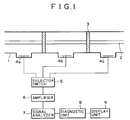
- FIG. 1 is a block diagram of a partial discharge diagnosing system in a preferred embodiment according to the present invention for diagnosing a partial discharge produced in a gas-insulated apparatus
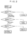
- Fig. 2 is a flowchart of a diagnostic procedure using conditional branching to be carried out by the partial discharge diagnosing system shown in Fig. 1.
- a grounded metal container 1 included in a gas-insulated apparatus a high-tension conductor 2, insulating spacers 3 holding the high-tension conductor 2, and partial discharge signal detectors 4a, 4b and 4c for detecting electromagnetic waves generated along with a partial discharge, a broad-band selector switch 5 for selecting one of the partial discharge signal detectors 4a, 4b and 4c, an amplifier 6, a signal analyzer 7, such as a spectrum analyzer for frequency analysis or a FFT (fast Fourier transform) analyzer for analyzing signals provided by a digital storage scope, a diagnostic unit 8 composed of such as a personal computer for diagnosing causes of the partial discharge and noise types, and a display unit 9 for displaying results of diagnosis.
- the partial discharge signal detectors 4a, 4b and 4c may be used as detecting antennas or internal electrodes included in the gas-insulated apparatus.
- a detection signal provided by the partial discharge signal detector is transferred through the broad-band selector switch 5 and the amplifier 6 to the signal analyzer 7.
- the signal analyzer 7 processes the detection signal for signal analysis, such as frequency analysis.
- the diagnostic unit 8 receives data from the signal analyzer 7 and carries out a diagnostic procedure to determine the cause of a partial discharge and the type of noise. Results of diagnosis are displayed on the display unit 9.
- the partial discharge diagnosing system is able to accomplish the diagnosis in a very short time and to achieve the diagnosis of abnormal conditions occurred in the gas-insulated apparatus through automatic monitoring.
- the signal analyzer 7 such as a spectrum analyzer, analyzes a signal received from the partial discharge detectors 4a, 4b and 4c incorporated into the gas-insulated apparatus.
- a partial discharge is diagnosed by subjecting the analyzed partial discharge signal to diagnostic steps 1 to 3 for conditional branching.
- diagnostic step 1 data of an analyzed background noise signal (analyzed BGN signal) representing background noise generated in a state where any partial discharge is not produced is prepared beforehand. Then, the data of the analyzed BGN signal is compared with data obtained by analyzing a partial discharge signal to decide whether or not any partial discharge has been produced. For example, when the analyzed partial discharge data is greater than the analyzed BGN data, it is decided that a partial discharge has been produced. If it is decided in the diagnostic step 1 that a partial discharge has been produced, the diagnostic step 2 is executed. If it is found that any partial discharge has not been produced and the gas-insulated apparatus is operating normally, information is displayed to that effect on the display unit.
- analyzed BGN signal analyzed background noise signal
- a diagnosis is made to decide whether the detected partial discharge signal has been induced by an internal cause or by an external cause. If it is decided that the partial discharge signal has been produced due to an internal cause, the diagnostic step 3 is executed. If it is decided that the partial discharge signal has been produced due to an external cause, the information is displayed to the effect that the partial discharge signal is caused by external noise on the display unit.
- a diagnosis is made to decide whether the detected partial discharge signal represents a partial discharge that occurred in the gas-insulated apparatus or a partial discharge caused by the faulty contact of a shield or the like. If it is decided that the partial discharge signal represents a partial discharge that occurred in the gas-insulated apparatus, information is displayed to the effect that the partial discharge is an internal discharge. If it is decided that the partial discharge signal represents a discharge caused by faulty contact, information is displayed to the effect that the partial discharge is caused by faulty contact.
- the partial discharge signal is subjected to multiple conditional branching, to thereby achieve accurate diagnosis.
- Fig. 3 shows a neural network that can be used in the diagnostic unit.
- the neural network is of a three-layer structure consisting of an input layer 11, an intermediate layer 12 and an output layer 13.
- Input data x1 to xm are given to the input layer 11.
- the input data x1 to xm may be the respective signal intensities of each one of frequency bands in a frequency spectrum or the respective signal intensities of bands obtained by dividing one period of a system frequency at predetermined angular intervals.
- Results of diagnosis are provided on the output layer 13. Diagnosis can be made on the basis of output data y 1 and y 2 provided in the output layer 13.
- the output layer 13 has a small number of units to achieve quick diagnosis through a small number of branching operations; that is, an accurate decision can quickly be wade by using about two branching conditions to simplify the structure of the neural network for individual diagnosis. Learning time can greatly be curtailed and learning can easily be converged.
- the reduction in the number of units of the output layer brings about the reduction of the number of units of the intermediate layer 12, and hence the neural network with number of the units of the entire network reduced can be obtained.
- Fig. 4 is a flowchart of another diagnostic procedure including conditional branching steps to be carried out by the partial discharge diagnosing system shown in Fig. 1.
- a signal received from the partial discharge detector 4 incorporated into the gas-insulated apparatus is analyzed by the signal analyzer, such as a spectrum analyzer.
- a partial discharge signal is analyzed by diagnostic steps 1 to 14 for conditional branching.
- analyzed BGN signal Data of an analyzed background noise signal (analyzed BGN signal) is prepared beforehand.
- the analyzed BGN data is compared with data obtained by analyzing a partial discharge signal to decide whether or not any partial discharge has been produced. For example, when the analyzed partial discharge data is greater than the analyzed BGN data, it is decided that a partial discharge has been produced. If it is decided in the diagnostic step 1 that a partial discharge has been produced, the diagnostic step 2 is executed. If it is found that any partial discharge has not been produced and the gas-insulated apparatus is operating normally, or if not the partial discharge, but noise has been generated, information is displayed to the effect that the gas-insulated apparatus is normal on the display unit.
- a diagnosis is made to decide whether the detected partial discharge signal is the partial discharge signal produced in the gas-insulated apparatus, or the signal induced by noise due to the faulty contact of a shield or the like, or the signal induced due to an aerial corona discharge produced outside a tank of the gas-insulated apparatus. If it is decided that the partial discharge signal has been produced by an aerial corona discharge or the like, the diagnostic step 3 is executed. If it is decided that the partial discharge signal has been generated due to a partial discharge occurred in the gas-insulated apparatus, the diagnostic step 4 is executed.
- diagnosis is made to decide whether the detected partial discharge signal represents a condition created by the faulty contact of the shield or the like, or a condition created by an aerial corona discharge produced outside the tank of the gas-insulated apparatus.
- diagnosis is made to decide whether the detected partial discharge signal has been produced due to an abnormal condition due to the insulating gas system or an abnormal condition due to the insulating system. If it is decided that the partial discharge signal represents an abnormal condition created by the insulating gas system, the diagnostic step 9 is executed. If it is decided that the partial discharge signal represents an abnormal condition created by the insulating system, the diagnostic step 5 is executed.
- diagnosis is made to decide whether the detected partial discharge signal represents a condition created by a defect in a spacer or a condition created by a defect in a built-in capacitor.
- the diagnostic step 6 is executed.
- diagnosis is made to decide whether or not the detected partial discharge signal represents a condition created by foreign matters on the spacer. If it is decided that the partial discharge signal represents a condition created by a cause other than foreign matters on the spacer, the diagnostic step 7 is executed.
- diagnosis is made to decide whether the partial discharge signal represents a condition created by cracks in the insulator, a condition created by exfoliation in the insulator or a condition created by voids in the insulator.
- diagnosis is made to decide whether the detected partial discharge signal represents a condition created by cracks in the insulator or a condition created by exfoliation in the insulator.
- diagnosis is made to decide whether the detected partial discharge signal represents a condition created by stationary foreign matters contained in the insulating gas or a condition created by metallic foreign matters floating in the insulating gas. If it is decided that the partial discharge signal represents a condition created by stationary foreign matters, the diagnostic step 10 is executed.
- diagnosis is made to decide whether the detected partial discharge signal represents a condition created by a projection formed in the insulating gas or a condition created by metallic foreign matters floating in the insulating gas. If it is decided that the partial discharge signal represents a condition created by a projection formed in the insulating gas or metallic foreign matters floating in the insulating gas, the diagnostic step 11 is executed.
- diagnosis is made to decide whether the detected partial discharge signal represents a condition created by foreign matters lying on the conductor.
- diagnosis is made to decide whether or not the detected partial discharge signal was generated by external noise. If it is decided that the partial discharge signal was generated by external noise, the diagnostic step 13 is executed.
- diagnosis is made to decide whether the detected partial discharge signal represents a broadcast wave or nonsteady-state noise. If it is decided that the partial discharge signal is a nonsteady-state noise, the diagnostic step 14 is executed.
- diagnosis is made to decide whether the detected partial discharge signal is a signal generated by a mobile telephone or other noise signal.
- the causes of abnormal conditions are determined through conditional branching in the diagnostic steps 1 to 14. Since each diagnostic step has two branches, the diagnostic operation is simple and accurate diagnosis can be achieved.
- Diagnosing accuracy is improved by providing conditional branching for examining characteristic patterns of signals in early diagnostic steps. That is, the noise signal whose characteristic is greatly different from the partial discharge signal is examined in the diagnostic step 1, the signal produced by faulty contact or aerial corona discharge is examined in the diagnostic step 2, and the diagnosis to decide whether the signal is produced by an abnormal condition in the spacer or by an abnormal condition in the built-in capacitor is executed in the diagnostic step 5. Accordingly, the final accuracy of the diagnosis of the partial discharge signal is improved by executing conditional branching or significant causes in the initial stage of diagnosis.
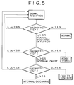
- Fig. 5 is a flowchart of a diagnostic procedure to be carried out by the neural network for rediagnosis.
- analyzed background noise signal representing background noise is prepared beforehand as data of a partial discharge signal.
- the data of analyzed BGN signal is compared with data of an actually received partial discharge signal to decide whether or not any partial discharge has been produced. For example, when the data of the analyzed partial discharge signal is greater than the data of the analyzed BGN signal, it is decided that a partial discharge has been produced.
- the neural network needs to decide that its output is true, only when an output provided on one of its output units is greater than a predetermined value. In other words, when an output value yn provided on the output unit in the diagnostic step 1 satisfies yn > 0.5, it is decided that yn is true.
- the diagnostic step 1 of Fig. 5 it is decided that the condition is normal when y1 > 0.5 and a partial discharge signal has been detected when y2 > 0.5, followed by the execution of diagnostic step 2.
- y1 ⁇ 0.5 and y2 ⁇ 0.5 it is decided that definite diagnosis is impossible and a signal is received again for rediagnosis.
- a decision is made on the basis of a criterion that a maximum value among the outputs from the output unit is true, so that a decision is made even if the outputs on the output unit are nearly zero, or, even if the input date is greatly different from the data obtained by learning.
- a definite diagnosis is impossible when y 1 ⁇ 0.5 and y 2 ⁇ 0.5 and a signal is received again for rediagnosis to avoid making a wrong decision.
- the analyzed data for diagnosis will be described.
- the analyzed data for diagnosis can be provided by the signal analyzer 7.
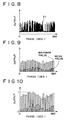
- Fig. 6 shows a frequency spectrum produced by analyzing the partial discharge signal produced in the gas-insulated apparatus by the spectrum analyzer.
- frequency data measured on the horizontal axis appear at several hundreds points. Therefore, it will take much time for learning and it is possible that learning does not converge if all the frequency data is given to the neural network for diagnosis.
- Fig. 7 is a graph obtained by dividing the frequency band of frequency spectrum shown in Fig. 6, 0 to 1500 MHz at each 75 MHz into 20 divisions, and superposing a bar graph of the mean value and the maximum value in each frequency divisions.
- the amount of the analyzed data can be reduced without changing the pattern of the frequency spectrum by producing the analyzed data by thus dividing the frequency range into frequency divisions and calculating the mean value and the maximum value of the frequency divisions.
- the difference between signals due to variation of the partial discharge phenomenon can be reduced by reducing the amount of the data and accurate diagnosis can be achieved.
- Fig. 8 is a graph showing a pattern of the signal intensity of a periodic component synchronous with the phase of a system frequency.
- the partial discharge phenomenon that occurs in the gas-insulated apparatus is dependent on the amplitude of an applied AC voltage. Therefore, each partial discharge has phase characteristics specific to the causes of the partial discharges. Therefore, the partial discharge signal can be discriminated from the noise signal and causes of the partial discharge signal can be determined by analyzing the signal intensity of the periodic component synchronous with the phase of the system frequency for each phase.
- Fig. 9 is a graph obtained by dividing one period (0° to 360°) of an applied ac voltage in the graph of signal intensities of periodic components synchronous with the phase of the system frequency shown in Fig. 8 at each 18° into 20 divisions, and superposing a bar graph of the mean value and the maximum value in each divisions.
- the amount of the analyzed data can be reduced without changing the pattern of the signal intensities of the periodic components synchronous with the phase of the system frequency by calculating the mean value and the maximum value of the phase divisions by thus dividing the phase into phase divisions.
- the difference between signals due to variation of the partial discharge phenomenon can be reduced by reducing the amount of the data and accurate diagnosis can be achieved.
- Fig. 10 is a bar graph obtained by defining a pattern of signal intensities of periodic components synchronous with the phase of the system frequency as standards with a maximum signal intensity.
- the frequency pattern and a feature pattern can be defined as standards.
- signal intensity patterns are defined as standards with their maximum values as shown in Fig. 10 to eliminate the difference between the signals due to difference in signal attenuation, signal intensity patterns of partial discharge signals indicating partial discharges caused by the same cause are not taken to be those indicating partial discharges caused by different causes, respectively.
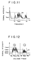
- Fig. 11 is a graph showing feature values extracted from a frequency spectrum obtained by measuring a partial discharge signal by a spectrum analyzer.
- Ymax is the value of the maximum signal intensity
- Yave is the value of the average signal intensity
- fmax is a frequency corresponding to the maximum signal intensity Ymax
- fs and fe are frequencies in a low-frequency range and a high-frequency range in a spectrum produced on a high-frequency side, respectively.
- Fig. 12 is a graph showing feature values extracted from a signal intensity pattern of periodic components synchronous with the phase of a system frequency.
- Umax+ is a maximum value of signal intensity in a positive half wave
- Umax- is a maximum value of signal intensity in a negative half wave
- Uave+ is the average value of signal intensity in the positive half wave
- Uave- is the average value of signal intensity of the negative half wave
- ⁇ s+ and ⁇ s- are the phase angles of the leading edges of the positive half wave signal waveform and the negative half wave signal, respectively
- ⁇ e+ and ⁇ e- are the phase angles of the trailing edges of the positive half wave signal waveform and the negative half wave signal, respectively
- ⁇ max+ and ⁇ max- are phase angles corresponding to the maximum signal intensities in the positive half wave signal waveform and the negative half wave signal, respectively.
- Figs. 11 and 12 roughly show the signal intensity patterns of a partial discharge in the range of 0 to 1500 MHz produced when a fixed foreign matter, such as a projection, lies on the high-tension conductor of the gas-insulated apparatus.
- the partial discharge signal is concentrated on regions around peaks in the positive and the negative half wave.
- the pattern shown in Fig. 12 assumes the typical features of a partial discharge signal indicating a partial discharge caused by a defect in the gas system.
- the feature values shown in Figs. 11 and 12 are more conspicuous for detecting a fixed foreign matter, such as a projection on the high-tension conductor of the gas-insulated apparatus than the patterns of frequency spectrum or the signal intensity of the periodic components synchronous with the phase of the system frequency.
- the use of those feature values improves the accuracy of diagnosis.
- the feature values are extracted from parameters indicating the intensity, the frequency and the phase of the partial discharge signal.
- Other feature values representing the shape of the partial discharge signal pattern, such as the skewness and the sharpness of the partial discharge signal pattern, or coefficient of correlation in the positive and the negative half wave may be used as data for analysis.
- the feature values of the partial discharge signal include those specific to the cause of the partial discharge and those dependent on the measuring conditions, such as applied voltage, ambient conditions including the pressure of the gas. For example, the number of times to cause the partial discharge, the intensity and the starting phase of a partial discharge caused by a projection formed on the high-tension conductor changes as the applied voltage rises. On the other hand, the voltage phase of the maximum discharge intensity and the average phase in which the discharge is produced are scarcely dependent on the applied voltage. Accordingly, the accuracy of diagnosis can be improved by using feature values independent of measuring conditions as data for analysis.
- a diagnostic system can be constructed by using the feature values thus extracted as input data for a fuzzy system or a neural network.
- Fig. 13 is a flowchart of another diagnostic procedure to be carried out by the partial discharge diagnosing system.
- Diagnosis is carried out in a diagnostic step 1 by using frequency analyzing data obtained by analyzing a frequency spectrum (frequency pattern). Background noise data (BGN data) representing background noise is prepared beforehand.
- BGN data Background noise data
- the BGN data is compared with an partial discharge data obtained by analyzing a partial discharge signal to decide whether or not any partial discharge has been produced. For example, when the partial discharge data is greater than the BGN data, it is decided that a partial discharge has been produced. If it is decided in the diagnostic step 1 that a partial discharge has been produced, a diagnostic step 2 is executed. If any partial discharge has not been produced and the gas-insulated apparatus is operating normally, information is displayed to that effect on the display unit.
- diagnosis is made by using data obtained by analyzing the signal intensity pattern (phase pattern) of periodic components synchronous with the phase of a system frequency to decide whether the partial discharge signal indicates a condition created by an internal cause or an external cause. If it is decided that the partial discharge signal indicates a condition created by an internal cause, a diagnostic step 3 is executed. If it is decided that the partial discharge signal indicates a condition created by an external cause, information is displayed to the effect that the partial discharge signal is caused by external noise on the display unit.
- phase pattern it is desirable to use a frequency at which a maximum output is obtained in a frequency range above 300 MHz because frequencies 300 MHz or less are susceptible to the effect of aerial corona discharge and broadcast waves.
- the accuracy of diagnosis can be improved by using phase patterns of a plurality of frequencies from which second and third peaks can be obtained in addition to the phase pattern of a single frequency.
- diagnosis is made by using feature values extracted from at least one or more of the frequency pattern and the phase pattern to decide whether the partial discharge signal represents a partial discharge that occurred in the gas-insulated apparatus or a partial discharge caused by the faulty contact of a shield or the like. If it is decided in the diagnostic step 3 that the partial discharge signal represents a partial discharge that occurred in the gas-insulated apparatus, information is displayed to the effect that the partial discharge is an internal discharge on the display unit. If it is decided that the partial discharge signal represents a discharge caused by faulty contact, information is displayed to the effect that the partial discharge is caused by faulty contact.
- the diagnostic procedure has been described on an assumption that the diagnostic steps 1 to 3 use a neural network, it is desirable to use the most accurate diagnostic methods for each diagnostic step.
- the neural network may be used in the diagnostic steps 1 and 2, and a fuzzy system may be used in the diagnostic step 3. If the diagnostic procedure uses such different diagnostic methods, the different diagnostic steps shall use different algorithms, and hence the partial discharge diagnosing system inevitably has a complicated configuration. However, highly-accurate diagnosis can be achieved because the diagnostic steps use accurate diagnostic methods, respectively.
- the partial discharge diagnosing system which is simple in configuration and capable of achieving accurate diagnosis by using various patterns obtained by analyzing the partial discharge signal and the partial discharge diagnosing method can be achieved.
Landscapes
- Physics & Mathematics (AREA)
- General Physics & Mathematics (AREA)
- Engineering & Computer Science (AREA)
- Power Engineering (AREA)
- Testing Relating To Insulation (AREA)
- Gas-Insulated Switchgears (AREA)
Applications Claiming Priority (2)
| Application Number | Priority Date | Filing Date | Title |
|---|---|---|---|
| JP02044999A JP4157636B2 (ja) | 1999-01-28 | 1999-01-28 | ガス絶縁機器の部分放電診断装置 |
| JP2044999 | 1999-01-28 |
Publications (3)
| Publication Number | Publication Date |
|---|---|
| EP1024573A2 true EP1024573A2 (fr) | 2000-08-02 |
| EP1024573A3 EP1024573A3 (fr) | 2003-01-15 |
| EP1024573B1 EP1024573B1 (fr) | 2008-12-10 |
Family
ID=12027385
Family Applications (1)
| Application Number | Title | Priority Date | Filing Date |
|---|---|---|---|
| EP00101011A Expired - Lifetime EP1024573B1 (fr) | 1999-01-28 | 2000-01-19 | Procédé et dispositif pour déterminer la décharge partielle dans un appareillage à isolation par gaz |
Country Status (7)
| Country | Link |
|---|---|
| US (2) | US6300768B1 (fr) |
| EP (1) | EP1024573B1 (fr) |
| JP (1) | JP4157636B2 (fr) |
| KR (1) | KR100691655B1 (fr) |
| CN (2) | CN1241308C (fr) |
| DE (1) | DE60041014D1 (fr) |
| HK (1) | HK1030107A1 (fr) |
Cited By (4)
| Publication number | Priority date | Publication date | Assignee | Title |
|---|---|---|---|---|
| EP1484616A1 (fr) * | 2003-06-05 | 2004-12-08 | Areva T&D SA | Méthode de détection de décharges partielles et système de diagnostic pour appareil électrique |
| EP3258278A1 (fr) * | 2016-06-14 | 2017-12-20 | LSIS Co., Ltd. | Dispositif pour détecter des décharges partielles considerant la température et l'humidité |
| CN112816838A (zh) * | 2021-01-06 | 2021-05-18 | 国网重庆市电力公司电力科学研究院 | 基于fft、vmd和ls-svm的gis设备缺陷诊断装置及方法 |
| EP3879284A1 (fr) * | 2020-03-13 | 2021-09-15 | General Electric Technology GmbH | Système de localisation de défauts et procédé de localisation de défauts associés |
Families Citing this family (51)
| Publication number | Priority date | Publication date | Assignee | Title |
|---|---|---|---|---|
| KR100477215B1 (ko) * | 2002-04-10 | 2005-03-21 | 학교법인 성균관대학 | 웨이브렛변환을 이용한 가스절연개폐장치의 부분방전검출방법 |
| TW559355U (en) * | 2002-10-25 | 2003-10-21 | Hon Hai Prec Ind Co Ltd | Electrical connector |
| KR100449285B1 (ko) * | 2003-02-03 | 2004-09-22 | 학교법인 성균관대학 | 카오스이론의 어트랙터에서 특이값 분해방법을 이용한가스절연개폐장치의 부분방전 검출방법 |
| JP4470157B2 (ja) * | 2004-02-20 | 2010-06-02 | 株式会社日本Aeパワーシステムズ | 部分放電測定方法及びその装置 |
| JP4323418B2 (ja) | 2004-12-16 | 2009-09-02 | 株式会社日本Aeパワーシステムズ | ガス絶縁機器の異常状態診断方法およびシステム |
| CA2508428A1 (fr) * | 2005-05-20 | 2006-11-20 | Hydro-Quebec | Detection, localisation et interpretation de decharge partielle |
| CN100458454C (zh) * | 2005-08-26 | 2009-02-04 | 重庆大学 | 气体绝缘组合电器局部放电在线检测去噪方法 |
| ITPR20060054A1 (it) * | 2006-06-13 | 2007-12-14 | Techimp S R L | Strumento e procedimento di rilevazione di scariche elettriche parziali in un sistema elettrico |
| JP4979706B2 (ja) * | 2006-09-01 | 2012-07-18 | 三菱電機株式会社 | 部分放電判定方法及び部分放電判定装置 |
| JP4860795B2 (ja) | 2006-09-07 | 2012-01-25 | 三菱電機株式会社 | 電力機器 |
| CN100427961C (zh) * | 2006-09-20 | 2008-10-22 | 重庆大学 | 基于虚拟仪器技术的气体绝缘组合电器在线监测方法 |
| KR100858270B1 (ko) * | 2006-10-31 | 2008-09-11 | 한국전력공사 | 개폐기 진단 장치 |
| KR100840868B1 (ko) | 2007-02-15 | 2008-06-23 | 주식회사 효성 | 가스절연기기 부분방전 검출용 주파수 분석 장치 |
| KR100853725B1 (ko) * | 2007-06-20 | 2008-08-22 | (주) 피에스디테크 | Prps 알고리즘을 이용한 가스절연부하개폐장치의부분방전 원인분석 방법 및 그 장치 |
| ITPR20070059A1 (it) * | 2007-07-26 | 2009-01-27 | Techimp S P A | Procedimento per rilevare, identificare e localizzare scariche parziali aventi luogo in un sito di scarica lungo un apparato elettrico |
| ITPR20070058A1 (it) * | 2007-07-26 | 2009-01-27 | Techimp S P A | Procedimento e apparato per monitorare un'attivita di scariche elettriche parziali in un apparato elettrico alimentato con tensione continua |
| US7676333B2 (en) * | 2007-11-06 | 2010-03-09 | General Electric Company | Method and apparatus for analyzing partial discharges in electrical devices |
| US8143899B2 (en) * | 2008-04-01 | 2012-03-27 | General Electric Company | Method and apparatus for detecting partial discharges in electrical systems |
| JP5491819B2 (ja) * | 2009-10-02 | 2014-05-14 | 株式会社東芝 | ガス絶縁電気機器の部分放電検出装置 |
| JP5518259B2 (ja) * | 2011-05-16 | 2014-06-11 | 三菱電機株式会社 | タンク型開閉装置 |
| US20120330871A1 (en) * | 2011-06-27 | 2012-12-27 | Asiri Yahya Ahmed | Using values of prpd envelope to classify single and multiple partial discharge (pd) defects in hv equipment |
| KR101307319B1 (ko) * | 2012-04-13 | 2013-09-10 | 엘에스산전 주식회사 | 부분 방전 신호 검출 시스템 및 그 방법 |
| CN102879689B (zh) * | 2012-10-12 | 2014-11-26 | 华北电力大学(保定) | 一种复合绝缘子运行状态评估方法 |
| JP6095762B2 (ja) * | 2013-02-12 | 2017-03-15 | 三菱電機株式会社 | 部分放電センサー評価方法 |
| JP6116952B2 (ja) * | 2013-03-19 | 2017-04-19 | 株式会社東芝 | 部分放電監視システムおよび部分放電監視方法 |
| BR112015028010B1 (pt) * | 2013-05-10 | 2022-07-19 | Prysmian S.P.A. | Método e sistema de processamento de sinais de descarga parcial |
| CN103513168B (zh) * | 2013-10-08 | 2016-03-30 | 广州友智电气技术有限公司 | Gis及电缆局部放电综合判断方法 |
| US20150142344A1 (en) * | 2013-10-18 | 2015-05-21 | Utilx Corporation | Method and apparatus for measuring partial discharge charge value in frequency domain |
| US9753080B2 (en) | 2014-12-09 | 2017-09-05 | Rosemount Inc. | Partial discharge detection system |
| CN104502824A (zh) * | 2015-01-06 | 2015-04-08 | 福州大学 | 基于混沌系统的局部放电信号周期性脉冲干扰抑制方法 |
| CN105203937B (zh) * | 2015-10-28 | 2018-09-28 | 国网江西省电力公司南昌供电分公司 | 一种变压器内部放电模式识别方法及故障诊断系统 |
| CN105606977B (zh) * | 2016-03-11 | 2019-04-19 | 华乘电气科技(上海)股份有限公司 | 基于分层规则推理的局部放电prps图谱识别方法及系统 |
| CN106405346A (zh) * | 2016-08-29 | 2017-02-15 | 广西塔锡科技有限公司 | 一种局部放电的检测方法及其装置 |
| JP6833420B2 (ja) * | 2016-09-16 | 2021-02-24 | 株式会社東芝 | 監視システム |
| CN106569110A (zh) * | 2016-11-03 | 2017-04-19 | 合肥华义电气科技有限公司 | 一种智能开关柜监控方法 |
| CN106546892A (zh) * | 2016-11-10 | 2017-03-29 | 华乘电气科技(上海)股份有限公司 | 基于深度学习的局部放电超声音频识别方法及系统 |
| US10608830B2 (en) | 2017-02-06 | 2020-03-31 | Mh Gopower Company Limited | Power over fiber enabled sensor system |
| CN109073704A (zh) | 2017-03-02 | 2018-12-21 | 罗斯蒙特公司 | 用于局部放电的趋势函数 |
| CA3007729A1 (fr) | 2017-06-12 | 2018-12-12 | Vibrosystm Inc. | Methode de surveillance de decharges partielles dans une machine electrique a haute tension, et cable de connexion associe |
| DE102017217127A1 (de) * | 2017-09-26 | 2019-03-28 | Siemens Aktiengesellschaft | Verfahren und Anordnung zum Erkennen von Teilentladungen bei einem elektrischen Betriebsmittel |
| US11067639B2 (en) | 2017-11-03 | 2021-07-20 | Rosemount Inc. | Trending functions for predicting the health of electric power assets |
| US10794736B2 (en) | 2018-03-15 | 2020-10-06 | Rosemount Inc. | Elimination of floating potential when mounting wireless sensors to insulated conductors |
| CN108645507B (zh) * | 2018-04-16 | 2021-01-15 | 中国南方电网有限责任公司超高压输电公司曲靖局 | 一种高适应性gil振动在线监测神经网络装置 |
| US11181570B2 (en) | 2018-06-15 | 2021-11-23 | Rosemount Inc. | Partial discharge synthesizer |
| US10833531B2 (en) | 2018-10-02 | 2020-11-10 | Rosemount Inc. | Electric power generation or distribution asset monitoring |
| US11313895B2 (en) | 2019-09-24 | 2022-04-26 | Rosemount Inc. | Antenna connectivity with shielded twisted pair cable |
| US20230280387A1 (en) * | 2020-08-26 | 2023-09-07 | Panasonic Intellectual Property Management Co., Ltd. | Anomaly detection device, anomaly detection method, and recording medium |
| EP3961227A1 (fr) * | 2020-08-31 | 2022-03-02 | General Electric Company | Détection de décharge partielle en ligne et hors ligne pour systèmes d'entraînement électrique |
| CN112860927A (zh) * | 2021-01-31 | 2021-05-28 | 广东省博瑞海曼科技有限公司 | 一种局部放电检测数据存储方法、系统及装置 |
| FR3128539A1 (fr) * | 2021-10-25 | 2023-04-28 | Schneider Electric Industries Sas | Procédé de détection d’événement anormal dans un conducteur électrique d’un appareil électrique de moyenne tension |
| CN114216556A (zh) * | 2021-11-18 | 2022-03-22 | 广东电网有限责任公司电力科学研究院 | 一种适用于gil外壳的弧形振动传感装置及其振动检测方法 |
Citations (1)
| Publication number | Priority date | Publication date | Assignee | Title |
|---|---|---|---|---|
| US5305235A (en) * | 1991-07-10 | 1994-04-19 | Mitsubishi Denki Kabushiki Kaisha | Monitoring diagnosis device for electrical appliance |
Family Cites Families (18)
| Publication number | Priority date | Publication date | Assignee | Title |
|---|---|---|---|---|
| US3430136A (en) * | 1965-12-21 | 1969-02-25 | Gen Electric | Test equipment for identification and location of electrical faults in fluid-filled electric apparatus |
| US3430186A (en) | 1967-09-07 | 1969-02-25 | Thomas & Betts Corp | Connector assembly |
| JPS4970183A (fr) * | 1972-11-10 | 1974-07-06 | ||
| US4385271A (en) * | 1981-03-20 | 1983-05-24 | Moshe Kurtz | Fault monitoring by detecting a polarity difference |
| JPS61108976A (ja) * | 1984-11-01 | 1986-05-27 | Mitsubishi Electric Corp | ガス絶縁母線の故障位置検出装置 |
| US4975800A (en) * | 1988-03-14 | 1990-12-04 | Hitachi, Ltd. | Contact abnormality detecting system |
| US5214595A (en) * | 1988-05-16 | 1993-05-25 | Hitachi, Ltd. | Abnormality diagnosing system and method for a high voltage power apparatus |
| JPH0738011B2 (ja) * | 1988-05-16 | 1995-04-26 | 株式会社日立製作所 | 高圧電力機器の異常診断システム |
| JPH0664108B2 (ja) * | 1989-06-02 | 1994-08-22 | 株式会社日立製作所 | 電力機器の診断装置および診断方法 |
| JPH0750147B2 (ja) * | 1989-06-14 | 1995-05-31 | 株式会社日立製作所 | ガス絶縁電気機器の異常位置標定方法および装置 |
| GB9021484D0 (en) * | 1990-10-03 | 1990-11-14 | Univ Strathclyde | Gas insulated substations |
| JPH04204270A (ja) * | 1990-11-30 | 1992-07-24 | Toshiba Corp | ガス絶縁開閉装置の部分放電検出装置 |
| JP2974870B2 (ja) * | 1993-03-09 | 1999-11-10 | 三菱電機株式会社 | ガス絶縁開閉装置の絶縁診断装置 |
| JP2570970B2 (ja) | 1993-08-04 | 1997-01-16 | 日本電気株式会社 | イオン源装置 |
| JP3462257B2 (ja) * | 1994-03-23 | 2003-11-05 | 東京電力株式会社 | 部分放電検出方法 |
| KR100206662B1 (ko) * | 1995-08-28 | 1999-07-01 | 변승봉 | 주파수 스펙트럼 분석기를 이용한 부분방전 측정방법 |
| US5854993A (en) * | 1996-12-10 | 1998-12-29 | Caterpillar Inc. | Component machine testing using neural network processed vibration data analysis |
| JPH10253692A (ja) * | 1997-03-07 | 1998-09-25 | Mitsubishi Electric Corp | ガス絶縁機器の部分放電検出方法 |
-
1999
- 1999-01-28 JP JP02044999A patent/JP4157636B2/ja not_active Expired - Lifetime
-
2000
- 2000-01-19 EP EP00101011A patent/EP1024573B1/fr not_active Expired - Lifetime
- 2000-01-19 DE DE60041014T patent/DE60041014D1/de not_active Expired - Lifetime
- 2000-01-24 US US09/490,279 patent/US6300768B1/en not_active Expired - Lifetime
- 2000-01-27 KR KR1020000003927A patent/KR100691655B1/ko active IP Right Grant
- 2000-01-28 CN CNB001011782A patent/CN1241308C/zh not_active Expired - Lifetime
- 2000-01-28 CN CNB2004100577462A patent/CN1306672C/zh not_active Expired - Lifetime
-
2001
- 2001-02-09 HK HK01100919A patent/HK1030107A1/xx not_active IP Right Cessation
- 2001-07-31 US US09/917,814 patent/US6483316B2/en not_active Expired - Lifetime
Patent Citations (1)
| Publication number | Priority date | Publication date | Assignee | Title |
|---|---|---|---|---|
| US5305235A (en) * | 1991-07-10 | 1994-04-19 | Mitsubishi Denki Kabushiki Kaisha | Monitoring diagnosis device for electrical appliance |
Cited By (8)
| Publication number | Priority date | Publication date | Assignee | Title |
|---|---|---|---|---|
| EP1484616A1 (fr) * | 2003-06-05 | 2004-12-08 | Areva T&D SA | Méthode de détection de décharges partielles et système de diagnostic pour appareil électrique |
| FR2855878A1 (fr) * | 2003-06-05 | 2004-12-10 | Alstom | Methode de detection de decharges partielles et systeme de diagnostic pour appareil electrique |
| US7183774B2 (en) | 2003-06-05 | 2007-02-27 | Areva T&D Sa | Method of detecting partial discharges and diagnostic system for electrical apparatus |
| EP3258278A1 (fr) * | 2016-06-14 | 2017-12-20 | LSIS Co., Ltd. | Dispositif pour détecter des décharges partielles considerant la température et l'humidité |
| US10571504B2 (en) | 2016-06-14 | 2020-02-25 | Lsis Co., Ltd. | Diagnostic system for electric power equipment |
| EP3879284A1 (fr) * | 2020-03-13 | 2021-09-15 | General Electric Technology GmbH | Système de localisation de défauts et procédé de localisation de défauts associés |
| WO2021180637A1 (fr) * | 2020-03-13 | 2021-09-16 | General Electric Technology Gmbh | Système de localisation d'anomalies et procédé associé |
| CN112816838A (zh) * | 2021-01-06 | 2021-05-18 | 国网重庆市电力公司电力科学研究院 | 基于fft、vmd和ls-svm的gis设备缺陷诊断装置及方法 |
Also Published As
| Publication number | Publication date |
|---|---|
| KR100691655B1 (ko) | 2007-03-09 |
| CN1262540A (zh) | 2000-08-09 |
| JP2000224723A (ja) | 2000-08-11 |
| EP1024573A3 (fr) | 2003-01-15 |
| US20010040459A1 (en) | 2001-11-15 |
| DE60041014D1 (de) | 2009-01-22 |
| US6483316B2 (en) | 2002-11-19 |
| US6300768B1 (en) | 2001-10-09 |
| CN1567665A (zh) | 2005-01-19 |
| CN1241308C (zh) | 2006-02-08 |
| CN1306672C (zh) | 2007-03-21 |
| HK1030107A1 (en) | 2001-04-20 |
| JP4157636B2 (ja) | 2008-10-01 |
| KR20010006591A (ko) | 2001-01-26 |
| EP1024573B1 (fr) | 2008-12-10 |
Similar Documents
| Publication | Publication Date | Title |
|---|---|---|
| US6300768B1 (en) | Method of diagnosing partial discharge in gas-insulated apparatus and partial discharge diagnosing system for carrying out the same | |
| US9689909B2 (en) | System for analyzing and locating partial discharges | |
| JP4323418B2 (ja) | ガス絶縁機器の異常状態診断方法およびシステム | |
| EP2050212B1 (fr) | Détection et surveillance d'une décharge partielle dans une ligne de transmission | |
| US6297642B1 (en) | Partial discharge detection method | |
| JPH10170596A (ja) | 絶縁機器診断システム及び部分放電検出法 | |
| US10928436B2 (en) | Evaluation of phase-resolved partial discharge | |
| KR102192609B1 (ko) | 순시유도전압센서를 이용한 부분방전 모니터링 감시기능이 탑재된 배전반(고압 배전반, 저압 배전반, 분전반, 모터제어반) | |
| KR100503215B1 (ko) | 전력용 설비의 이상신호 진단시스템 | |
| JP2001133506A (ja) | ガス絶縁機器の診断方法および装置 | |
| Huecker et al. | UHF partial discharge monitoring and expert system diagnosis | |
| Firuzi et al. | A hybrid transformer PD monitoring method using simultaneous IEC60270 and RF data | |
| KR100577347B1 (ko) | 가스절연 개폐장치용 단로기의 진단장치 및 진단방법 | |
| KR100494642B1 (ko) | 이상신호를 이용한 전력용 설비의 위험상태 진단방법 | |
| KR20210043224A (ko) | 부분방전 판단 방법 및 진단 시스템 | |
| KR101515232B1 (ko) | 가스 절연 기기의 부분방전 진단 처리 장치 및 방법 | |
| CN117849560B (zh) | 结合末屏电压和局部放电的阀侧套管绝缘监测方法及系统 | |
| Veloso et al. | Detection of partial discharge in power transformers using Rogowski coil and multiresolution analysis | |
| KR20220150001A (ko) | 부분방전 진단장치 및 그 진단방법 | |
| JPH11223654A (ja) | 部分放電識別装置 | |
| JPH06331684A (ja) | コンデンサ形計器用変圧器の内部部分放電検出方法 | |
| JPH0341372A (ja) | ガス絶縁機器の部分放電診断方法 |
Legal Events
| Date | Code | Title | Description |
|---|---|---|---|
| PUAI | Public reference made under article 153(3) epc to a published international application that has entered the european phase |
Free format text: ORIGINAL CODE: 0009012 |
|
| AK | Designated contracting states |
Kind code of ref document: A2 Designated state(s): AT BE CH CY DE DK ES FI FR GB GR IE IT LI LU MC NL PT SE |
|
| AX | Request for extension of the european patent |
Free format text: AL;LT;LV;MK;RO;SI |
|
| PUAL | Search report despatched |
Free format text: ORIGINAL CODE: 0009013 |
|
| AK | Designated contracting states |
Kind code of ref document: A3 Designated state(s): AT BE CH CY DE DK ES FI FR GB GR IE IT LI LU MC NL PT SE |
|
| AX | Request for extension of the european patent |
Free format text: AL;LT;LV;MK;RO;SI |
|
| 17P | Request for examination filed |
Effective date: 20030711 |
|
| AKX | Designation fees paid |
Designated state(s): DE SE |
|
| GRAP | Despatch of communication of intention to grant a patent |
Free format text: ORIGINAL CODE: EPIDOSNIGR1 |
|
| GRAS | Grant fee paid |
Free format text: ORIGINAL CODE: EPIDOSNIGR3 |
|
| GRAA | (expected) grant |
Free format text: ORIGINAL CODE: 0009210 |
|
| AK | Designated contracting states |
Kind code of ref document: B1 Designated state(s): DE SE |
|
| REF | Corresponds to: |
Ref document number: 60041014 Country of ref document: DE Date of ref document: 20090122 Kind code of ref document: P |
|
| REG | Reference to a national code |
Ref country code: SE Ref legal event code: TRGR |
|
| PLBE | No opposition filed within time limit |
Free format text: ORIGINAL CODE: 0009261 |
|
| STAA | Information on the status of an ep patent application or granted ep patent |
Free format text: STATUS: NO OPPOSITION FILED WITHIN TIME LIMIT |
|
| 26N | No opposition filed |
Effective date: 20090911 |
|
| PGFP | Annual fee paid to national office [announced via postgrant information from national office to epo] |
Ref country code: SE Payment date: 20140113 Year of fee payment: 15 |
|
| REG | Reference to a national code |
Ref country code: SE Ref legal event code: EUG |
|
| PG25 | Lapsed in a contracting state [announced via postgrant information from national office to epo] |
Ref country code: SE Free format text: LAPSE BECAUSE OF NON-PAYMENT OF DUE FEES Effective date: 20150120 |
|
| PGFP | Annual fee paid to national office [announced via postgrant information from national office to epo] |
Ref country code: DE Payment date: 20190108 Year of fee payment: 20 |
|
| REG | Reference to a national code |
Ref country code: DE Ref legal event code: R071 Ref document number: 60041014 Country of ref document: DE |