EP1024356A2 - Strahlstreuungsmessvorrichtung mit Nachweis der durchgehenden Strahlenenergie - Google Patents
Strahlstreuungsmessvorrichtung mit Nachweis der durchgehenden Strahlenenergie Download PDFInfo
- Publication number
- EP1024356A2 EP1024356A2 EP99124429A EP99124429A EP1024356A2 EP 1024356 A2 EP1024356 A2 EP 1024356A2 EP 99124429 A EP99124429 A EP 99124429A EP 99124429 A EP99124429 A EP 99124429A EP 1024356 A2 EP1024356 A2 EP 1024356A2
- Authority
- EP
- European Patent Office
- Prior art keywords
- detector
- sample
- intensity
- radiant energy
- transmitted
- Prior art date
- Legal status (The legal status is an assumption and is not a legal conclusion. Google has not performed a legal analysis and makes no representation as to the accuracy of the status listed.)
- Granted
Links
Images
Classifications
-
- G—PHYSICS
- G01—MEASURING; TESTING
- G01N—INVESTIGATING OR ANALYSING MATERIALS BY DETERMINING THEIR CHEMICAL OR PHYSICAL PROPERTIES
- G01N23/00—Investigating or analysing materials by the use of wave or particle radiation, e.g. X-rays or neutrons, not covered by groups G01N3/00 – G01N17/00, G01N21/00 or G01N22/00
- G01N23/20—Investigating or analysing materials by the use of wave or particle radiation, e.g. X-rays or neutrons, not covered by groups G01N3/00 – G01N17/00, G01N21/00 or G01N22/00 by using diffraction of the radiation by the materials, e.g. for investigating crystal structure; by using scattering of the radiation by the materials, e.g. for investigating non-crystalline materials; by using reflection of the radiation by the materials
Definitions
- the invention relates generally to the field of electromagnetic signal and high-energy particle detection and, more particularly, to the accurate measurement of diffraction patterns in scattering detection apparatus.
- Measurement systems such as x-ray diffraction devices, neutron diffraction devices or similar diffraction devices that use other radiation sources, rely on a diffraction pattern from the radiation scattered by a sample to make a desired measurement.
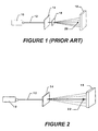
- An x-ray diffraction system operating in this manner is depicted in schematic form in FIG. 1. As shown, the system is arranged for transmission mode diffraction.
- An x-ray radiation source 10 directs a beam of x-rays 12 onto a specimen 14 to be examined. The x-rays are scattered from the specimen in a pattern indicative of its atomic structure. This scattered energy may thereafter be detected by a two-dimensional (2D) detector 18, which detects the transmission variation of the scattered signal in the plane perpendicular to the direction of the original beam.
- 2D detector 18 two-dimensional
- this system uses a beamstop 20 to block the direct x-ray beam that passes through the sample from reaching the detector. This prevents the detection of the diffracted energy from being disturbed by interaction of the high-energy transmitted x-ray beam with the detector.
- FIG. 1 A glassy-carbon (GC) filter 16, which has high-angle scattering that is featureless, is inserted in the path of the transmitted x-ray beam, and the resulting two-dimensional pattern is detected. From this, the desired information regarding the intensity of the transmitted beam may be determined.
- GC glassy-carbon
- a radiation diffraction measurement system that measures radiant energy diffracted from a sample.
- the system includes a radiant energy source from which a beam of radiant energy is directed.
- the radiant energy source is an x-ray source, but the invention may be equally applied to systems using other types of sources.
- a detector is also provided that detects the intensity of radiant energy incident upon different regions of it. This detected energy may include energy diffracted from the sample as well as energy received from the transmitted radiant energy beam. In particular, when the beam is directed at the sample being examined, some of the beam energy is diffracted, while some of is transmitted through the sample.
- the detector of the present invention detects both the diffracted energy and the transmitted beam energy, and does so simultaneously.
- the beam transmitted through the sample is preferably attenuated to reduce its intensity magnitude prior to its reaching the detector.
- This allows a beam to be used that has sufficiently high energy to provide good energy diffraction from the sample, while preventing the high energy of the transmitted beam from saturating the detector.
- the attenuator will block an outer portion of the transmitted beam from reaching the detector. In this way, the attenuator creates a local minimum intensity region on the detection surface that surrounds the region of the detector upon which the beam is incident. This local intensity region is an easily detectable boundary between a region of the detector upon which the beam is incident and one upon which the diffracted energy from the sample is incident. Thus, a single detection frame of the detector will simultaneously contain intensity information on both the beam and the diffracted radiation.
- the attenuator also provides a filtering mechanism that provides a broadband reduction in the per-unit-area intensity of the beam.
- the detector used with the system must be able to detect radiation intensity in different regions of the detection area. This allows detection of the beam intensity and detection of the diffracted energy to be done simultaneously.
- the detector is a multi-element detector, and has a plurality of detection "pixels" across a detection surface, each of which generates an individual intensity measurement.
- a single detection "frame” is generated.
- this frame is stored in a local data storage device. Thereafter, the regions of the detector upon which the transmitted beam and diffracted energy are incident, respectively, may be determined.
- a preferred method of determining the relative intensities of the transmitted beam and the diffracted beam energy involves first transmitting the beam through the attenuator toward the detector without the sample in place.
- This "air scatter" provides a baseline, and may be used to determine the center of the region on the detector upon which the transmitted beam is incident.
- the resulting detector intensity frame from the air scatter is stored.
- a sample is thereafter loaded into the system, and a scan is initiated by directing the initial beam at the sample with the detector in an active state.
- a single frame from the detector is stored, and may then be analyzed to determine the region of the detector upon which the transmitted beam is incident.
- intensity measurements from the frame are examined to locate local minimum intensity points surrounding the center.
- multiple radial directions from the center are examined until a local minimum is reached along each of the directions. These directions may be mutually orthogonal so as to determine the change in intensity in the frame in four primary directions from the center. The minimum intensity points closest to the center along these directions will lie in the shadow region created by the attenuator blocking the outer portion of the transmitted beam. From these points, interpolation may be used to determine a boundary surrounding the region of the detector upon which the transmitted beam is incident.
- the intensities measured within that region on the detector are integrated over the region itself to determine an average transmitted beam intensity.
- the measurements within the beam region from the air scatter may also used in the integration of the beam intensity along with those resulting from the transmitted beam during the sample measurement.
- the intensity values collected by the detector outside of the beam boundary during the sample measurement are then integrated over the area outside of the beam boundary to determine the average intensity of the diffracted radiation. Once the intensity calculations are made, a transmission coefficient may be calculated.
- FIG. 1 is a diagrammatic view of a radiant energy diffraction measurement system according to the prior art.
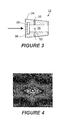
- FIG. 2 is a diagrammatic view of a radiant energy diffraction measurement system according to the present invention.
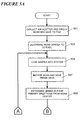
- FIG. 3 is a cross sectional view of a radiant energy beam attenuator according to the present invention.
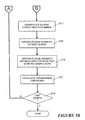
- FIG. 4 is a still image resulting from a measurement using the measurement device of the present invention.
- FIGS. 5A and 5B taken together, form a flowchart generally depicting a set of steps performed while using a measurement device according to the present invention.
- FIG. 2 Shown in FIG. 2 is an x-ray diffraction apparatus according to the present invention.
- An x-ray radiation source 10 directs an x-ray beam 12 at a sample 14 under test.
- the interaction of the x-ray beam with the molecular structure of the sample causes diffraction of the x-rays such that a diffraction pattern is produced.
- This diffraction pattern is detected by 2D detector 18, and the pattern indicates the nature of the interaction with the sample 14, and therefore provides information about its molecular structure.
- beamstop 22 is located in the path of the portion of the x-ray beam that is transmitted through the sample 14.
- beamstop 22 does not simply block the x-ray beam from reaching the detector. Instead, the beamstop 22 functions as an attenuator of the beam, allowing a center portion of it to reach the 2D detector 18. That is, an outer portion of the beam is completely blocked by the beamstop, but a center portion is allowed to pass through the beamstop, subject to a certain degree of additional attenuation.
- the term “beamstop” will therefore be used interchangeably with the term “attenuator” in describing element 22 of the figures.
- the beamstop 22 is shown in more detail in FIG. 3.
- FIG. 3 depicts a preferred embodiment of beamstop 22, with the arrow indicating the direction of the incident beam.
- housing 24 surrounds a center bore 26 through the beamstop.
- the bore 26 is preferably cylindrical, but may be other shapes as well, provided the shape is taken into account in the ultimate distribution of the energy transmitted through the beamstop.
- FIG. 3 is not necessarily to scale and the diameter of the bore 26 and the diameter of the beamstop 22 are determined by the desirable beam size, beam divergence, sample-to-detector distance and other configuration parameters.
- the actual beamstop diameter is larger than the primary beam spot on the detector.
- the beam spot on a detector positioned 600 mm from the sample may be 2.5 mm given a particular beam divergence.
- a beamstop according to the present invention that would be appropriate for this configuration is 4 mm in diameter and has a bore 26 with a diameter of 1 mm. In such a case, approximately 84% of the crossing area of the beam spot is blocked by the beamstop 22. Due to the uneven distribution of the beam intensity profile, the portion of the beam not directly blocked by the beamstop 22 normally has a higher intensity per unit area. This portion of the energy is passed, but is subject to attenuation in the process.
- Attenuation of the unblocked energy is provided by filter element 28, which resides in a front mounting region 30 of housing 24, which has a bore diameter greater than that of main bore 26.
- the filter element is preferably cylindrical, and may be constructed from any of a number of materials including copper, nickel, gold, aluminum, or any other homogenous material that will attenuate the beam without generating strong fluorescence. With such a material, the degree of attenuation may be controlled by controlling the thickness of the material.
- the filter causes a broadband reduction in the intensity of the transmitted beam.
- the degree of attenuation may be controlled by other system parameters as well, such as the diameter of bore 26 and the intensity of the initial x-ray beam.
- the bore 26 has a diameter of 1 mm
- the filter element 28 is made of nickel and has a thickness of 0.1 mm.
- the beamstop of FIG. 3 also includes mounting bores 32 in two perpendicular directions. These bores allow the attachment of wires to the beamstop to allow it to be precisely positioned.
- the wires are held tight in four directions to a linear adjustment mechanism so that the beamstop position can be adjusted.
- the linear adjustment may also be done through motion feedthroughs so the beamstop can be kept in a vacuum or other isolated environment.
- the transmitted beam is incident upon detector 18 (FIG. 2). In its attenuated form, it does not saturate the detector, and its intensity can be effectively quantified.
- detector 18 By blocking a portion of the beam that surrounds the center portion, a shadow region is produced at the detector that separates the detected transmitted beam from the detected scattered x-rays. This shadow region allows the detected transmitted beam to be accurately distinguished from the detected scattered x-ray pattern.
- the detected intensity of the transmitted x-ray beam can be determined, and used to normalize the detected signal of the scattered x-rays.
- FIG. 4 A still image of the signal detected by detector 18 during an experiment using the present invention is shown in FIG. 4. As shown, a bright spot is present at the center of the image, indicating the location at which the transmitted and attenuated x-ray beam was incident on the detector. Surrounding the bright spot is a ring of shadow, where the beamstop blocked any x-ray energy of the transmitted beam from reaching the detector. This shadow region separates the bright spot of the transmitted beam from the remainder of the diffracted x-ray energy, which forms the pattern that surrounds the shadow region of the image in FIG. 4.
- FIG. 5A shows a first portion of a processing procedure according to the present invention.
- step 501 an x-ray diffraction scan is initiated with no sample in place, that is, an "air" scattering is done.
- the signal levels detected by the detector array during the air scatter are stored as a single file.
- step 503 the approximate location of the center of the transmitted beam is also determined. Since the beamstop causes a shadow to be formed around the transmitted beam portion, the portion of the detector array upon which the beam is incident may be easily detected. In practice, the beam location is has been found to be detectable to within one-half pixel on the detector array.
- step 505 With the beam center having been located, a sample is then loaded into the system (step 505).
- step 507 an x-ray diffraction scan of the sample is performed, and the intensities detected by the detector are recorded in a detection file. From this detection file, analysis of the scan data may be performed.
- the extent of the transmitted beam region is determined.
- four primary directions from the beam center are selected, and a minimum detected intensity level is found along each direction (step 509). That is, four mutually orthogonal axes that radiate out from the previously determined beam center on the detector are selected, and the intensity values are examined along each of these axes until a minimum value is reached. Since the minima should fall within the shadow region surrounding the transmitted beam, the determined minima may be used as points that define the limits of the transmitted beam in four directions on the surface of the detector. The boundary defined by the shadow region is then interpolated from the four minimum intensity points and knowledge of the beam characteristics. For example, the beam shape in the system of Fig. 2 is elliptical, so an ellipse is interpolated from the detected minima. This ellipse is then used to define the region of the transmitted beam incidence on the detector (step 511).
- step 513 the scan intensity outside of the ellipse is integrated, giving the signal intensity of the scattered x-rays.
- the scan intensity within the ellipse is also integrated to determine the intensity of the transmitted beam (step 515).
- the integration of beam intensity in the preferred embodiment of the invention uses both the beam intensity measured during the scattering measurement of step 507 and the beam intensity measured during the test measurement of step 501. Alternatively, the integration may use just the beam measurement made during the scattering. Although some of the scattered x-rays may be scattered into the elliptical region defining the transmitted beam, the intensity of the transmitted beam is several orders of magnitude greater than that of the scattered x-rays, and the effect is therefore negligible.
- a transmission coefficient may be calculated, as shown in step 517.
- the transmission coefficient is the ratio of the test beam intensity from step 501 to the transmission intensity from step 515. Once this coefficient has been determined, it may be used to calculate the sample density or thickness at the particular sample position.
- Step 519 of FIG. 5B shows a return to step 505 to load another sample if desired. Since the initial air scattering serves as a calibration of the system, it is not necessary to perform this step again before beginning another scan. Once the last sample has been examined, the procedure is terminated. Preferably, the calibration steps are repeated for each new set of scattering measurements. It will be apparent to those skilled in the art that, although the steps of calculating intensities and the transmission coefficient are shown prior to the loading of a new sample, the measurements may also be stored and the calculations done later. The calculations may also take place while subsequent samples are being examined.
Landscapes
- Chemical & Material Sciences (AREA)
- Crystallography & Structural Chemistry (AREA)
- Physics & Mathematics (AREA)
- Health & Medical Sciences (AREA)
- Life Sciences & Earth Sciences (AREA)
- Analytical Chemistry (AREA)
- Biochemistry (AREA)
- General Health & Medical Sciences (AREA)
- General Physics & Mathematics (AREA)
- Immunology (AREA)
- Pathology (AREA)
- Analysing Materials By The Use Of Radiation (AREA)
Applications Claiming Priority (2)
| Application Number | Priority Date | Filing Date | Title |
|---|---|---|---|
| US239419 | 1999-01-28 | ||
| US09/239,419 US6163592A (en) | 1999-01-28 | 1999-01-28 | Beam scattering measurement system with transmitted beam energy detection |
Publications (3)
| Publication Number | Publication Date |
|---|---|
| EP1024356A2 true EP1024356A2 (de) | 2000-08-02 |
| EP1024356A3 EP1024356A3 (de) | 2002-12-18 |
| EP1024356B1 EP1024356B1 (de) | 2008-02-06 |
Family
ID=22902046
Family Applications (1)
| Application Number | Title | Priority Date | Filing Date |
|---|---|---|---|
| EP99124429A Expired - Lifetime EP1024356B1 (de) | 1999-01-28 | 1999-12-08 | Strahlstreuungsmessvorrichtung mit Nachweis der durchgehenden Strahlenenergie |
Country Status (3)
| Country | Link |
|---|---|
| US (1) | US6163592A (de) |
| EP (1) | EP1024356B1 (de) |
| DE (1) | DE69938096T2 (de) |
Cited By (1)
| Publication number | Priority date | Publication date | Assignee | Title |
|---|---|---|---|---|
| DE102019208834B3 (de) * | 2019-06-18 | 2020-10-01 | Bruker Axs Gmbh | Vorrichtung zum Justieren und Wechseln von Strahlfängern |
Families Citing this family (22)
| Publication number | Priority date | Publication date | Assignee | Title |
|---|---|---|---|---|
| AU2003222026A1 (en) * | 2002-03-21 | 2003-10-08 | Bruker Axs, Inc. | Transmission mode x-ray diffraction screening system |
| US6751288B1 (en) * | 2002-10-02 | 2004-06-15 | The United States Of America As Represented By The United States Department Of Energy | Small angle x-ray scattering detector |
| DE10317677A1 (de) * | 2003-04-17 | 2004-11-18 | Bruker Axs Gmbh | Primärstrahlfänger |
| US6956928B2 (en) * | 2003-05-05 | 2005-10-18 | Bruker Axs, Inc. | Vertical small angle x-ray scattering system |
| GB0312499D0 (en) * | 2003-05-31 | 2003-07-09 | Council Cent Lab Res Councils | Tomographic energy dispersive diffraction imaging system |
| GB0409572D0 (en) * | 2004-04-29 | 2004-06-02 | Univ Sheffield | High resolution imaging |
| EP1720006A1 (de) * | 2005-05-02 | 2006-11-08 | F. Hoffmann-La Roche Ag | Methode und Vorrichtung zur Röntgenbeugunsanalyse |
| US7796726B1 (en) * | 2006-02-14 | 2010-09-14 | University Of Maryland, Baltimore County | Instrument and method for X-ray diffraction, fluorescence, and crystal texture analysis without sample preparation |
| US9486839B2 (en) | 2011-01-07 | 2016-11-08 | Huron Valley Steel Corporation | Scrap metal sorting system |
| DE102012013530B3 (de) * | 2012-07-05 | 2013-08-29 | Helmholtz-Zentrum Berlin Für Materialien Und Energie Gmbh | Vorrichtung zur Messung resonanter inelastischer Röntgenstreuung einer Probe |
| AT513660B1 (de) * | 2012-11-30 | 2014-09-15 | Anton Paar Gmbh | Verfahren und Vorrichtung zur Untersuchung von Proben |
| US9606073B2 (en) * | 2014-06-22 | 2017-03-28 | Bruker Jv Israel Ltd. | X-ray scatterometry apparatus |
| JP6999268B2 (ja) | 2016-01-11 | 2022-01-18 | ブルカー テクノロジーズ リミテッド | X線スキャタロメトリーのための方法および装置 |
| CN106770398B (zh) * | 2016-11-30 | 2019-11-26 | 中国科学院上海应用物理研究所 | 一种同步辐射x射线对面探测器的快速准直方法及系统 |
| US10816487B2 (en) | 2018-04-12 | 2020-10-27 | Bruker Technologies Ltd. | Image contrast in X-ray topography imaging for defect inspection |
| JP2019191168A (ja) | 2018-04-23 | 2019-10-31 | ブルカー ジェイヴィ イスラエル リミテッドBruker Jv Israel Ltd. | 小角x線散乱測定用のx線源光学系 |
| CN118624653A (zh) | 2018-07-05 | 2024-09-10 | 布鲁克科技公司 | 小角度x射线散射测量 |
| CN114424054B (zh) * | 2019-06-24 | 2024-03-22 | Sms集团有限公司 | 用于确定多晶产品的材料特性的设备和方法 |
| GB2585673B (en) * | 2019-07-10 | 2022-05-04 | The Nottingham Trent Univ | A sample inspection system |
| US11781999B2 (en) | 2021-09-05 | 2023-10-10 | Bruker Technologies Ltd. | Spot-size control in reflection-based and scatterometry-based X-ray metrology systems |
| US12249059B2 (en) | 2022-03-31 | 2025-03-11 | Bruker Technologies Ltd. | Navigation accuracy using camera coupled with detector assembly |
| CN119510465A (zh) * | 2024-09-25 | 2025-02-25 | 中国科学院高能物理研究所 | 一种x射线散射衍射实验入射光斑实时监测的方法和装置 |
Family Cites Families (3)
| Publication number | Priority date | Publication date | Assignee | Title |
|---|---|---|---|---|
| US5491738A (en) * | 1993-03-15 | 1996-02-13 | The United States Of America As Represented By The Administrator Of The National Aeronautics And Space Administration | X-ray diffraction apparatus |
| US5589690A (en) * | 1995-03-21 | 1996-12-31 | National Institute Of Standards And Technology | Apparatus and method for monitoring casting process |
| US6005913A (en) * | 1996-04-01 | 1999-12-21 | Siemens Westinghouse Power Corporation | System and method for using X-ray diffraction to detect subsurface crystallographic structure |
-
1999
- 1999-01-28 US US09/239,419 patent/US6163592A/en not_active Expired - Lifetime
- 1999-12-08 EP EP99124429A patent/EP1024356B1/de not_active Expired - Lifetime
- 1999-12-08 DE DE69938096T patent/DE69938096T2/de not_active Expired - Lifetime
Non-Patent Citations (3)
| Title |
|---|
| "Katalog der Firma Plano GmbH, Wetzlar" 1996 XP002216964 http://www.harz-online.de:80/html/vip/pdf/ 001/167-deu.pdf, retrieved 16/10/2002 * |
| BRUMBERGER, H: "small angle x-ray scattering" 1967 , GORDON AND BREACH , NEW YORK XP002216962 * page 309; figures 14,A * * |
| HAMMERSLEY ANDY: "FIT2D REFERENCE MANUAL" 26 August 1998 (1998-08-26) , INTERNET HTTP://WWW.ESRF.FR/COMPUTING/SCIENTIFIC/FI T2D/FIT2D_REF/NODE195.HTML , GRENOBLE XP002216963 retrieved on 16/10/2002 * the whole document * * |
Cited By (2)
| Publication number | Priority date | Publication date | Assignee | Title |
|---|---|---|---|---|
| DE102019208834B3 (de) * | 2019-06-18 | 2020-10-01 | Bruker Axs Gmbh | Vorrichtung zum Justieren und Wechseln von Strahlfängern |
| US11307155B2 (en) | 2019-06-18 | 2022-04-19 | Bruker Axs Gmbh | Device for adjusting and exchanging beamstops |
Also Published As
| Publication number | Publication date |
|---|---|
| EP1024356A3 (de) | 2002-12-18 |
| US6163592A (en) | 2000-12-19 |
| DE69938096T2 (de) | 2009-01-29 |
| DE69938096D1 (de) | 2008-03-20 |
| EP1024356B1 (de) | 2008-02-06 |
Similar Documents
| Publication | Publication Date | Title |
|---|---|---|
| US6163592A (en) | Beam scattering measurement system with transmitted beam energy detection | |
| JP4688955B2 (ja) | 同時かつ近位の透過イメージングおよび後方散乱イメージングによるx線検査 | |
| US7453985B2 (en) | Control of X-ray beam spot size | |
| RU2253861C2 (ru) | Устройство и способ для обнаружения неразрешенных предметов | |
| US6442233B1 (en) | Coherent x-ray scatter inspection system with sidescatter and energy-resolved detection | |
| JP5054518B2 (ja) | 物質の平均原子番号及び質量を求めるための方法及びシステム | |
| US10386532B2 (en) | Radiation signal processing system | |
| EP3771904B1 (de) | Messung der kristallitgrössenverteilung in polykristallinen materialien mittels zweidimensionaler röntgenbeugung | |
| US7068753B2 (en) | Enhancement of X-ray reflectometry by measurement of diffuse reflections | |
| EP0898704A1 (de) | Inspektionsausrüstung mittels kleinwinkeltopographie zur bestimmung der internen struktur und zusammensetzung eines objekt | |
| EP0105618A2 (de) | Verfahren und Vorrichtung zur röntgenologischen Bilderzeugung mit Kompensation der Streustrahlung | |
| US9222900B2 (en) | X-ray diffraction method of mapping grain structures in a crystalline material sample, and an X-ray diffraction apparatus | |
| JP2001524011A (ja) | 組織分析装置 | |
| US20060083350A1 (en) | Analysis device with variably illuminated strip detector | |
| EP2775295B1 (de) | Röntgenstrahlbrechungsverfahren zum Abbilden von Kornstrukturen in einer kristallinen Materialprobe und Röntgenstrahlbrechungsvorrichtung | |
| US8385503B2 (en) | X-ray diffraction contrast tomography (DCT) system, and an x-ray diffraction contrast tomography (DCT) method | |
| US6704390B2 (en) | X-ray analysis apparatus provided with a multilayer mirror and an exit collimator | |
| GB2083969A (en) | Scatter radiation fluoroscopy apparatus | |
| GB2107560A (en) | A method for determining the orientation of a crystal | |
| WO2023056156A1 (en) | Methods and systems for the concurrent generation of multiple substantially similar x-ray beams | |
| JPH0627056A (ja) | 物質組成及び構造分析方法 | |
| KR102736270B1 (ko) | 컨테이너 위험화물 정밀검색용 후방산란 방사선 영상시스템 및 그의 제어 방법 | |
| US20090074132A1 (en) | Computer tomography apparatus and method of examining an object of interest with a computer tomography apparatus | |
| CN110779940B (zh) | 发散束二维x射线衍射 | |
| CZ32376U1 (cs) | Rentgenfluorescenční skenovací analyzátor |
Legal Events
| Date | Code | Title | Description |
|---|---|---|---|
| PUAI | Public reference made under article 153(3) epc to a published international application that has entered the european phase |
Free format text: ORIGINAL CODE: 0009012 |
|
| AK | Designated contracting states |
Kind code of ref document: A2 Designated state(s): AT BE CH CY DE DK ES FI FR GB GR IE IT LI LU MC NL PT SE |
|
| AX | Request for extension of the european patent |
Free format text: AL;LT;LV;MK;RO;SI |
|
| PUAL | Search report despatched |
Free format text: ORIGINAL CODE: 0009013 |
|
| AK | Designated contracting states |
Kind code of ref document: A3 Designated state(s): AT BE CH CY DE DK ES FI FR GB GR IE IT LI LU MC NL PT SE |
|
| AX | Request for extension of the european patent |
Free format text: AL;LT;LV;MK;RO;SI |
|
| 17P | Request for examination filed |
Effective date: 20030215 |
|
| AKX | Designation fees paid |
Designated state(s): DE GB NL |
|
| GRAP | Despatch of communication of intention to grant a patent |
Free format text: ORIGINAL CODE: EPIDOSNIGR1 |
|
| GRAS | Grant fee paid |
Free format text: ORIGINAL CODE: EPIDOSNIGR3 |
|
| GRAA | (expected) grant |
Free format text: ORIGINAL CODE: 0009210 |
|
| AK | Designated contracting states |
Kind code of ref document: B1 Designated state(s): DE GB NL |
|
| REG | Reference to a national code |
Ref country code: GB Ref legal event code: FG4D |
|
| REF | Corresponds to: |
Ref document number: 69938096 Country of ref document: DE Date of ref document: 20080320 Kind code of ref document: P |
|
| PLBE | No opposition filed within time limit |
Free format text: ORIGINAL CODE: 0009261 |
|
| STAA | Information on the status of an ep patent application or granted ep patent |
Free format text: STATUS: NO OPPOSITION FILED WITHIN TIME LIMIT |
|
| 26N | No opposition filed |
Effective date: 20081107 |
|
| PGFP | Annual fee paid to national office [announced via postgrant information from national office to epo] |
Ref country code: GB Payment date: 20151221 Year of fee payment: 17 |
|
| PGFP | Annual fee paid to national office [announced via postgrant information from national office to epo] |
Ref country code: NL Payment date: 20151221 Year of fee payment: 17 |
|
| PGFP | Annual fee paid to national office [announced via postgrant information from national office to epo] |
Ref country code: DE Payment date: 20151224 Year of fee payment: 17 |
|
| REG | Reference to a national code |
Ref country code: DE Ref legal event code: R119 Ref document number: 69938096 Country of ref document: DE |
|
| REG | Reference to a national code |
Ref country code: NL Ref legal event code: MM Effective date: 20170101 |
|
| GBPC | Gb: european patent ceased through non-payment of renewal fee |
Effective date: 20161208 |
|
| PG25 | Lapsed in a contracting state [announced via postgrant information from national office to epo] |
Ref country code: NL Free format text: LAPSE BECAUSE OF NON-PAYMENT OF DUE FEES Effective date: 20170101 |
|
| PG25 | Lapsed in a contracting state [announced via postgrant information from national office to epo] |
Ref country code: DE Free format text: LAPSE BECAUSE OF NON-PAYMENT OF DUE FEES Effective date: 20170701 Ref country code: GB Free format text: LAPSE BECAUSE OF NON-PAYMENT OF DUE FEES Effective date: 20161208 |