EP1023965B1 - Starkstromversorgung zum Schweissen - Google Patents
Starkstromversorgung zum Schweissen Download PDFInfo
- Publication number
- EP1023965B1 EP1023965B1 EP00100986A EP00100986A EP1023965B1 EP 1023965 B1 EP1023965 B1 EP 1023965B1 EP 00100986 A EP00100986 A EP 00100986A EP 00100986 A EP00100986 A EP 00100986A EP 1023965 B1 EP1023965 B1 EP 1023965B1
- Authority
- EP
- European Patent Office
- Prior art keywords
- current
- inverter
- power supply
- welding
- pulses
- Prior art date
- Legal status (The legal status is an assumption and is not a legal conclusion. Google has not performed a legal analysis and makes no representation as to the accuracy of the status listed.)
- Revoked
Links
Images


Classifications
-
- B—PERFORMING OPERATIONS; TRANSPORTING
- B23—MACHINE TOOLS; METAL-WORKING NOT OTHERWISE PROVIDED FOR
- B23K—SOLDERING OR UNSOLDERING; WELDING; CLADDING OR PLATING BY SOLDERING OR WELDING; CUTTING BY APPLYING HEAT LOCALLY, e.g. FLAME CUTTING; WORKING BY LASER BEAM
- B23K9/00—Arc welding or cutting
- B23K9/10—Other electric circuits therefor; Protective circuits; Remote controls
- B23K9/1006—Power supply
- B23K9/1043—Power supply characterised by the electric circuit
- B23K9/1056—Power supply characterised by the electric circuit by using digital means
- B23K9/1062—Power supply characterised by the electric circuit by using digital means with computing means
-
- H—ELECTRICITY
- H04—ELECTRIC COMMUNICATION TECHNIQUE
- H04M—TELEPHONIC COMMUNICATION
- H04M3/00—Automatic or semi-automatic exchanges
- H04M3/42—Systems providing special services or facilities to subscribers
- H04M3/4228—Systems providing special services or facilities to subscribers in networks
- H04M3/42289—Systems providing special services or facilities to subscribers in networks with carrierprovider selection by subscriber
-
- B—PERFORMING OPERATIONS; TRANSPORTING
- B23—MACHINE TOOLS; METAL-WORKING NOT OTHERWISE PROVIDED FOR
- B23K—SOLDERING OR UNSOLDERING; WELDING; CLADDING OR PLATING BY SOLDERING OR WELDING; CUTTING BY APPLYING HEAT LOCALLY, e.g. FLAME CUTTING; WORKING BY LASER BEAM
- B23K9/00—Arc welding or cutting
- B23K9/09—Arrangements or circuits for arc welding with pulsed current or voltage
- B23K9/091—Arrangements or circuits for arc welding with pulsed current or voltage characterised by the circuits
-
- B—PERFORMING OPERATIONS; TRANSPORTING
- B23—MACHINE TOOLS; METAL-WORKING NOT OTHERWISE PROVIDED FOR
- B23K—SOLDERING OR UNSOLDERING; WELDING; CLADDING OR PLATING BY SOLDERING OR WELDING; CUTTING BY APPLYING HEAT LOCALLY, e.g. FLAME CUTTING; WORKING BY LASER BEAM
- B23K9/00—Arc welding or cutting
- B23K9/10—Other electric circuits therefor; Protective circuits; Remote controls
- B23K9/1006—Power supply
- B23K9/1043—Power supply characterised by the electric circuit
-
- H—ELECTRICITY
- H04—ELECTRIC COMMUNICATION TECHNIQUE
- H04M—TELEPHONIC COMMUNICATION
- H04M7/00—Arrangements for interconnection between switching centres
- H04M7/006—Networks other than PSTN/ISDN providing telephone service, e.g. Voice over Internet Protocol (VoIP), including next generation networks with a packet-switched transport layer
- H04M7/0066—Details of access arrangements to the networks
-
- H—ELECTRICITY
- H04—ELECTRIC COMMUNICATION TECHNIQUE
- H04M—TELEPHONIC COMMUNICATION
- H04M7/00—Arrangements for interconnection between switching centres
- H04M7/12—Arrangements for interconnection between switching centres for working between exchanges having different types of switching equipment, e.g. power-driven and step by step or decimal and non-decimal
- H04M7/1205—Arrangements for interconnection between switching centres for working between exchanges having different types of switching equipment, e.g. power-driven and step by step or decimal and non-decimal where the types of switching equipement comprises PSTN/ISDN equipment and switching equipment of networks other than PSTN/ISDN, e.g. Internet Protocol networks
Definitions
- the present invention relates to electric arc welding and more particularly to an improved welding power supply for creating a high welding current in a succession of current pulses according to the preambles of, respectively, claims 1 and 29. Further, the present invention relates also to a method of creating welding current in a succession of current pulses according to the preambles of, respectively, claims 19 and 27 (see, for example, US-A-4 947 021).
- the present invention utilizes an inverter of the transistor switching type for converting a three phase input power source to a load coupling transformer from which the AC output of the inverter can be rectified to create current flow between the electrode and workpiece of a welding operation.
- Such inverters employ a pulse width modulator operated at over 18 kHz for controlling the magnitude of the welding current flowing through the welding operation.
- These inverters are well known in the art and are generally shown in Blankenship 5,349,157 and Blankenship 5,351,175.
- These patents are background information illustrating a three phase inverter with current controlled by a high frequency pulse width modulator directing current pulses to the output transformer of the inverter.
- These patents illustrate the concept of a three phase inverter using a pulse width modulator with an error amplifier for controlling the current at the output of the inverter, which current is used in a welding operation.
- an output coupling transformer for the output stage of a transistor switching network type inverter with a secondary winding on the output transformer to create a generally positive terminal and a generally negative terminal.
- a positive current pulse can be directed through the welding operation followed by a negative current pulse.
- the positive current pulse is created by closing a first switch coupling the positive terminal at the output of the inverter through the electrode and workpiece to the negative or grounded terminal.
- the welding operation is connected to the negative terminal at the output of the inverter by a second transistor based switch.
- Each transistor based switch is in series with the electrode and workpiece together with a portion of a current sustaining inductor.
- an AC welding process is created.
- This process includes a succession of positive and negative current pulses.
- This architecture for creating an AC welding process has proven quite successful; however, when the welding current is high, i.e. over about 200 amperes, the snubbers in parallel with the first and second transistor based switches are very expensive and quite large. These snubbers had to maintain a high voltage across the switches when one pulse was turned off and the next pulse was turned on.
- U.S. Pat. No. 4,947,021 discloses a method and apparatus for TIG welding by passing an alternating current between a non-consumable lectrode and a workpiece to form an arc. This allows for creating a short cycle for cleaning the workpiece preparatory to the next heating cycle.
- U.S. Pat. No. 4,877,941 discloses a power supply systemfor consumable arc welding alternately switches between the reverse polarity and the straight polarity. The formation of an arc is detected. A polarity change control signal is generated when the arc duration reaches a predetermined time or when the quantity of charge reaches a predetermined value. The predetermined value of the welding current or voltage is reduced either immediately before or after the change in polarity.
- the snubber circuits necessary for handling these high voltages all involve either high losses and/or high cost.
- This high voltage is the inductance of the welding circuit multiplied by the change in instantaneous current per unit time during the switching operation. Since the transistors used in the welding operation at the output of the inverter have a fixed time needed for turning the switch off to stop conduction, the induced voltage to be handled by the snubber is proportional to the magnitude of the current at the time the switch begins to turn off and transitions between on and off. For that reason, in the past, circuits used in high current switching applications, such as electric arc welders, normally included elaborate snubber designs as discussed above to suppress the high voltage spikes occurring when the switch is turned off.
- the transient voltages when switching high currents at the output of the inverter stage are drastically reduced by the present invention in an AC welder of the type driven by a pulse width modulator operated switching inverter, especially one driven by a three phase power source.
- the invention has been tested on a 1200 ampere, AC inverter based power supply wherein the output current was reduced to 150 amperes before the switch was turned off at the trailing edge of each current pulse to reverse the polarity of the welding current.
- the other switch is turned on to create the opposite polarity current pulse, which current immediately shifts to 150 amperes in the opposite polarity and then quickly to the maximum current through the inductor in the welding circuit in the opposite direction.
- a welding power supply for creating a welding current in a succession of current pulses according to claims 1 and 29. Further, thus is provided a method of creating welding current in a succession of current pulses according to claims 19 and 27.
- the inverter stage that creates the current for use in an AC arc welder is turned off allowing the current to decay toward zero current when there is to be a polarity reversal.
- the switches are reversed terminating the existing current pulse and immediately creating the next current pulse of opposite polarity.
- the switches are in a power switching network including two transistor based switches, each having a conduction condition passing current from one of the terminals upon creation of the first logic signal and a non-conduction condition blocking current flow upon creation of a second logic signal.
- the invention can be used with a single output power switch that produces only pulses of a single polarity.
- the invention involves turning off the inverter stage, allowing the current pulse to decay to a selected current level and then switching off the output power switch to terminate the current pulse.
- the preferred embodiment of the invention is used for AC arc welding.
- Each of the current pulses has a trailing edge which trailing edge is created by turning off the inverter for a short time necessary to reduce the current of the pulse. Then the current pulse is terminated by applying the second logic signal to the switch thereby shifting the switch into the non-conduction condition.
- the first logic signal for each power switch whether a single switch DC unit or a two switch AC unit, is a logic 1 to turn the switch on.
- a logic 0 is the second logic signal to turn the switch, or switches, off.
- a sensor is used to measure the instantaneous value of the welding current
- a comparator is used to produce a low current signal when the instantaneous current is at a selected value substantially below the maximum current level of the current pulses and a circuit or program creates the second logic signal for turning a switch off upon production of the low current signal after generation of the signal to turn off the inverter stage.
- a circuit or program creates the second logic signal for turning a switch off upon production of the low current signal after generation of the signal to turn off the inverter stage.
- the inverter stage is first turned off and then the switches cause polarity reversal. After the current decays to the selected value in response to the inverter being turned off, the actual switching between the two polarities is effected. Since the induced voltage across the switches is a function of current at switching multiplied by the fixed inductance, the drastic reduction in the change in current during the switch reversing operation in turn drastically reduces the induced voltage. It has been found that 1000-1200 amperes can be switched with little or no snubber. This is an improvement in an AC welder of the type using a high frequency inverter switching network and output switches for creating opposite polarity current pulses.
- the inverter stage of the invention is powered by either a single or multiple phase input. Since the invention can be used with a three phase input, the welding operation is easily balanced, whereas prior switching units of this type used for high current welding were single phase power supplies with the resultant unbalanced power. Such unbalance is more of a problem at the high current levels used in the present invention.
- the inverter stage involves a switching network controlled by a pulse width modulator operated at a frequency above about 18 kHz.
- This pulse width modulator operates the switches in the inverter stage at a high rate.
- the average welding current of the AC welder is conveyed to an error amplifier for controlling the average current of the welding operation by changing the duty cycle of the pulse modulator in accordance with standard inverter practice.
- the current pulses created at the output of the power supply using the present invention is relatively low, i.e. less than about 400 Hz. Indeed, the AC welding operation is practiced in the general range of 40 Hz-200 Hz which is contrasted with the high frequency operation of the inverter stage.
- improved power supply can be used to create a single polarity pulse or, alternating polarity pulse.
- the welder has a DC negative mode, a DC positive mode or an AC mode.
- the inverter stage is turned off, allowing a decay in the maximum current to a lower, selected current value at which time the current pulse is terminated by opening the switch creating the current pulse.
- a voltage controlled oscillator or similar software programming is used to change the welding pulse frequency; but, the same frequency is used for the pulse width modulator operating the inverter stage.
- the AC welding frequency is easily adjusted by merely changing the rate of the oscillator, other circuits or program controlling the polarity switching network.
- the present invention can reduce the pulse current at termination of the current pulse to a level less than about 200 amperes and, preferably, to a level in the general range of 100-150 amperes.
- This low current switching to terminate the trailing edge of the current pulse can be used even when the maximum current of the pulse is 1000-1200 amperes.
- tremendously large, expensive snubbers were required in such high current AC power supplies.
- the opposite polarity current pulses are created by switching between first and second command signals.
- One command signal turns one switch on while the other command signal turns the other switch off. This reverses the polarity of the current pulses.
- a time delay circuit is employed for turning the inverter stage off before the command signals are switched to reverse the polarity of the output welding operation.
- first and second logic signals are related to a single switch.
- a logic 1 (first logic signal) turns the switch on and a logic 0 (a second logic signal) turns the switch off.
- first and second command signals are the signals for turning one switch on and the other switch off.
- These command signals are never the same logic and in accordance with the preferred embodiment of the present invention are created by the Q and Q terminals of the flip-flop.
- the logic signals relate to a single switch when a logic 1 turns the switch on and a logic 1 turns the switch off.
- each command signal has two logic signals indicative of the conductive state of the individual switches controlled by the command signals. When a command signal is called for, this generally means the switch turns on a logic signal.
- the primary object of the present invention is the provision of a welding power supply that creates a succession of current pulses having high current levels about 200 amperes and terminates the pulse by turning off a power switch, which power supply is modified whereby the turning off of the power switch occurs at a low current level, substantially below the maximum current of the pulse being terminated.
- Another object of the present invention is the provision of a unique AC power supply for electric arc welding, as defined above, which power supply has alternating current pulses with high maximum currents. The pulses are reversed by opening one power switch and closing another power switch when the power switch being opened is carrying a current drastically below the high current of the power supply.
- Still a further object of the present invention is the provision of a power supply, as defined above, which power supply is driven by an inverter stage, that is connected to a three phase power source and operated at a high frequency by a pulse width modulator whereby the high frequency inverter stage provides current for a low frequency AC welding operation.
- Still a further object of the present invention is the provision of an improved welding power supply for creating a succession of current pulses as defined above, which power supply utilizes transistor based switches, such as IGBTs, which power supply requires little or no snubbing when the polarity reversing switches are turned off.
- Yet another object of the present invention is the provision of an AC welding power supply for creating a succession of current pulses, as defined above, which power supply can operate an output frequency as low as 40-60 Hz driven by an inverter stage operated at higher than about 20 kHz and at maximum currents in excess of about 200 amperes.
- This is a unique AC power supply for electric arc welding that incorporates the advantages of high frequency inverter conversion with the capability of a low frequency output current at high output current levels.
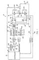
- FIGURES 1 and 1A show an AC welding supply 10 for passing an alternating current through electrode E and grounded workpiece W.
- Power supply 10 utilizes a standard inverter stage 12 having a rectifier input 14 and adapted to provide DC current at high levels to output switching network 16, which output network creates the current pulses of power supply 10 for performing a welding operation at workpiece W.
- a full wave rectifier 18 is connected to the inverter stage so the multi-phase input voltage to rectifier 14 is converted to a DC current source having a high maximum current level exceeding 200 amperes and preferably as high as 1000-1200 amperes.
- Inverter stage 12 is somewhat standard in architecture and includes an AC input 20 shown as a multi-phase power supply forming an input to rectifier 14 that directs a DC link 22 to the transistor switching network 30 for providing alternating current pulses through primary winding 34 of load transformer 32.
- a secondary winding 36 that has a center null point 38 is grounded and connected to workpiece W of the welding operation.
- the transistor switching network includes MOSFET switches or other similar transistor type switches for creating alternating current pulses in primary winding 34.
- Output transformer 32 has a very low inductance so the network 30 can be turned off quite rapidly.
- switching network 30 is operated by a somewhat standard pulse width modulator 40 operated at over 18 kHz and preferably between 20-40 kHz as shown in the prior Stava patent.
- the pulse width modulator control of a transistor switching network forming a converter or inverter is standard technology and the output current of the inverter stage is controlled by the voltage on line 42 from error amplifier 50, which amplifier may be software implemented in response to the voltage level on input line 52 having a voltage or digital word representative of the desired output current of power supply 10.
- the desired current level is set to a value exceeding about 200 amperes.
- the representative signal on input line 52 is compared by amplifier 50 with an average output current of the power supply in the form of the voltage signal or digital word on input line 54.
- the voltage from current measuring shunt 60 has a value representative of the instantaneous current value in line 62.
- a current averaging circuit 64 averages the instantaneous current value in line 62, which may be an analog or digital value. Circuit 64 creates an average current representative voltage signal or word in input line 54 of amplifier 50. As so far described, the inverter stage involves standard technology.
- controller 70 which may be software in a computer, or analog circuit, creates the representative voltage on line 52 in accordance with standard control concepts; however, in addition to the voltage or word in line 52, controller 70 also provides an inverter off signal in line 72.
- a logic 1 in line 72 immediately deactivates the pulse width modulator to turn inverter state 12 off so that it no longer supplies current to rectifier 18.
- Controller 70 also creates switch command signals in lines 80, 82 wherein a first logic, i.e. logic 1, immediately turns the corresponding output power switch on and a second logic, i.e. logic 0, which immediately turns the corresponding output power switch off.
- Full wave rectifier 18 includes diodes D1-D4 to create a positive current terminal 90, a negative current terminal 92 and a ground or common terminal 94 connected to center tap or null point 38 and to workpiece W.
- Power supply 10 utilizes output switching network 16 for creating high current pulses between electrode E and workpiece W. As illustrated, a first transistor based switch SW1, in the form of an IGBT, is closed upon receiving a command signal in line 80.
- switch SW1 Closing of switch SW1 creates a current pulse from positive terminal 90 through the positive segment 112 of output inductor 110 and then across the arc of the welding process.
- a second transistor based switch SW2 in the form of an IGBT, is closed upon receiving a logic 1 in line 82 for creating a negative current pulse through negative segment 114 of inductor 110 and to the negative terminal 52 of rectifier 18 forming the output of the inverter stage 12.
- Snubbers 100, 102 are connected in parallel across switches SW1, SW2, respectively. Without implementing the basic aspect of the present invention, these snubbers must be quite large and must handle a tremendously high voltage, since the induced voltage equals the value of the inductor segment 112 or 114 and the differential or instantaneous change in current.
- network 30 of inverter stage 12 is turned off by a signal in line 72 immediately before the logic or command signals in lines 80, 82 are reversed.
- the current supply is turned off before the conductive conditions of switches SW1, SW2 are reversed.
- Many structures could be used to accomplish this control operation. Such structures could be hardwired, software or combinations thereof.
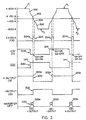
- a hardwired control circuit or device 150 includes the logic network shown in FIGURE 2. The output pulses from the control device or logic network are shown in the time coordinated graphs of FIGURE 3 taken together with the resulting alternating current pulses P 1 , P 2 of the current graph at the top of FIGURE 3.
- the logic network includes flip-flop 160 having its Q terminal connected to line 80 and its Q terminal connected to line 82.
- This flip-flop can be software or replayed by another non-coincident device.
- the logic on these terminals is shown in graphs 200, 202 in FIGURE 3.
- Data terminal D of flip-flop 160 is connected to output line 172 of oscillator 170 which can be software implemented.
- the binary logic on data terminal D of flip-flop 160 is shown in graph 206 constituting the output of oscillator 170 appearing in line 172.
- a clocking pulse must be received at clock terminal CK illustrated as being connected to the output 182 of a voltage level comparator 180.
- These logic devices are illustrated in analog terms and symbols; however, digital circuits are used also.
- Flip-flop 160 operates in accordance with standard practice providing the logic shown on graphs 200, 202 at the output of the flip-flop 160 and on lines 80, 82. The logic on these lines controls switches SW1, SW2, respectively.
- a clock pulse 204a appears when the data D shown in graph 206 is a logic 0.
- This clocking action causes a logic 0 to appear on command signal line 80 and a logic 1 on command signal line 82, as shown in graphs 200, 202.
- point 200a there is a reversal in the conductive states of switches SW1, SW2.
- the command signals on lines 80, 82 are again reversed at point 200b upon receipt of clocking pulse 204b when graph 206 is at a logic 1.
- the polarity of the current pulses is again reversed from the negative polarity pulse P 2 to the positive polarity pulse P 1 .
- Oscillator 170 that creates the signal shown as graph 206 in FIGURE 3 is a standard voltage controlled oscillator wherein the voltage input on line 174 changes the frequency of the pulse in output 172. This change in the oscillator rate changes the reversal frequency for the polarity of the pulses shown in the upper graph of FIGURE 3.
- the duty cycle of oscillator 170 can be changed. The duty cycle is shown in FIGURE 3 as 50%.
- Clocking pulses in line 182 as shown by graph 204 in FIGURE 3 are created by comparing the voltages on input lines 184, 186.
- Input line 184 is the instantaneous arc current in the welding operation as sensed by shunt 60.
- the voltage on input 186 is the output of rheostat 188 which is set to correspond with a voltage on line 184 which is at a selected value preferably in the range of 100-150 amperes and generally less than about 200 amperes.
- a logic 1 appears in line 182 when the instantaneous current is below the selected value set by rheostat 188, illustrated as 100 amperes.
- pulses 204a-204c represent the time during which comparator 180 outputs a logic 1 indicating a current less than the selected value at the input 186.
- NAND gate 230 has an input 232 with a logic on line 82 which is shown in graph 202 of FIGURE 3.
- the other input to gate 230 is line 172 which is graph 206 in FIGURE 3.
- NAND gate 240 has an input 242 connected to line 80 and shown as graph 200 in FIGURE 3.
- the oscillator inverted logic on line 172a is shown in graph-202 of FIGURE 3.
- the logic in line 72 is the inverter off signal shown in graph 222 of FIGURE 3. This inverter off signal occurs as soon as the oscillator graph 206 changes logic.
- Inverter 212 is used in logic network 210 for accomplishing the proper creation of signals turning inverter stage 12 off. As shown in FIGURE 3, the off signals 222a-222c occur immediately before clock pulses 204a-204c cause switches SW1 and SW2 to reverse. Thus, the inverter is turned off and held off during pulses 222a-222c. The logic on the output of flip-flop 160 can not change until the next clock pulse occurs.
- the current as shown in the upper graph decays along line 300 until the reversal point 200a is reached at point 302 of the graph. Thereafter, there is an immediate reversal of polarity by changing the logic on lines 80, 82 as shown in graphs 200, 202. This requires a certain transition time inherent in the IGBTs as indicated to occur between point 302 and point 304. Inverter stage 12 is again turned on and the current is increased along line 306 to the maximum level. This same operation occurs during each reversal of the polarity of current pulses P 1 , P 2 as shown in FIGURE 3. There is a very short delay between points 302 and 304 caused by the inherent switching time of switches SW1, SW2. These switches are transistor base which indicates they are not commutated.
- the present invention is schematically illustrated in the AC current shown in FIGURE 4 as alternating pulses P 3 , P 4 .
- an inverter off signal occurs at point 320 in pulse P 3 .
- the current decays through the output inductor along line 322 until it reaches a low level determined by the selected low current value illustrated as 100 amperes. This current is substantially below the maximum current of 1200 amperes for pulse P 3 .
- switches SW1 and SW2 are reversed according to the logic on lines 80, 82.
- pulse P 4 is immediately created as indicated along generally vertical line 330 which is a theoretical condition to point 332 at which the current is driven to the negative maximum level.
- the invention can be used with a standard series inductor in the positive or negative output circuit with the result that the current would not shift between the selected values as rapidly.
- the AC current shown in FIGURE 4 is representative in nature and illustrates the basic concept of the invention which involves turning off the inverter stage, waiting until the current decays to a selected value and then reversing the switches to reverse the polarity of the high current pulses.
- the frequency and duty cycle of the output pulses can be varied by changing the software schematically illustrated as oscillator 170 in FIGURE 2.
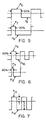
- FIGURES 5 and 6 This feature is schematically illustrated in FIGURES 5 and 6.
- the duty cycle between pulses P 5 and P 6 is 50%.
- the duty cycle between pulses P 7 and pulse P 8 is 20% while maintaining the same frequency.
- the frequency is increased so that a 50% duty cycle between pulse P 9 and pulse P 10 produces a smaller individual pulse due to the increased frequency.
- This increased frequency can have a change in the duty cycle as illustrated wherein pulse P 11 has a 20% duty cycle with respect to pulse P 12 .
- the term "duty cycle" is used herein to indicate the relative time between the positive pulse and the negative pulse. This unbalanced condition can be advantageous in certain welding operations where conduction in one direction is substantially different than conduction in the opposite direction.
- amplitude a for pulse P 13 is substantially less than the amplitude b for pulse P 14 .
- This concept allows higher current in one direction than another.
- the pulses P 5 -P 14 utilize the present invention wherein the termination of the pulse is effected by first turning off the inverter stage and then reversing the switches SW1, SW2. Other changes in the relative shapes of the alternating pulses can be implemented.
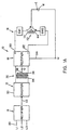
- FIGURES 8 and 9 A further modification of the preferred embodiment is illustrated in FIGURES 8 and 9 wherein a welding power supply 400 produces a series of single polarity pulses P 20 as shown in FIGURE 9.
- a welding power supply 400 produces a series of single polarity pulses P 20 as shown in FIGURE 9.
- a single switch SW3 is employed for directing the pulse through the arc between electrode E and grounded workpiece W.
- the basic concept of turning off the inverter allowing high current to decay to a low selected value and then turning off the power switch, such as an IGBT, is clearly illustrated.
- the novel, inventive concept is turning off the high current pulse and then turning off the power switch in a welding power supply of the type driven by a high frequency inverter.
- the inverter 402 has an output controlled by a single switch SW3 for passing current pulse P 20 through inductor 404 and across electrode E and grounded workpiece W.
- a command signal in line 410 has a logic 1 when switch SW3 is on and a logic 0 when the switch is off.
- the logic on line 410 is controlled by logic network 412 having an input 414 for turning the switch on and a logic in line 416 for turning the switch off.
- Control network which may be software, is illustrated as a hardwired oscillator 420 having an output 422 for turning inverter 402 on or off as indicated by the logic in line 424. If switch SW3 were on all the time, a square wave current pulse would appear at electrode E.
- switch SW3 When the inverter is turned on, switch SW3 is turned on by the logic on line 414. However, when the inverter is turned off, switch SW3 is not immediately turned off. To turn switch SW3 off requires a logic signal in line 416.
- This logic signal is the output of AND gate 430 having an inverter 432 for inverting the logic from oscillator 420. This inverted logic appears on line 432a at the input of gate 430.
- the other input to gate 430 is the output 440a of comparator 440 having a first voltage input in line 442 from current sensor 440 controlled by the instantaneous welding current as measured by shunt 446.
- the second input to comparator 440 is the voltage on line 450 having a voltage or word representative of a selected current value, such as 100 amperes.
- a logic 1 appears in line 432a.
- a logic 1 appears in the second input 440a of gate 430. This causes a logic 1 to appear in line 416 to open switch SW3 and terminate the current pulse.
- the oscillator is turned on switch SW3 is turned on. This is shown in FIGURE 9 at the leading edge of pulse P 20 .
- the invention involves turning off inverter 402, as indicated at point 460.
- the current through switch SW3 decays along line 462.
- gate 430 When the decaying instantaneous arc current reaches a selected value, indicated to be 100 amperes, gate 430 produces a logic 1 to turn switch SW3 off.
- This modification of the invention is presented to show the primary aspect of the present invention in the context of a single pulse power supply.
- the pulses P 20 occur at a frequency determined by the frequency of oscillator 420 and have a duty cycle of this oscillator, which oscillator is operated in accordance with the discussion of oscillator 170 in FIGURE 2.
- a single series of pulses can be created using the present invention, or an alternating welding current can be created.
Claims (37)
- Schweißleistungsversorgung (10) zum Erzeugen eines Schweißstroms in einer Folge von Strompulsen mit einem maximalen Stromniveau und einem Abschalt/Abkling-Zustand durch einen Inverter, bei der die Strompulse durch eine einen Induktor (110), einen Ausgangsleistungsschalter und eine in Schweißverbindung mit einem Werkstück (W) stehenden Elektrode (E) beinhaltende Serienschaltung laufen, wobei die Leistungsversorgung (10) aufweist (i) den Inverter mit einem an die Leistungsquelle zu verbindenden Eingang und wobei der Inverter zumindest einen ersten Ausgangsanschluß (90) bei einer ersten elektrischen Polarität beinhaltet, wenn der Inverter an ist, (ii) eine Steuerungsvorrichtung (70) zum Generieren eines Aus-Signals zum Ausschalten des Inverters und zum Entfernen von Strom von dem zumindest ersten Anschluss (90), um den Strompuls in Richtung eines Aus-Zustands zu wechseln; und (iii) den Ausgangsleistungsschalter, der einen ersten transistor-basierten Schalter mit einem Leitungszustand beinhaltet, der Strom von dem zumindest ersten Anschluss (90) beim Erzeugen eines ersten Steuersignals durchlässt, und mit einem Nichtleitungszustand, der Strom beim Erzeugen eines zweiten Steuersignals blockt, dadurch gekennzeichnet, dass die Steuerungsvorrichtung (70) weiterhin eine Schaltung oder ein Programm zum Erzeugen zumindest des zweiten Steuersignals beinhaltet und weiterhin Verzögerungsmittel zum Ausschalten des Inverters beinhaltet, bevor das zweite Steuersignal den Ausgangsleistungsschalter von dem Leitungszustand in den Nichtleitungszustand schaltet, wobei der Inverter einen zweiten Ausgangsanschluss (92) bei einer zweiten elektrischen Polarität beinhaltet, wenn der Inverter an ist, und die Schweißleistungsversorgung (10) weißt weiterhin einen Sensor zum Messen des Momentanwertes des Schweißstroms, einen Komparator zum Erzeugen eines schwachen Stromsignals auf, wenn der Momentanstrom bei einem ausgewählten Wert deutlich unterhalb des maximalen Stromniveaus ist, wobei die Schaltung oder das Programm zumindest das zweite Steuersignal beim Erzeugen eines schwachen Stromsignals nach einem Generieren eines Aus-Signals erzeugt, wobei der transistor-basierte Schalter von dem Leitungszustand in den Nichtleitungszustand geschaltet wird, wenn der Schweißstrom bei einem ausgewählten Wert ist.
- Schweißteistungsversorgung (10) wie in Anspruch 1 definiert zum Erzeugen einer Folge von positiven und negativen Strompulsen durch den Inverter, bei der die positiven Strompulse durch ein erstes Induktorsegment und eine mit einem Werkstück (W) in Serie geschalteten Elektrode (E) mittels Schließen des ersten transistor-basierten Schalters nach Empfang eines Steuersignals laufen und die negativen Strompulse durch ein zweites Induktorsegment und die Elektrode (E) mittels Schließen eines zweiten transistor-basierten Schalters nach Empfang eines Kommandosignals laufen, wobei die Steuerungsvorrichtung (70) Umkehrmittel zum Schalten zwischen den Kommandosignalen beinhaltet, um die Polarität der Strompulse umzukehren, und die Verzögerungsmittel beinhalten Mittel zum Ausstellen des Inverters, bevor die Kommandosignale umgekehrt werden.
- Schweißleistungsversorgung wie in Anspruch 2 definiert, bei der das Verzögerungsmittel Mittel zum Bestimmen, wann die Strompulse auf einen Strom eines ausgewählten Wertes fallen und Mittel zum Aktivieren der Umkehrmittel, wenn der Strom auf den ausgewählten Wert fällt, beinhaltet.
- Schweißleistungsversorgung wie in Anspruch 2 oder 3 definiert, bei der die Induktorsegmente ein Teil eines einzelnen Induktors sind.
- Schweißleistungsversorgung wie in einem der Ansprüche 2 bis 4 definiert, bei der das Umkehrmittel eine logische Flip-Flop-Schaltung ist, bei der die Q-Logik das erste Signal ist und die Logik das zweite Kommandosignal ist.
- Schweißleistungsversorgung wie in einem der Ansprüche 2 bis 5 definiert, bei der das Verzögerungsmittel ein logisches Netzwerk beinhaltet, bei dem ein Oszillatorausgang mit einem der Logiksignale verbunden ist, um den Inverter in Vorbereitung auf die Einleitung der anderen Kommandosignale auszuschalten.
- Schweißleistungsversorgung wie in einem der Ansprüche 2 bis 6 definiert, bei der das Verzögerungsmittel Mittel zum Erfassen des Momentanschweißstroms und Mittel zum Aktivieren der Umkehrmittel, wenn der Momentanstrom bei einem ausgewählten Wert ist, beinhaltet.
- Schweißleistungsversorgung wie in einem der Ansprüche 1 bis 7 definiert, bei der die Leistungsquelle eine Mehrphasenleistungsquelle ist.
- Schweißleistungsversorgung wie in einem der Ansprüche 1 bis 8 definiert, bei der der Inverter ein Schaltungsnetzwerk (30) beinhaltet, das durch einen Pulsweitenmodulator, welcher bei einer Frequenz oberhalb von ungefähr 18 kHz arbeitet, kontrolliert wird.
- Schweißleistungsversorgung wie in einem der Ansprüche 1 bis 9 definiert, bei der die Strompulse eine Frequenz von weniger als ungefähr 400 Hz aufweisen.
- Schweißleistungsversorgung wie in einem der Ansprüche 1 bis 10 definiert, bei der die Inverterstufe (12) einen Ausgangstransformator mit einer primären Wicklung, die hochfrequente Strompulse empfängt, und mit einer zweiten Wicklung, die Strompulse zu den Anschlüssen liefert, enthält.
- Schweißleistungsversorgung wie in einem der Ansprüche 2 bis 11 definiert, bei der die Strompulse allesamt eine gegebene elektrische Polarität aufweisen.
- Schweißleistungsversorgung wie in einem der Ansprüche 2 bis 12 definiert, bei der die Folge der Pulse Pulse beinhaltet, die zwischen positive Strompulse und negative Strompulse alternieren.
- Schweißleistungsversorgung wie in Anspruch 13 definiert, Mittel zum Erzeugen der positiven und negativen Pulse und Mittel zum Einstellen der Frequenz der Pulse aufweisend.
- Schweißleistungsversorgung wie in Anspruch 13 oder 14 definiert, Mittel zum Einstellen der relativen Zeit zwischen den positiven und negativen Strompulsen aufweisend.
- Schweißleistungsversorgung wie in Anspruch 13, 14 oder 15 definiert, Mittel zum Einstellen der relativen Amplitude der positiven und negativen Strompulse aufweisend.
- Schweißleistungsversorgung wie in einem der Ansprüche 1 bis 16 definiert, bei der der ausgewählte Stromwert kleiner als ungefähr 200 Ampere ist.
- Schweißleistungsversorgung wie in Anspruch 17 definiert, bei der der ausgewählte Stromwert im wesentlichen im Bereich von 100 bis 150 Ampere liegt.
- Verfahren zum Erzeugen eines Schweißstroms in einer Folge von Strompulsen mit einem maximalen Stromniveau und einem Abschalt/Abkling-Zustand, bei dem die Strompulse durch eine einen Induktor (110), einen Ausgangsleistungsschalter und eine in Schweißverbindung mit einem Werkstück (W) stehenden Elektrode (E) beinhaltende Serienschaltung laufen, bei dem eine Leistungsversorgung (10) eine Inverterstufe (12) mit einem an die Leistungsquelle zu verbindenden Eingang, zumindest einen ersten Ausgangsanschluss (90) bei einer ersten elektrischen Polarität, wenn der Inverter an ist, und eine Kontrollvorrichtung (70) zum Generieren eines Aus-Signals zum Ausschalten des Inverters und zum Entfernen von Strom von dem zumindest ersten Anschluss (90), um den Strompuls in Richtung eines Aus-Zustands zu wechseln, aufweist, und bei dem der Ausgangsleistungsschalter zumindest einen ersten transistor-basierten Schalter mit einem leitenden Zustand beinhaltet, der Strom von dem zumindest ersten Anschluss (90) beim Erzeugen eines ersten Steuersignals durchlässt und mit einem nicht leitenden Zustand, der Strom beim Erzeugen eines zweiten Steuersignals blockt,
dadurch gekennzeichnet, dass
das Verfahren weiterhin aufweist:(a) Messen des Momentanwerts des Schweißstroms;(b) Erzeugen eines schwachen Stromsignals, wenn der Momentanstrom bei einem ausgewählten Wert deutlich unterhalb des maximalen Stromniveaus ist; und(c) Erzeugen des zweiten Logiksignals beim Erzeugen eines schwachen Stromsignals nach Generieren eines Aus-Signals, wobei der transitor-basierte Schalter von dem leitenden Zustand zu dem nicht leitenden Zustand geschaltet wird, wenn der Schweißstrom im wesentlichen bei dem ausgewählten Wert ist. - Verfahren wie in Anspruch 19 definiert, bei dem die Leistungsquelle eine Mehrphasenleistungsqqelle ist.
- Verfahren wie in Anspruch 19 oder 20 definiert, bei dem der Inverter ein Schaltungsnetzwerk (30) beinhaltet, das durch einen Pulsweitenmodulator, welcher bei einer Frequenz oberhalb von ungefähr 18 kHz arbeitet, kontrolliert wird.
- Verfahren wie in einem der Ansprüche 19-21 definiert, bei dem die Strompulse eine Frequenz von weniger als ungefähr 400 Hz aufweisen.
- Verfahren wie in einem der Ansprüche 19 bis 22 definiert, bei dem die Folge der Pulse zwischen positive Strompulse und negative Strompulse alternierende Pulse beinhaltet.
- Verfahren wie in einem der Ansprüche 19 bis 23 definiert, beinhaltend:(d) Erzeugen der positiven und negativen Pulse und Mittel zum Einstellen der Frequenz der Pulse.
- Verfahren wie in einem der Ansprüche 19 bis 24 definiert, bei dem der ausgewählte Stromwert kleiner als ungefähr 200 Ampere ist.
- Verfahren wie in Anspruch 25 definiert, bei dem der ausgewählte Stromwert im wesentlichen im Bereich von 100-150 Ampere liegt.
- Verfahren zum Erzeugen einer Folge von positiven und negativen Strompulsen durch einen Inverter, bei dem die positiven Strompulse durch ein erstes Induktorsegment und eine mit einem Werkstück (W) in Serie stehenden Elektrode (E) mittels Schließen eines ersten transistor-basierten Schalters beim Empfangen eines ersten Kommandosignals laufen und bei dem die negativen Strompulse durch ein zweites Induktorsegment und der Elektrode (E) mittels Schließen eines zweiten transistor-basierten Schalters beim Empfang eines zweiten Kommandosignals laufen,
dadurch gekennzeichnet, dass
das Verfahren weiterhin aufweist:(a) Schalten zwischen ersten und zweiten Kommandosignalen um die Polarität des Strompulses umzukehren; und(b) Ausschalten des Inverters bevor die Steuersignale geschaltet werden. - Verfahren wie in Anspruch 27 definiert, weiterhin aufweisend:(c) Bestimmen, wann die Strompulse auf einen Strom eines ausgewählten Wertes fallen; und(d) Aktivieren der Umkehrhandlung, wenn der Strom auf den ausgewählten Wert fällt.
- Schweißleistungsversorgung (10) für Gleichstrom-Starkstrom-Lichtbogenschweißen an einer Elektrode (E) und einem geerdeten Werkstück (W), bei der die Leistungsversorgung (10) einen Inverter aufweist zum Konvertieren einer Wechselspannung in eine Gleichspannungsquelle mit einem maximalen Strom von mindestens 200 Ampere mit einem positiven Anschluss (90), einem negativen Anschluss (92), einem geerdeten Anschluss (94) und einem Ausgangsschaltungsnetzwerk (30), welches beinhaltet einen ersten transitorbasierten Schalter in Serie mit dem positiven Anschluss (90), einem ersten Induktorsegment, der Elektrode (E) und dem geerdeten Werkstück (W) stehend, einem zweiten transistor-basierten Schalter in Serie mit dem negativen Anschluss (92), einem zweiten Induktorsegment, der Elektrode (E) und dem geerdeten Werkstück (W) stehend und Kontrollmittel zum alternierenden Ausschalten des ersten Schalters und zum Ausschalten des zweiten Schalters bei einem ersten Umkehrschaltpunkt und Anschalten des zweiten Schalters und Ausschalten des ersten Schalters bei einem zweiten Umkehrschaltpunkt, um einen Gleichstrom-Starkschweißstrom mit alternierenden positiven und negativen Strompulsen zum elektrischen Lichtbogenschweißen zu erzeugen,
dadurch gekennzeichnet, dass
der Inverter eine geringe Induktivität und Mittel zum Ausschalten des Inverters beim Empfangen eines Inverter Aus-Signals und Steuermittel zum Erzeugen des Inverter Aus-Signals vor den Umkehrpunkten besitzt. - Schweißleistungsversorgung (10) wie in Anspruch 29 definiert, Mittel zum Festlegen der Umkehrpunkte bei einem ausgewählten Stromwert, im wesentlichen über ungefähr 200 Ampere, aufweisend.
- Schweißteistungsversorgung (10) wie in Anspruch 29 oder 30 definiert, bei der der Inverter ein pulsweitenmoduliertes Schaltungsnetzwerk (30), das bei einer Frequenz von im wesentlichen größer als ungefähr 18 kHz arbeitet, beinhaltet.
- Schweißleistungsversorgung (10) wie in einem der Ansprüche 29 bis 31 definiert, bei der die positiven und negativen Strompulse eine Frequenz von weniger als ungefähr 400 Hz. aufweisen.
- Stromleistungsversorgung (10) wie in einem der Ansprüche 29 bis 32 definiert, bei der der maximale Invertertstrom im wesentlichen größer als 1000 Ampere ist.
- Stromleistungsversorgung (10) wie in einem der Ansprüche 29 bis 33 definiert, Mittel zum Einstellen der Frequenz der Pulse beinhaltend.
- Schweißleistungsversorgung wie in einem der Ansprüche 29 bis 34 definiert, Mittel zum Einstellen der relativen Zeit zwischen den positiven und negativen Strompulsen beinhaltend.
- Schweißleistungsversorgung wie in einem der Ansprüche 29 bis 35 definiert, bei der der Inverter einen mit einer Multiphasenquelle zu verbindenden Ausgang beinhaltet.
- Schweißleistungsversorgung wie in einem der Ansprüche 29 bis 36 definiert, bei der die Induktorsegmente ein Teil eines einzelnen Induktors sind.
Applications Claiming Priority (2)
| Application Number | Priority Date | Filing Date | Title |
|---|---|---|---|
| US09/233,235 US6111216A (en) | 1999-01-19 | 1999-01-19 | High current welding power supply |
| US233235 | 1999-01-19 |
Publications (3)
| Publication Number | Publication Date |
|---|---|
| EP1023965A2 EP1023965A2 (de) | 2000-08-02 |
| EP1023965A3 EP1023965A3 (de) | 2002-06-26 |
| EP1023965B1 true EP1023965B1 (de) | 2005-03-23 |
Family
ID=22876448
Family Applications (1)
| Application Number | Title | Priority Date | Filing Date |
|---|---|---|---|
| EP00100986A Revoked EP1023965B1 (de) | 1999-01-19 | 2000-01-19 | Starkstromversorgung zum Schweissen |
Country Status (18)
| Country | Link |
|---|---|
| US (1) | US6111216A (de) |
| EP (1) | EP1023965B1 (de) |
| JP (1) | JP3321449B2 (de) |
| KR (1) | KR100349963B1 (de) |
| CN (1) | CN1204994C (de) |
| AT (1) | ATE291520T1 (de) |
| AU (1) | AU729425B2 (de) |
| CA (1) | CA2293183C (de) |
| DE (1) | DE60018826T2 (de) |
| DK (1) | DK1023965T3 (de) |
| ES (1) | ES2239944T3 (de) |
| MY (1) | MY133203A (de) |
| NZ (1) | NZ502257A (de) |
| PL (1) | PL201649B1 (de) |
| RU (1) | RU2210474C2 (de) |
| SG (1) | SG87881A1 (de) |
| TR (1) | TR199903217A2 (de) |
| TW (1) | TW490354B (de) |
Cited By (2)
| Publication number | Priority date | Publication date | Assignee | Title |
|---|---|---|---|---|
| US8299398B2 (en) | 2007-08-10 | 2012-10-30 | Illinois Tool Works Inc. | Power supply configured to deliver AC welding-type power |
| EP1671737B2 (de) † | 2004-12-14 | 2014-10-29 | Newfrey LLC | Verfahren und Netzteil zum Erzeugen eines elektrischen Lichtbogenstromes sowie Anlage zum Kurzzeit-Lichtbogenbolzenschweissen |
Families Citing this family (75)
| Publication number | Priority date | Publication date | Assignee | Title |
|---|---|---|---|---|
| JP3357627B2 (ja) * | 1999-04-09 | 2002-12-16 | 株式会社三社電機製作所 | アーク加工装置用電源装置 |
| US6291798B1 (en) | 1999-09-27 | 2001-09-18 | Lincoln Global, Inc. | Electric ARC welder with a plurality of power supplies |
| JP2001204177A (ja) * | 2000-01-18 | 2001-07-27 | Miyachi Technos Corp | 金属部材接合用又はリフローハンダ付用の交流波形インバータ式電源装置 |
| US6268587B1 (en) * | 2000-02-22 | 2001-07-31 | Lincoln Global, Inc. | Current feedback device for electric arc welder |
| US6365874B1 (en) * | 2000-05-22 | 2002-04-02 | Lincoln Global, Inc. | Power supply for electric arc welding |
| US6469491B1 (en) * | 2000-11-15 | 2002-10-22 | Peco Ii, Inc. | Apparatus and method for measuring DC load current of a switching power supply |
| AU2006200414B2 (en) * | 2001-04-17 | 2009-11-19 | Lincoln Global, Inc. | Electric arc welding system |
| US6472634B1 (en) * | 2001-04-17 | 2002-10-29 | Lincoln Global, Inc. | Electric arc welding system |
| US6836231B2 (en) * | 2001-05-30 | 2004-12-28 | Radiodetection Limited | Signal generator |
| US6700097B1 (en) | 2001-09-28 | 2004-03-02 | Lincoln Global, Inc. | Electric ARC welder and controller to design the waveform therefor |
| US6723957B2 (en) * | 2002-03-29 | 2004-04-20 | Illinois Tool Works Inc. | Method and apparatus for welding |
| US8129297B2 (en) * | 2002-07-29 | 2012-03-06 | E. I. Du Pont De Nemours And Company | Method and apparatus for heating nonwoven webs |
| US6847008B2 (en) * | 2003-01-17 | 2005-01-25 | Lincoln Global, Inc. | Electric arc welding system |
| ITPD20030027A1 (it) * | 2003-02-14 | 2004-08-15 | Selco Srl | Generatore per saldatrice ad arco ad elevato fattore di potenza |
| US7105772B2 (en) * | 2003-03-24 | 2006-09-12 | Lincoln Global, Inc. | Arc welding system and method |
| US6897698B1 (en) * | 2003-05-30 | 2005-05-24 | O2Micro International Limited | Phase shifting and PWM driving circuits and methods |
| US7274000B2 (en) * | 2003-07-11 | 2007-09-25 | Lincoln Global, Inc. | Power source for high current welding |
| US20070267393A1 (en) * | 2003-07-11 | 2007-11-22 | Lincoln Global, Inc. | Power source for high current welding |
| US6998573B2 (en) * | 2003-07-11 | 2006-02-14 | Lincoln Global, Inc. | Transformer module for a welder |
| US7064290B2 (en) * | 2003-09-08 | 2006-06-20 | Lincoln Global, Inc. | Electric arc welder and method for controlling the welding process of the welder |
| US7075032B2 (en) * | 2003-11-21 | 2006-07-11 | Sansha Electric Manufacturing Company, Limited | Power supply apparatus |
| US7091446B2 (en) * | 2003-12-15 | 2006-08-15 | Lincoln Global, Inc. | Electric arc welding system |
| US6940039B2 (en) * | 2003-12-22 | 2005-09-06 | Lincoln Global, Inc. | Quality control module for tandem arc welding |
| US8895896B2 (en) | 2004-01-12 | 2014-11-25 | Lincoln Global, Inc. | Modified series arc welding and improved control of one sided series arc welding |
| US7105773B2 (en) * | 2004-01-12 | 2006-09-12 | Lincoln Global, Inc. | Electric arc welder |
| US7053334B2 (en) * | 2004-03-01 | 2006-05-30 | Lincoln Global, Inc. | Electric arc welder system with waveform profile control |
| US8704135B2 (en) | 2006-01-20 | 2014-04-22 | Lincoln Global, Inc. | Synergistic welding system |
| US7842903B2 (en) | 2005-10-31 | 2010-11-30 | Lincoln Global, Inc. | Short arc welding system |
| US9333580B2 (en) * | 2004-04-29 | 2016-05-10 | Lincoln Global, Inc. | Gas-less process and system for girth welding in high strength applications |
| US7166817B2 (en) * | 2004-04-29 | 2007-01-23 | Lincoln Global, Inc. | Electric ARC welder system with waveform profile control for cored electrodes |
| US20070221643A1 (en) * | 2004-04-29 | 2007-09-27 | Lincoln Global, Inc. | Gas-less process and system for girth welding in high strength applications including liquefied natural gas storage tanks |
| US8759715B2 (en) | 2004-10-06 | 2014-06-24 | Lincoln Global, Inc. | Method of AC welding with cored electrode |
| US7183516B2 (en) * | 2004-05-24 | 2007-02-27 | Lincoln Global, Inc. | System and method for welding with multiple arcs |
| US7385159B2 (en) * | 2004-06-21 | 2008-06-10 | Lincoln Global, Inc. | Output stage for an electric arc welder |
| CN100341656C (zh) * | 2004-12-06 | 2007-10-10 | 陈仁富 | 逆变焊机用实现焊机空载、轻载时软开关装置 |
| US7220940B2 (en) * | 2004-12-16 | 2007-05-22 | Lincoln Global, Inc. | System for welding with multiple arcs |
| US7495193B2 (en) * | 2005-03-15 | 2009-02-24 | Lincoln Global, Inc. | Pipe seam tack welding methods and apparatus using modified series arc welding |
| US8975558B2 (en) * | 2005-04-27 | 2015-03-10 | Lincoln Global, Inc. | Selector device for electric arc welder |
| US7989732B2 (en) * | 2005-06-15 | 2011-08-02 | Lincoln Global, Inc. | Method of AC welding using a flux cored electrode |
| CN100348355C (zh) * | 2005-07-21 | 2007-11-14 | 上海交通大学 | 三相全桥可控硅焊接电源相序自适应数字触发方法 |
| US8525077B2 (en) * | 2006-05-09 | 2013-09-03 | Lincoln Global, Inc. | Touch screen waveform design apparatus for welders |
| US8242410B2 (en) | 2006-07-14 | 2012-08-14 | Lincoln Global, Inc. | Welding methods and systems |
| US20080011727A1 (en) * | 2006-07-14 | 2008-01-17 | Lincoln Global, Inc. | Dual fillet welding methods and systems |
| US9095929B2 (en) | 2006-07-14 | 2015-08-04 | Lincoln Global, Inc. | Dual fillet welding methods and systems |
| US10010961B2 (en) * | 2006-07-17 | 2018-07-03 | Lincoln Global, Inc. | Multiple arc welding system controls and methods |
| US8963045B2 (en) * | 2006-09-19 | 2015-02-24 | Lincoln Global, Inc. | Non-linear adaptive control system and method for welding |
| US8969763B2 (en) * | 2006-10-17 | 2015-03-03 | Lincoln Global, Inc. | Remote sense lead magnitude and polarity detection controller |
| US7586766B2 (en) * | 2006-12-15 | 2009-09-08 | Sansha Electric Manufacturing Co., Ltd. | Plasma arc power supply and control method for same |
| SE531142C2 (sv) * | 2007-05-11 | 2009-01-07 | Esab Ab | Svetskraftaggregat, förfarande samt datorprogramprodukt |
| CN102123812B (zh) * | 2009-04-08 | 2013-06-12 | 松下电器产业株式会社 | 电弧焊接方法及电弧焊接装置 |
| EP2249476B1 (de) * | 2009-04-28 | 2016-04-13 | ST-Ericsson SA | Querstromminimierung |
| US8546726B2 (en) * | 2009-06-03 | 2013-10-01 | Illinois Tool Works Inc. | Systems and devices for determining weld cable inductance |
| US8455794B2 (en) | 2009-06-03 | 2013-06-04 | Illinois Tool Works Inc. | Welding power supply with digital control of duty cycle |
| US8604384B2 (en) | 2009-06-18 | 2013-12-10 | Illinois Tool Works Inc. | System and methods for efficient provision of arc welding power source |
| AT508693B1 (de) * | 2009-09-10 | 2015-05-15 | Fronius Int Gmbh | Verfahren und vorrichtung zur energieumwandlung sowie schweissgerät |
| JP5170321B2 (ja) * | 2009-11-25 | 2013-03-27 | パナソニック株式会社 | 溶接方法および溶接装置 |
| US9162308B2 (en) * | 2010-10-22 | 2015-10-20 | Lincoln Global, Inc. | Apparatus and method for pulse welding with AC waveform |
| US9120175B2 (en) * | 2011-11-14 | 2015-09-01 | Lincoln Global, Inc. | Method to improve GMAW and GTAW welding performance |
| US9676053B2 (en) * | 2012-07-27 | 2017-06-13 | Illinois Tool Works Inc. | Inductor and system for welding for maintaining welding arcs |
| US9221116B2 (en) * | 2013-03-11 | 2015-12-29 | Lincoln Global, Inc. | Inductive discharge arc re-ignition and stabilizing circuit |
| US9539661B2 (en) | 2013-06-24 | 2017-01-10 | Illinois Tool Works Inc. | Welding power supply extended range system and method |
| US9584024B2 (en) | 2013-06-24 | 2017-02-28 | Illinois Tool Works Inc. | Metal working power supply converter system and method |
| CN103386535B (zh) * | 2013-07-12 | 2015-02-11 | 深圳华意隆电气股份有限公司 | 一种数字化逆变焊机 |
| CN105142840B (zh) * | 2013-07-23 | 2017-05-10 | 松下知识产权经营株式会社 | 焊接装置 |
| US10486270B2 (en) | 2014-04-07 | 2019-11-26 | Illinois Tool Works Inc. | System for determining inductance of a power cable |
| US10682722B2 (en) | 2014-12-18 | 2020-06-16 | Illinois Tool Works Inc. | Systems and methods for measuring characteristics of a welding cable with a low power transceiver |
| US10449614B2 (en) | 2014-12-18 | 2019-10-22 | Illinois Tool Works Inc. | Systems and methods for solid state sensor measurements of welding cables |
| US10734918B2 (en) | 2015-12-28 | 2020-08-04 | Illinois Tool Works Inc. | Systems and methods for efficient provision of arc welding power source |
| US20180050412A1 (en) * | 2016-08-16 | 2018-02-22 | Illinois Tool Works Inc. | Welding-type power supplies with adjustable ac current commutation thresholds |
| US10906117B2 (en) * | 2018-01-30 | 2021-02-02 | Illinois Tool Works Inc. | System and method for providing welding type power on multiple outputs |
| US11498147B2 (en) * | 2018-05-01 | 2022-11-15 | Illinois Tool Works Inc. | Single phase input detection and power source protection |
| JP7106799B2 (ja) * | 2018-06-15 | 2022-07-27 | 株式会社ダイヘン | 溶接電源装置 |
| US11919110B2 (en) | 2020-07-21 | 2024-03-05 | Esab Ab | Balance and offset in adaptive submerged arc welding |
| CN114378411A (zh) * | 2022-02-14 | 2022-04-22 | 上海威特力焊接设备制造股份有限公司 | 一种新型交流氩弧焊机 |
| WO2023228089A1 (en) * | 2022-05-23 | 2023-11-30 | Esab Ab | Welding power source, welding system with such welding power source, dc-ac selector stage and method of controlling a welding power source |
Family Cites Families (15)
| Publication number | Priority date | Publication date | Assignee | Title |
|---|---|---|---|---|
| US540605A (en) * | 1895-06-04 | Bicycle-lamp | ||
| SE438109B (sv) * | 1983-11-28 | 1985-04-01 | Esab Ab | Stromkella for ljusbagsvetsning |
| US5001326A (en) * | 1986-12-11 | 1991-03-19 | The Lincoln Electric Company | Apparatus and method of controlling a welding cycle |
| DE3816238A1 (de) * | 1987-05-12 | 1988-12-01 | Kobe Steel Ltd | Stromversorgungssystem zur abschmelzelektroden-lichtbogenschweissung und verfahren zum steuern desselben |
| JPH01133680A (ja) * | 1987-11-19 | 1989-05-25 | Babcock Hitachi Kk | 非消耗電極溶接装置 |
| US4947021A (en) * | 1987-12-29 | 1990-08-07 | The Lincoln Electric Company | Method and apparatus for TIG welding |
| US4861965A (en) * | 1987-12-29 | 1989-08-29 | The Lincoln Electric Company | Method and apparatus for TIG welding |
| US4876433A (en) * | 1988-06-29 | 1989-10-24 | Hitachi Seiko, Ltd. | Inverter controlled-type power source for arc welding |
| US4897522A (en) * | 1989-02-06 | 1990-01-30 | The Lincoln Electric Company | Output control circuit for inverter |
| US5349157A (en) * | 1993-01-04 | 1994-09-20 | The Lincoln Electric Company | Inverter power supply for welding |
| US5351175A (en) * | 1993-02-05 | 1994-09-27 | The Lincoln Electric Company | Inverter power supply for welding |
| US5434768A (en) * | 1993-02-12 | 1995-07-18 | Rompower | Fixed frequency converter switching at zero voltage |
| US5444356A (en) * | 1994-03-03 | 1995-08-22 | Miller Electric Mfg. Co. | Buck converter having a variable output and method for buck converting power with a variable output |
| US5464958A (en) * | 1994-04-05 | 1995-11-07 | General Electric Company | Arc welding apparatus with variable polarity reversing device and control |
| JPH10191656A (ja) * | 1996-11-06 | 1998-07-21 | Tetoratsuku:Kk | インバータ式溶接電源装置 |
-
1999
- 1999-01-19 US US09/233,235 patent/US6111216A/en not_active Expired - Lifetime
- 1999-12-23 TR TR1999/03217A patent/TR199903217A2/xx unknown
- 1999-12-24 TW TW088122936A patent/TW490354B/zh not_active IP Right Cessation
- 1999-12-24 CA CA002293183A patent/CA2293183C/en not_active Expired - Fee Related
- 1999-12-29 SG SG9906660A patent/SG87881A1/en unknown
-
2000
- 2000-01-11 NZ NZ502257A patent/NZ502257A/xx unknown
- 2000-01-12 AU AU10056/00A patent/AU729425B2/en not_active Ceased
- 2000-01-17 MY MYPI20000129A patent/MY133203A/en unknown
- 2000-01-18 KR KR1020000002124A patent/KR100349963B1/ko not_active IP Right Cessation
- 2000-01-18 RU RU2000101578/02A patent/RU2210474C2/ru not_active IP Right Cessation
- 2000-01-19 DK DK00100986T patent/DK1023965T3/da active
- 2000-01-19 EP EP00100986A patent/EP1023965B1/de not_active Revoked
- 2000-01-19 ES ES00100986T patent/ES2239944T3/es not_active Expired - Lifetime
- 2000-01-19 CN CNB001011006A patent/CN1204994C/zh not_active Expired - Lifetime
- 2000-01-19 PL PL337919A patent/PL201649B1/pl not_active IP Right Cessation
- 2000-01-19 AT AT00100986T patent/ATE291520T1/de not_active IP Right Cessation
- 2000-01-19 JP JP2000013993A patent/JP3321449B2/ja not_active Expired - Fee Related
- 2000-01-19 DE DE60018826T patent/DE60018826T2/de not_active Revoked
Cited By (2)
| Publication number | Priority date | Publication date | Assignee | Title |
|---|---|---|---|---|
| EP1671737B2 (de) † | 2004-12-14 | 2014-10-29 | Newfrey LLC | Verfahren und Netzteil zum Erzeugen eines elektrischen Lichtbogenstromes sowie Anlage zum Kurzzeit-Lichtbogenbolzenschweissen |
| US8299398B2 (en) | 2007-08-10 | 2012-10-30 | Illinois Tool Works Inc. | Power supply configured to deliver AC welding-type power |
Also Published As
| Publication number | Publication date |
|---|---|
| DE60018826D1 (de) | 2005-04-28 |
| SG87881A1 (en) | 2002-04-16 |
| DE60018826T2 (de) | 2006-02-09 |
| PL337919A1 (en) | 2000-07-31 |
| MY133203A (en) | 2007-10-31 |
| JP3321449B2 (ja) | 2002-09-03 |
| AU729425B2 (en) | 2001-02-01 |
| AU1005600A (en) | 2000-08-03 |
| EP1023965A3 (de) | 2002-06-26 |
| JP2000210770A (ja) | 2000-08-02 |
| PL201649B1 (pl) | 2009-04-30 |
| CN1261016A (zh) | 2000-07-26 |
| TR199903217A3 (tr) | 2000-08-21 |
| DK1023965T3 (da) | 2005-06-13 |
| RU2210474C2 (ru) | 2003-08-20 |
| ES2239944T3 (es) | 2005-10-16 |
| CA2293183A1 (en) | 2000-07-19 |
| CA2293183C (en) | 2004-09-21 |
| NZ502257A (en) | 2001-03-30 |
| KR20000076480A (ko) | 2000-12-26 |
| ATE291520T1 (de) | 2005-04-15 |
| US6111216A (en) | 2000-08-29 |
| KR100349963B1 (ko) | 2002-08-23 |
| TR199903217A2 (xx) | 2000-08-21 |
| CN1204994C (zh) | 2005-06-08 |
| TW490354B (en) | 2002-06-11 |
| EP1023965A2 (de) | 2000-08-02 |
Similar Documents
| Publication | Publication Date | Title |
|---|---|---|
| EP1023965B1 (de) | Starkstromversorgung zum Schweissen | |
| US7067767B2 (en) | Two stage welder and method of operating same | |
| JP2602778B2 (ja) | 高周波電源 | |
| CA1312124C (en) | Method and apparatus for tig welding | |
| CA2110832C (en) | Inverter power supply for welding | |
| US20060213891A1 (en) | Arc welding system | |
| US7105772B2 (en) | Arc welding system and method | |
| JPH10286671A (ja) | 消耗電極式交流パルスアーク溶接装置 | |
| CA1170728A (en) | Welding power supply | |
| US5338916A (en) | Control circuit for alternating current TIG welder | |
| US5683602A (en) | Welding power supply | |
| AU2003210444B2 (en) | Two Stage Welder and Method of Operating Same | |
| JP2890095B2 (ja) | 溶接装置及び溶接モード切替方法 | |
| JPH037080Y2 (de) | ||
| JPH04279279A (ja) | 交流tig溶接機 | |
| JPS63188473A (ja) | ア−ク溶接装置 |
Legal Events
| Date | Code | Title | Description |
|---|---|---|---|
| PUAI | Public reference made under article 153(3) epc to a published international application that has entered the european phase |
Free format text: ORIGINAL CODE: 0009012 |
|
| AK | Designated contracting states |
Kind code of ref document: A2 Designated state(s): AT BE CH CY DE DK ES FI FR GB GR IE IT LI LU MC NL PT SE |
|
| AX | Request for extension of the european patent |
Free format text: AL;LT;LV;MK;RO;SI |
|
| PUAL | Search report despatched |
Free format text: ORIGINAL CODE: 0009013 |
|
| AK | Designated contracting states |
Kind code of ref document: A3 Designated state(s): AT BE CH CY DE DK ES FI FR GB GR IE IT LI LU MC NL PT SE |
|
| AX | Request for extension of the european patent |
Free format text: AL;LT;LV;MK;RO;SI |
|
| RIC1 | Information provided on ipc code assigned before grant |
Free format text: 7B 23K 9/09 A, 7B 23K 9/10 B |
|
| 17P | Request for examination filed |
Effective date: 20021220 |
|
| AKX | Designation fees paid |
Designated state(s): AT BE CH CY DE DK ES FI FR GB GR IE IT LI LU MC NL PT SE |
|
| AXX | Extension fees paid |
Extension state: RO Payment date: 20021220 Extension state: SI Payment date: 20021220 Extension state: AL Payment date: 20021220 Extension state: LT Payment date: 20021220 Extension state: MK Payment date: 20021220 Extension state: LV Payment date: 20021220 |
|
| 17Q | First examination report despatched |
Effective date: 20030702 |
|
| GRAP | Despatch of communication of intention to grant a patent |
Free format text: ORIGINAL CODE: EPIDOSNIGR1 |
|
| GRAS | Grant fee paid |
Free format text: ORIGINAL CODE: EPIDOSNIGR3 |
|
| GRAA | (expected) grant |
Free format text: ORIGINAL CODE: 0009210 |
|
| AK | Designated contracting states |
Kind code of ref document: B1 Designated state(s): AT BE CH CY DE DK ES FI FR GB GR IE IT LI LU MC NL PT SE |
|
| AX | Request for extension of the european patent |
Extension state: AL LT LV MK RO SI |
|
| PG25 | Lapsed in a contracting state [announced via postgrant information from national office to epo] |
Ref country code: LI Free format text: LAPSE BECAUSE OF FAILURE TO SUBMIT A TRANSLATION OF THE DESCRIPTION OR TO PAY THE FEE WITHIN THE PRESCRIBED TIME-LIMIT Effective date: 20050323 Ref country code: CH Free format text: LAPSE BECAUSE OF FAILURE TO SUBMIT A TRANSLATION OF THE DESCRIPTION OR TO PAY THE FEE WITHIN THE PRESCRIBED TIME-LIMIT Effective date: 20050323 Ref country code: FI Free format text: LAPSE BECAUSE OF FAILURE TO SUBMIT A TRANSLATION OF THE DESCRIPTION OR TO PAY THE FEE WITHIN THE PRESCRIBED TIME-LIMIT Effective date: 20050323 Ref country code: BE Free format text: LAPSE BECAUSE OF FAILURE TO SUBMIT A TRANSLATION OF THE DESCRIPTION OR TO PAY THE FEE WITHIN THE PRESCRIBED TIME-LIMIT Effective date: 20050323 |
|
| REG | Reference to a national code |
Ref country code: GB Ref legal event code: FG4D |
|
| REG | Reference to a national code |
Ref country code: CH Ref legal event code: EP |
|
| REG | Reference to a national code |
Ref country code: IE Ref legal event code: FG4D |
|
| REF | Corresponds to: |
Ref document number: 60018826 Country of ref document: DE Date of ref document: 20050428 Kind code of ref document: P |
|
| REG | Reference to a national code |
Ref country code: DK Ref legal event code: T3 |
|
| PG25 | Lapsed in a contracting state [announced via postgrant information from national office to epo] |
Ref country code: GR Free format text: LAPSE BECAUSE OF FAILURE TO SUBMIT A TRANSLATION OF THE DESCRIPTION OR TO PAY THE FEE WITHIN THE PRESCRIBED TIME-LIMIT Effective date: 20050623 |
|
| REG | Reference to a national code |
Ref country code: SE Ref legal event code: TRGR |
|
| LTIE | Lt: invalidation of european patent or patent extension |
Effective date: 20050323 |
|
| PG25 | Lapsed in a contracting state [announced via postgrant information from national office to epo] |
Ref country code: PT Free format text: LAPSE BECAUSE OF FAILURE TO SUBMIT A TRANSLATION OF THE DESCRIPTION OR TO PAY THE FEE WITHIN THE PRESCRIBED TIME-LIMIT Effective date: 20050907 |
|
| REG | Reference to a national code |
Ref country code: CH Ref legal event code: PL |
|
| REG | Reference to a national code |
Ref country code: ES Ref legal event code: FG2A Ref document number: 2239944 Country of ref document: ES Kind code of ref document: T3 |
|
| PLBI | Opposition filed |
Free format text: ORIGINAL CODE: 0009260 |
|
| PG25 | Lapsed in a contracting state [announced via postgrant information from national office to epo] |
Ref country code: IE Free format text: LAPSE BECAUSE OF NON-PAYMENT OF DUE FEES Effective date: 20060119 |
|
| PLAX | Notice of opposition and request to file observation + time limit sent |
Free format text: ORIGINAL CODE: EPIDOSNOBS2 |
|
| PG25 | Lapsed in a contracting state [announced via postgrant information from national office to epo] |
Ref country code: MC Free format text: LAPSE BECAUSE OF NON-PAYMENT OF DUE FEES Effective date: 20060131 Ref country code: LU Free format text: LAPSE BECAUSE OF NON-PAYMENT OF DUE FEES Effective date: 20060131 |
|
| 26 | Opposition filed |
Opponent name: ESAB AB Effective date: 20051223 |
|
| ET | Fr: translation filed | ||
| NLR1 | Nl: opposition has been filed with the epo |
Opponent name: ESAB AB |
|
| PLAF | Information modified related to communication of a notice of opposition and request to file observations + time limit |
Free format text: ORIGINAL CODE: EPIDOSCOBS2 |
|
| PLAF | Information modified related to communication of a notice of opposition and request to file observations + time limit |
Free format text: ORIGINAL CODE: EPIDOSCOBS2 |
|
| PLBB | Reply of patent proprietor to notice(s) of opposition received |
Free format text: ORIGINAL CODE: EPIDOSNOBS3 |
|
| REG | Reference to a national code |
Ref country code: IE Ref legal event code: MM4A |
|
| RDAF | Communication despatched that patent is revoked |
Free format text: ORIGINAL CODE: EPIDOSNREV1 |
|
| APBP | Date of receipt of notice of appeal recorded |
Free format text: ORIGINAL CODE: EPIDOSNNOA2O |
|
| APAH | Appeal reference modified |
Free format text: ORIGINAL CODE: EPIDOSCREFNO |
|
| PGFP | Annual fee paid to national office [announced via postgrant information from national office to epo] |
Ref country code: DK Payment date: 20080130 Year of fee payment: 9 Ref country code: ES Payment date: 20080128 Year of fee payment: 9 |
|
| APBQ | Date of receipt of statement of grounds of appeal recorded |
Free format text: ORIGINAL CODE: EPIDOSNNOA3O |
|
| PGFP | Annual fee paid to national office [announced via postgrant information from national office to epo] |
Ref country code: GB Payment date: 20080129 Year of fee payment: 9 Ref country code: NL Payment date: 20080124 Year of fee payment: 9 |
|
| PGFP | Annual fee paid to national office [announced via postgrant information from national office to epo] |
Ref country code: FR Payment date: 20080117 Year of fee payment: 9 |
|
| PG25 | Lapsed in a contracting state [announced via postgrant information from national office to epo] |
Ref country code: CY Free format text: LAPSE BECAUSE OF FAILURE TO SUBMIT A TRANSLATION OF THE DESCRIPTION OR TO PAY THE FEE WITHIN THE PRESCRIBED TIME-LIMIT Effective date: 20050323 |
|
| GBPC | Gb: european patent ceased through non-payment of renewal fee |
Effective date: 20090119 |
|
| NLV4 | Nl: lapsed or anulled due to non-payment of the annual fee |
Effective date: 20090801 |
|
| REG | Reference to a national code |
Ref country code: DK Ref legal event code: EBP |
|
| REG | Reference to a national code |
Ref country code: FR Ref legal event code: ST Effective date: 20091030 |
|
| PG25 | Lapsed in a contracting state [announced via postgrant information from national office to epo] |
Ref country code: GB Free format text: LAPSE BECAUSE OF NON-PAYMENT OF DUE FEES Effective date: 20090119 Ref country code: NL Free format text: LAPSE BECAUSE OF NON-PAYMENT OF DUE FEES Effective date: 20090801 |
|
| APBU | Appeal procedure closed |
Free format text: ORIGINAL CODE: EPIDOSNNOA9O |
|
| REG | Reference to a national code |
Ref country code: ES Ref legal event code: FD2A Effective date: 20090120 |
|
| PG25 | Lapsed in a contracting state [announced via postgrant information from national office to epo] |
Ref country code: ES Free format text: LAPSE BECAUSE OF NON-PAYMENT OF DUE FEES Effective date: 20090120 Ref country code: FR Free format text: LAPSE BECAUSE OF NON-PAYMENT OF DUE FEES Effective date: 20090202 |
|
| PGFP | Annual fee paid to national office [announced via postgrant information from national office to epo] |
Ref country code: DE Payment date: 20100127 Year of fee payment: 11 Ref country code: AT Payment date: 20100104 Year of fee payment: 11 |
|
| PG25 | Lapsed in a contracting state [announced via postgrant information from national office to epo] |
Ref country code: DK Free format text: LAPSE BECAUSE OF NON-PAYMENT OF DUE FEES Effective date: 20090731 |
|
| RDAG | Patent revoked |
Free format text: ORIGINAL CODE: 0009271 |
|
| STAA | Information on the status of an ep patent application or granted ep patent |
Free format text: STATUS: PATENT REVOKED |
|
| 27W | Patent revoked |
Effective date: 20100121 |
|
| REG | Reference to a national code |
Ref country code: SE Ref legal event code: ECNC |
|
| PGFP | Annual fee paid to national office [announced via postgrant information from national office to epo] |
Ref country code: IT Payment date: 20110125 Year of fee payment: 12 Ref country code: SE Payment date: 20110127 Year of fee payment: 12 |