EP1023773B1 - Schaltungsanordnung zum regeln des einem elektromechanischen bauteil in einem kraftfahrzeug zugeführten stromes - Google Patents
Schaltungsanordnung zum regeln des einem elektromechanischen bauteil in einem kraftfahrzeug zugeführten stromes Download PDFInfo
- Publication number
- EP1023773B1 EP1023773B1 EP98961014A EP98961014A EP1023773B1 EP 1023773 B1 EP1023773 B1 EP 1023773B1 EP 98961014 A EP98961014 A EP 98961014A EP 98961014 A EP98961014 A EP 98961014A EP 1023773 B1 EP1023773 B1 EP 1023773B1
- Authority
- EP
- European Patent Office
- Prior art keywords
- current
- current measuring
- measuring resistor
- temperature sensor
- circuit
- Prior art date
- Legal status (The legal status is an assumption and is not a legal conclusion. Google has not performed a legal analysis and makes no representation as to the accuracy of the status listed.)
- Expired - Lifetime
Links
Images

Classifications
-
- F—MECHANICAL ENGINEERING; LIGHTING; HEATING; WEAPONS; BLASTING
- F02—COMBUSTION ENGINES; HOT-GAS OR COMBUSTION-PRODUCT ENGINE PLANTS
- F02D—CONTROLLING COMBUSTION ENGINES
- F02D41/00—Electrical control of supply of combustible mixture or its constituents
-
- G—PHYSICS
- G01—MEASURING; TESTING
- G01R—MEASURING ELECTRIC VARIABLES; MEASURING MAGNETIC VARIABLES
- G01R15/00—Details of measuring arrangements of the types provided for in groups G01R17/00 - G01R29/00, G01R33/00 - G01R33/26 or G01R35/00
- G01R15/005—Circuits for altering the indicating characteristic, e.g. making it non-linear
-
- G—PHYSICS
- G05—CONTROLLING; REGULATING
- G05D—SYSTEMS FOR CONTROLLING OR REGULATING NON-ELECTRIC VARIABLES
- G05D15/00—Control of mechanical force or stress; Control of mechanical pressure
- G05D15/01—Control of mechanical force or stress; Control of mechanical pressure characterised by the use of electric means
-
- H—ELECTRICITY
- H03—ELECTRONIC CIRCUITRY
- H03K—PULSE TECHNIQUE
- H03K17/00—Electronic switching or gating, i.e. not by contact-making and –breaking
- H03K17/08—Modifications for protecting switching circuit against overcurrent or overvoltage
- H03K17/082—Modifications for protecting switching circuit against overcurrent or overvoltage by feedback from the output to the control circuit
- H03K17/0822—Modifications for protecting switching circuit against overcurrent or overvoltage by feedback from the output to the control circuit in field-effect transistor switches
Definitions
- Circuit arrangement for regulating the one electromechanical Component in a motor vehicle supplied current
- the invention relates to a circuit arrangement according to the Preamble of claim 1.
- Such a circuit arrangement serves to regulate one supplied electromechanical component in a motor vehicle Current, especially the coil current for a hydraulic pressure control valve an automatic motor vehicle transmission. It has a circuit carrier, the conductor tracks and Components for controlling the electromechanical component contains, as well as a current measuring resistor, whose signal is evaluated in the current control.
- a device for detecting a consumer current is known (DE 42 23 338 A1), specifically for a controller with overload protection.
- a signal derived from a current sense resistor and a reference signal become an operational amplifier fed.
- the current measuring resistor is one as a conductor track printed circuit.
- the reference signal is over another conductor track to the second input of the operational amplifier placed. Both conductor tracks have the same structure and are in good thermal contact. This will the consumer current recorded temperature compensated.
- the Microcomputers are assigned memories in which correction values, Correction curves of reference quantities and components, Temperature coefficients, temperature curves and Aging rates of the reference quantities and components saved become.
- the correction values are with a measuring device's own Analog-digital converter measured and therefore contain this Error with.
- the measuring devices have been registering since use time of a measuring device, and all stored correction values when calculating the final measured values considered. Also the output signal of a temperature sensor and the stored temperature coefficients and - curves are taken into account in the calculation.
- the invention is based, an inexpensive task and space-saving circuit arrangement for current control create.
- the advantages of the invention are in particular that the costly precision resistance through a simple, inexpensive, because printed on the circuit board Current measuring resistor is replaced. Since the current regulator besides the Components for controlling the electromechanical components also a series of resistors that are part of a printed circuit Circuit, has, results in a very economical production, since the current measuring resistor at the same time can be printed with. The effort for assembly and contacting the precision resistor is omitted, and the necessary material is inexpensive. There will also be assembly space on the surface supporting the discrete components of the circuit carrier free.
- the printed current measuring resistor is extremely pronounced temperature-dependent measured values that are compensated have to. This is achieved in a very simple way by that the signal from the temperature sensor or sensor for compensation is used in a control unit, the temperature sensor already present in the circuit arrangement and in particular applied to the circuit board itself is.
- the entire ceramic circuit carrier 4 is on a metallic Glued heat dissipation plate 10.
- a temperature sensor or sensor 3 is thermal via a via 6 coupled to the heat dissipation plate (or cooling plate) 10. He thus measures the temperature of the heat dissipation plate 10, which is identical with the temperature of the resistors 6.
- the via 6 is not essential as the heat sink 10 even temperature distribution causes the entire circuit carrier 4.
- the temperature sensor 3 should not be too close to a component that emits a lot of heat 2 lie.
- An automatic motor vehicle transmission 17 ( Figure 2) contains an integrated transmission control 11.
- a hydraulic valve 16, a control current is supplied by a current regulator 15.
- the current regulator 15 lies between a control unit 14 and the hydraulic valve 16.
- In the transmission control 11 are common several current-controlled hydraulic valves 16 with each provided a current regulator 15.
- the hydraulic valve 16 current is supplied via a shunt or shunt switched current measuring resistor 9 into a voltage implemented that the control unit 14 and there for Current control is used.
- the flow-controlled hydraulic valves 16 have a linear current-pressure characteristic and they are used for the continuous adjustment of oil pressures in the transmission 17, with which the transmission is controlled, d. H. switched or the gear ratio - continuously - is set.
- the temperature sensor 3 is preferably on the circuit carrier 4 (see Figure 1) of the current regulator 15 attached itself. So far, the structural elements 2 was used Surface of the ceramic circuit carrier 4, a precision measuring resistor glued as an additional component 2 and electrically contacted, the corresponding site being provided had to become.
- a printed current measuring resistor 9 used for current measurement, along with the other resistors 8 - especially in thick film technology on the underside of the circuit carrier 4 - is printed.
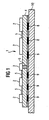
- the representation in Figure 1 is based on the fact that the current measuring resistor 9 twisted twice, that is S-shaped and thus can be seen three times in the sectional view. So at the Top of the ceramic circuit carrier 4 on a separately assembled component and the circuit carrier 4 altogether be made smaller.
- the relatively high temperature-related measurement error of the printed Current measuring resistor 9 is using the anyway existing temperature sensor 3 in the control unit 14 corrected. Via the circuit carrier 4 - and possibly the Via 6 - are the current measuring resistor 9 and Temperature sensor 3 thermally coupled, so that the temperature indication of the temperature sensor 3 to correct the resistance value of the current resistor 9 can be used. Are several current measuring resistors 9 for several hydraulic valves 16 provided, the temperature signal of a temperature sensor 3 used to correct all current measuring resistors 9 become.
- a power supply 12 supplies all components the transmission control 11 and protects it from short circuits and fault voltages.
- Resistors 8 are made as thick film resistors, so are also the temperature sensor 3 and the current measuring resistor 9 in advantageously formed as a thick-film resistor.
- Such temperature sensors are known, for example from IEEE Transactions and Components, Hybrides and Manufacturing Technology, Vol. CHMT-3, No. 4, December 1980, New York, USA "Thick-Film Thermistor and Its Applications" or JP 5135908.
- a temperature error of the printed current measuring resistor of can more than 10% by the circuit arrangement of the invention be compensated so far that the deviation of the measured Current is below 1%.
- the compensation takes place, for example digital in a microcontroller ⁇ C of the control unit 14.
- the dependence of the resistance value of the current measuring resistor 9 of the temperature is in the microcontroller Example saved as a characteristic.
- signal conditioning circuits 19 In which those supplied by various sensors 18 Signals are suppressed and processed before they are sent to Evaluation into control unit 14.
- the sensors 18 provide information about different pressures, speeds and positions and thus on the operating state of the transmission 17th
- the control unit 14 evaluates both external commands that a communication interface 20, as well as the Sensor signals, and then generates control signals. It controls communication, switches relays, regulates the hydraulic valves 16, records operating data and monitors the transmission 17 and the transmission control 11.
- Driver circuits 22 control external loads via relays, such as a lock that prevents not operated brake with the selector lever one speed step of the Gearbox is inserted.
- the Circuit arrangement 1 serves to regulate the coil current in particular for a hydraulic pressure control valve 16 of a motor vehicle transmission 17.
- Circuit carriers 4 produced are a thick-film resistor trained current measuring resistor 9 and a the transmission oil temperature sensing and with the current measuring resistor 9 thermally coupled temperature sensor 3 applied.
- the Signals from the current measuring resistor 9 and the temperature sensor 3 are fed to a control unit 14 in which the signal of Temperature sensor to compensate for the temperature-dependent Resistance value of the current measuring resistor 9 is used.
Landscapes
- Engineering & Computer Science (AREA)
- Physics & Mathematics (AREA)
- General Physics & Mathematics (AREA)
- Nonlinear Science (AREA)
- Automation & Control Theory (AREA)
- Chemical & Material Sciences (AREA)
- Combustion & Propulsion (AREA)
- Mechanical Engineering (AREA)
- General Engineering & Computer Science (AREA)
- Control Of Transmission Device (AREA)
- Measuring Instrument Details And Bridges, And Automatic Balancing Devices (AREA)
- Measurement Of Current Or Voltage (AREA)
Description
- Figur 1
- einen Schnitt durch eine erfindungsgemäße Schaltungsanordnung, und.
- Figur 2
- eine schematische Darstellung eines mit einer Schaltungsanordnung gemäß Figur 1 versehenen automatischen Getriebes
- 1
- Schaltungsanordnung
- 2
- Bauelement
- 3
- Temperatursensor oder -fühler
- 4
- Schaltungsträger, keramisch
- 5
- Leiterbahnen
- 6
- Durchkontaktierung
- 8
- Widerstände, in Dichschichttechnik aufgedruckt
- 9
- Strommeßwiderstand
- 10
- Wärmeableitplatte, Kühlplatte
- 11
- Getriebesteuerung
- 12
- Strömversorgung
- 14
- Steuergerät
- 15
- Stromregler
- 16
- Hydraulikventil
- 17
- automatisches Kraftfahrzeug-Getriebe
- 18
- Sensoren
- 19
- Signal-Aufbereitung(sschaltung)
- 20
- Kommunikatiosschnittstelle
- 22
- Treiberschaltung
- µC
- Mikrocontroller
Claims (4)
- Schaltungsanordnung (1) zum Regeln des einem elektromechanischen Bauteil in einem Kraftfahrzeug zugeführten Stromes, insbesondere des Spulenstromes für ein Hydraulikdruck-Regelventil (16) eines automatischen Kraftfahrzeuggetriebes (17), mit einem Schaltungsträger (4), der Leiterbahnen (5) und Bauelemente (2) zum Steuern des elektromechanischen Bauteiles und einen Strommeßwiderstand (9) auf weist, dessen Signal bei der Stromregelung ausgewertet wird, dadurch gekennzeichnet,daß auf dem aus einem Keramikwerkstoff hergestellten Schaltungsträger (4) der als Dickschichtwiderstand ausgebildete Strommeßwiderstand (9) und ein die Getriebeöltemperatur erfassender und mit dem Strommeßwiderstand (9) thermisch gekoppelter Temperatursensor (3) aufgebracht sind, unddaß die Signale des Strommeßwiderstands (9) und des Temperatursensors (3) einem Steuergerät (14) zugeführt werden, in dem das Signal des Temperatursensors (3) zur Kompensation des temperaturabhängigen Widerstandswert des Strommeßwiderstands (9) verwendet wird.
- Schaltungsanordnung nach Anspruch 1, dadurch gekennzeichnet, daß auf einer Seite des keramischen Schaltungsträgers (4) die Bauelemente (2) und auf der gegenüberliegenden Seite des Schaltungsträgers der Strommeßwiderstand (9) und weitere gedruckte Widerstände (8) und aufgebracht sind.
- Schaltungsanordnung nach einem der vorhergehenden Ansprüche, dadurch gekennzeichnet, daß der Temperatursensor (3) ein NTC-Widerstand ist.
- Schaltungsanordnung nach einem der vorhergehenden Ansprüche, dadurch gekennzeichnet, daß ein einziger den Temperaturverlauf mehrerer Strommeßwiderstände (9) kompensierender Temperatursensor (3) vorgesehen ist.
Applications Claiming Priority (3)
| Application Number | Priority Date | Filing Date | Title |
|---|---|---|---|
| DE19746056 | 1997-10-17 | ||
| DE19746056 | 1997-10-17 | ||
| PCT/DE1998/003038 WO1999021279A1 (de) | 1997-10-17 | 1998-10-16 | Schaltungsanordnung zum regeln des einem elektromechanischen bauteil in einem kraftfahrzeug zugeführten stromes |
Publications (2)
| Publication Number | Publication Date |
|---|---|
| EP1023773A1 EP1023773A1 (de) | 2000-08-02 |
| EP1023773B1 true EP1023773B1 (de) | 2002-01-09 |
Family
ID=7845921
Family Applications (1)
| Application Number | Title | Priority Date | Filing Date |
|---|---|---|---|
| EP98961014A Expired - Lifetime EP1023773B1 (de) | 1997-10-17 | 1998-10-16 | Schaltungsanordnung zum regeln des einem elektromechanischen bauteil in einem kraftfahrzeug zugeführten stromes |
Country Status (4)
| Country | Link |
|---|---|
| EP (1) | EP1023773B1 (de) |
| JP (1) | JP2001521159A (de) |
| DE (1) | DE59802861D1 (de) |
| WO (1) | WO1999021279A1 (de) |
Cited By (1)
| Publication number | Priority date | Publication date | Assignee | Title |
|---|---|---|---|---|
| DE102005051848A1 (de) * | 2005-10-28 | 2007-05-03 | Infineon Technologies Ag | Schaltungsanordnung zur Temperaturkompensation einer in einen Halbleiterkörper integrierten Messwiderstandsstruktur |
Families Citing this family (6)
| Publication number | Priority date | Publication date | Assignee | Title |
|---|---|---|---|---|
| DE10038976A1 (de) * | 1999-08-20 | 2001-02-22 | Luk Lamellen & Kupplungsbau | Kegelscheibenumschlingungsgetriebe |
| EP1229273B1 (de) * | 2001-02-02 | 2009-03-25 | Continental Automotive GmbH | Verfahren zur elektro-hydraulischen Steuerung eines Kraftfahrzeuggetriebes und elektro-hydraulische Steuerung für ein Kraftfahrzeuggetriebe |
| WO2003048790A1 (en) | 2001-12-03 | 2003-06-12 | Sanken Electric Co., Ltd. | Current detecting circuit and actuator driving apparatus |
| EP1721176B1 (de) * | 2003-12-10 | 2010-09-01 | Robert Bosch Gmbh | Verfahren und vorrichtung zur gleichstromversorgung eines elektrischen verbrauchers |
| DE102016216348B4 (de) | 2016-08-30 | 2025-03-27 | Continental Automotive Technologies GmbH | Messanordnung zur Strommessung |
| WO2023043463A1 (en) * | 2021-09-20 | 2023-03-23 | Google Llc | Device having integrated current sensors |
Citations (1)
| Publication number | Priority date | Publication date | Assignee | Title |
|---|---|---|---|---|
| US5159532A (en) * | 1988-11-09 | 1992-10-27 | Telefunken Electronic Gmbh | Electronic control unit with multiple hybrid circuit assemblies integrated on a single common ceramic carrier |
Family Cites Families (7)
| Publication number | Priority date | Publication date | Assignee | Title |
|---|---|---|---|---|
| DE2630958B2 (de) | 1976-07-07 | 1978-07-27 | Heliowatt Werke Elektrizitaets-Gesellschaft Mbh, 1000 Berlin | Fehlerkompensationsverfahren |
| JPS6047462B2 (ja) * | 1978-06-02 | 1985-10-22 | 株式会社日立製作所 | 電子制御燃料噴射装置の吸入空気量計測装置 |
| JPS60145438A (ja) * | 1983-09-07 | 1985-07-31 | Hitachi Ltd | 内燃機関の燃料制御装置 |
| US4836174A (en) * | 1987-02-06 | 1989-06-06 | Toyota Jidosha Kabushiki Kaisha | Engine control system |
| DE3811670A1 (de) * | 1988-04-07 | 1989-10-19 | Rexroth Mannesmann Gmbh | Verfahren zur kompensation der durch temperaturbedingte widerstandsaenderungen verursachten aenderung der stellkraft eines elektromagnetischen antriebs fuer ein proportionalventil |
| JPH05135908A (ja) | 1991-11-11 | 1993-06-01 | Matsushita Electric Ind Co Ltd | 接触型薄膜サーミスタ |
| DE4223338A1 (de) | 1992-07-16 | 1994-01-20 | Ant Nachrichtentech | Einrichtung zur Stromerfassung |
-
1998
- 1998-10-16 DE DE59802861T patent/DE59802861D1/de not_active Expired - Lifetime
- 1998-10-16 EP EP98961014A patent/EP1023773B1/de not_active Expired - Lifetime
- 1998-10-16 WO PCT/DE1998/003038 patent/WO1999021279A1/de not_active Ceased
- 1998-10-16 JP JP2000517486A patent/JP2001521159A/ja active Pending
Patent Citations (1)
| Publication number | Priority date | Publication date | Assignee | Title |
|---|---|---|---|---|
| US5159532A (en) * | 1988-11-09 | 1992-10-27 | Telefunken Electronic Gmbh | Electronic control unit with multiple hybrid circuit assemblies integrated on a single common ceramic carrier |
Cited By (3)
| Publication number | Priority date | Publication date | Assignee | Title |
|---|---|---|---|---|
| DE102005051848A1 (de) * | 2005-10-28 | 2007-05-03 | Infineon Technologies Ag | Schaltungsanordnung zur Temperaturkompensation einer in einen Halbleiterkörper integrierten Messwiderstandsstruktur |
| DE102005051848B4 (de) * | 2005-10-28 | 2008-08-21 | Infineon Technologies Ag | Schaltungsanordnung zur temperaturdriftkompensierten Strommessung |
| US7443178B2 (en) | 2005-10-28 | 2008-10-28 | Infineon Technologies Ag | Circuit arrangement of the temperature compensation of a measuring resistor structure |
Also Published As
| Publication number | Publication date |
|---|---|
| EP1023773A1 (de) | 2000-08-02 |
| DE59802861D1 (de) | 2002-02-28 |
| WO1999021279A1 (de) | 1999-04-29 |
| JP2001521159A (ja) | 2001-11-06 |
Similar Documents
| Publication | Publication Date | Title |
|---|---|---|
| DE19906276A1 (de) | Verfahren und Strommeßmodul zur Stromüberwachung in einem Stromversorgungssystem | |
| DE19701055B4 (de) | Halbleiter-Drucksensor | |
| DE102004041388A1 (de) | Drucksensorzelle und diese verwendende Drucksensorvorrichtung | |
| DE102008045722A1 (de) | Temperaturerfassungssystem | |
| EP0018013A1 (de) | Dehnungsmessstreifen - Brückenschaltung | |
| DE29513950U1 (de) | Getriebesteuerung für ein Kraftfahrzeug | |
| EP1494004B1 (de) | Differenzdrucksensor | |
| EP1442309A2 (de) | Verfahren und schaltungsanordnung zur erkennung eines defekts von halbleiterschaltelementen und deren verwendung in elektronischen bremskraft- und fahrdynamikreglern | |
| EP1023773A1 (de) | Schaltungsanordnung zum regeln des einem elektromechanischen bauteil in einem kraftfahrzeug zugeführten stromes | |
| DE10063070B4 (de) | Flußsensor des Wärmeerzeugungstyps | |
| EP1347274A1 (de) | Modulare Kraftmesszelle für eine Waage und Waage | |
| EP0955524A2 (de) | Luftmassensensor | |
| DE10013345B4 (de) | Einrichtung zum Messen eines durch eine Leiterbahn fließenden elektrischen Stroms und deren Anwendung | |
| EP0419611B1 (de) | Verfahren zum herstellen eines sensors zum bestimmen von druckkräften | |
| EP1046839A2 (de) | Elektronisches Steuergerät für ein Kraftfahrzeug-Automatikgetriebe und Verfahren zum Abgleichen eines Positionserkennungssensors | |
| DE4022697A1 (de) | Sensor | |
| DE10330047A1 (de) | Halbleitersensor für eine dynamische Größe | |
| EP1791048A1 (de) | Automatisierungssystem mit einem angeschlossenen RFID-identifizierten Sensor oder Aktor | |
| DE10324292A1 (de) | Messelement für einen Durchflusssensor, insbesondere einen Luftmassensensor für Brennkraftmaschinen | |
| EP1328770A1 (de) | Vorrichtung zur erfassung einer thermisch bedingten längenausdehnung eines maschinenteils | |
| EP4246113B1 (de) | Modular aufgebauter differenzdrucksensor | |
| DE102006014460B4 (de) | Galvanisch getrennter Gleichstromübertrager | |
| US6313977B1 (en) | Circuit configuration for regulating the current fed to an electromechanical component in a motor vehicle | |
| DE102009019774A1 (de) | Verfahren und Vorrichtung zur thermischen Überwachung von Ausfallprozessen | |
| DE10339789A1 (de) | Temperaturausgleichsvorrichtung für einen Drehmomentsensor |
Legal Events
| Date | Code | Title | Description |
|---|---|---|---|
| PUAI | Public reference made under article 153(3) epc to a published international application that has entered the european phase |
Free format text: ORIGINAL CODE: 0009012 |
|
| 17P | Request for examination filed |
Effective date: 20000404 |
|
| AK | Designated contracting states |
Kind code of ref document: A1 Designated state(s): DE FR GB IT |
|
| GRAG | Despatch of communication of intention to grant |
Free format text: ORIGINAL CODE: EPIDOS AGRA |
|
| GRAG | Despatch of communication of intention to grant |
Free format text: ORIGINAL CODE: EPIDOS AGRA |
|
| GRAH | Despatch of communication of intention to grant a patent |
Free format text: ORIGINAL CODE: EPIDOS IGRA |
|
| 17Q | First examination report despatched |
Effective date: 20010531 |
|
| GRAH | Despatch of communication of intention to grant a patent |
Free format text: ORIGINAL CODE: EPIDOS IGRA |
|
| GRAA | (expected) grant |
Free format text: ORIGINAL CODE: 0009210 |
|
| REG | Reference to a national code |
Ref country code: GB Ref legal event code: IF02 |
|
| AK | Designated contracting states |
Kind code of ref document: B1 Designated state(s): DE FR GB IT |
|
| PG25 | Lapsed in a contracting state [announced via postgrant information from national office to epo] |
Ref country code: GB Free format text: LAPSE BECAUSE OF FAILURE TO SUBMIT A TRANSLATION OF THE DESCRIPTION OR TO PAY THE FEE WITHIN THE PRESCRIBED TIME-LIMIT Effective date: 20020109 |
|
| GBV | Gb: ep patent (uk) treated as always having been void in accordance with gb section 77(7)/1977 [no translation filed] |
Effective date: 20020109 |
|
| REF | Corresponds to: |
Ref document number: 59802861 Country of ref document: DE Date of ref document: 20020228 |
|
| PLBI | Opposition filed |
Free format text: ORIGINAL CODE: 0009260 |
|
| PLBQ | Unpublished change to opponent data |
Free format text: ORIGINAL CODE: EPIDOS OPPO |
|
| GBT | Gb: translation of ep patent filed (gb section 77(6)(a)/1977) |
Effective date: 20020406 |
|
| 26 | Opposition filed |
Opponent name: WABCO GMBH & CO. OHG Effective date: 20020423 |
|
| ET | Fr: translation filed | ||
| PLBF | Reply of patent proprietor to notice(s) of opposition |
Free format text: ORIGINAL CODE: EPIDOS OBSO |
|
| PLBF | Reply of patent proprietor to notice(s) of opposition |
Free format text: ORIGINAL CODE: EPIDOS OBSO |
|
| PLAB | Opposition data, opponent's data or that of the opponent's representative modified |
Free format text: ORIGINAL CODE: 0009299OPPO |
|
| R26 | Opposition filed (corrected) |
Opponent name: WABCO GMBH Effective date: 20020423 |
|
| PLCK | Communication despatched that opposition was rejected |
Free format text: ORIGINAL CODE: EPIDOSNREJ1 |
|
| RAP2 | Party data changed (patent owner data changed or rights of a patent transferred) |
Owner name: CONTINENTAL AUTOMOTIVE GMBH |
|
| PLBN | Opposition rejected |
Free format text: ORIGINAL CODE: 0009273 |
|
| STAA | Information on the status of an ep patent application or granted ep patent |
Free format text: STATUS: OPPOSITION REJECTED |
|
| 27O | Opposition rejected |
Effective date: 20080603 |
|
| PLAB | Opposition data, opponent's data or that of the opponent's representative modified |
Free format text: ORIGINAL CODE: 0009299OPPO |
|
| PGFP | Annual fee paid to national office [announced via postgrant information from national office to epo] |
Ref country code: IT Payment date: 20101026 Year of fee payment: 13 Ref country code: GB Payment date: 20101021 Year of fee payment: 13 |
|
| REG | Reference to a national code |
Ref country code: FR Ref legal event code: TP |
|
| REG | Reference to a national code |
Ref country code: GB Ref legal event code: 732E Free format text: REGISTERED BETWEEN 20110825 AND 20110831 |
|
| GBPC | Gb: european patent ceased through non-payment of renewal fee |
Effective date: 20111016 |
|
| PG25 | Lapsed in a contracting state [announced via postgrant information from national office to epo] |
Ref country code: GB Free format text: LAPSE BECAUSE OF FAILURE TO SUBMIT A TRANSLATION OF THE DESCRIPTION OR TO PAY THE FEE WITHIN THE PRESCRIBED TIME-LIMIT Effective date: 20111016 Ref country code: IT Free format text: LAPSE BECAUSE OF NON-PAYMENT OF DUE FEES Effective date: 20111016 |
|
| PGFP | Annual fee paid to national office [announced via postgrant information from national office to epo] |
Ref country code: DE Payment date: 20121031 Year of fee payment: 15 Ref country code: FR Payment date: 20121031 Year of fee payment: 15 |
|
| REG | Reference to a national code |
Ref country code: DE Ref legal event code: R119 Ref document number: 59802861 Country of ref document: DE Effective date: 20140501 |
|
| REG | Reference to a national code |
Ref country code: FR Ref legal event code: ST Effective date: 20140630 |
|
| PG25 | Lapsed in a contracting state [announced via postgrant information from national office to epo] |
Ref country code: FR Free format text: LAPSE BECAUSE OF NON-PAYMENT OF DUE FEES Effective date: 20131031 Ref country code: DE Free format text: LAPSE BECAUSE OF NON-PAYMENT OF DUE FEES Effective date: 20140501 |