EP1022934A2 - Busleiterabschnitt für ein elektrisches Gerät - Google Patents
Busleiterabschnitt für ein elektrisches Gerät Download PDFInfo
- Publication number
- EP1022934A2 EP1022934A2 EP00100303A EP00100303A EP1022934A2 EP 1022934 A2 EP1022934 A2 EP 1022934A2 EP 00100303 A EP00100303 A EP 00100303A EP 00100303 A EP00100303 A EP 00100303A EP 1022934 A2 EP1022934 A2 EP 1022934A2
- Authority
- EP
- European Patent Office
- Prior art keywords
- bus conductor
- row
- conductor section
- circuit board
- board
- Prior art date
- Legal status (The legal status is an assumption and is not a legal conclusion. Google has not performed a legal analysis and makes no representation as to the accuracy of the status listed.)
- Granted
Links
Images



Classifications
-
- H—ELECTRICITY
- H01—ELECTRIC ELEMENTS
- H01R—ELECTRICALLY-CONDUCTIVE CONNECTIONS; STRUCTURAL ASSOCIATIONS OF A PLURALITY OF MUTUALLY-INSULATED ELECTRICAL CONNECTING ELEMENTS; COUPLING DEVICES; CURRENT COLLECTORS
- H01R9/00—Structural associations of a plurality of mutually-insulated electrical connecting elements, e.g. terminal strips or terminal blocks; Terminals or binding posts mounted upon a base or in a case; Bases therefor
- H01R9/22—Bases, e.g. strip, block, panel
- H01R9/24—Terminal blocks
- H01R9/26—Clip-on terminal blocks for side-by-side rail- or strip-mounting
- H01R9/2675—Electrical interconnections between two blocks, e.g. by means of busbars
-
- H—ELECTRICITY
- H05—ELECTRIC TECHNIQUES NOT OTHERWISE PROVIDED FOR
- H05K—PRINTED CIRCUITS; CASINGS OR CONSTRUCTIONAL DETAILS OF ELECTRIC APPARATUS; MANUFACTURE OF ASSEMBLAGES OF ELECTRICAL COMPONENTS
- H05K7/00—Constructional details common to different types of electric apparatus
- H05K7/14—Mounting supporting structure in casing or on frame or rack
- H05K7/1438—Back panels or connecting means therefor; Terminals; Coding means to avoid wrong insertion
- H05K7/1439—Back panel mother boards
- H05K7/1441—Back panel mother boards with a segmented structure
-
- Y—GENERAL TAGGING OF NEW TECHNOLOGICAL DEVELOPMENTS; GENERAL TAGGING OF CROSS-SECTIONAL TECHNOLOGIES SPANNING OVER SEVERAL SECTIONS OF THE IPC; TECHNICAL SUBJECTS COVERED BY FORMER USPC CROSS-REFERENCE ART COLLECTIONS [XRACs] AND DIGESTS
- Y10—TECHNICAL SUBJECTS COVERED BY FORMER USPC
- Y10S—TECHNICAL SUBJECTS COVERED BY FORMER USPC CROSS-REFERENCE ART COLLECTIONS [XRACs] AND DIGESTS
- Y10S439/00—Electrical connectors
- Y10S439/928—Modular electrically interengaging parts, e.g. stove with replaceable heating elements formed on coupling parts
Definitions
- the innovation relates to a bus conductor section for an electrical device modular structure for the control and / or monitoring of technical processes and / or for industrial and / or building automation, with at least one a mounting rail attachable connection module for external conductors and with a Series of disc-shaped base clamps, with each inside Connection modules the internal bus conductor section essentially parallel to Carrier rail runs.
- a generic bus conductor section for an electrical device is from EP 95 113 729 A2 known.
- the internal Bus conductor section as a continuous circuit board with conductor tracks attached to it is designed, serve to mountable terminal blocks on mounting rails Signal adaptation between a higher-level fieldbus and to the connection blocks connected initiators, field devices or the like.
- the terminal blocks are composed of functionally different connection or module disks, whereby between protective conductor washers, feed washers, supply / signal conductor washers and locking foot washers is distinguished.
- One or more connection blocks are over the internal bus conductor can be connected to a connection module for the fieldbus.
- the internal bus conductor section of this solution has the problem that with regard to an arbitrarily long series of module disks and module blocks different types within the connection module no sufficient variability given is.
- the innovation aims to address this problem constructively and structurally simple way to solve space-saving.
- bus conductor sections of the individual basic terminal supports are structurally separate from one another formed separately and each have a circuit board that is made by at least one Row of metal pins is interspersed, which on one side of the board in essentially vertical and on the opposite side of the board are aligned substantially parallel to the board, the at least one The row of pins extending perpendicular to the board is dimensioned such that its Pin row ends can be used directly for contacting a socket strip.
- the structural separation of the bus conductor sections of each module pane initially brings the advantage of almost any connectability of the bus conductor sections and thus increases the variability of the entire module system. It also brings the chosen structural design of the bus conductor section with a circuit board and the Board penetrating angle pins of special length with the advantage that separate plug elements for contacting a separate one or one to one Electronics circuit board molded connector plug can be omitted.
- the bus conductor sections of the individual base terminal supports each have a circuit board on which at least one row of angled metal pins is attached, which with one of its ends in substantially perpendicular and with their other ends substantially parallel to Board are, again the ends of the pins perpendicular to the board are dimensioned such that they can be used directly for contacting a socket strip are.
- This embodiment is particularly suitable for SMD connection technology.
- the signal paths of the bus conductor sections of adjacent modules are preferably such staggered connected that depending on the number of staggered Data lines can be easily recognized whether one or more in front of one Participant provided circuit boards on the base terminal support is available or not.
- Fig. 1 shows a module disk MS for a device not otherwise shown here Automation technology.
- the device includes a gateway (not shown here) which among other things the modular panels MS can be stacked.
- the module disc MS is included further module disks MS to a connection block of variable length put together.
- the module disc MS has a disc-shaped base clamp carrier according to FIG. 1 2 for locking the individual module on one (not here shown) mounting rail.
- the basic terminal support 2 is provided with plastic snap-in feet 4 provided with which the latching connection for Carrier rail can be produced.
- the base terminal support 2 comprises a lower one Base section 6, which is in an area above the mounting rail feet 4 and in addition to the mounting rail feet 4 extends on both sides beyond the mounting rail. In the base section 6 is in one lying away from the mounting rail Outside area a the basic terminal support 2 perpendicular to its main extension plane penetrating recess 8 for receiving the internal Bus conductor section 10 is provided, the forwarding of the bus conductor signals from Single module to single module and in the electronic circuit board 14 allowed.
- the electronic circuit board 14 is in the area which is approximately from the vertical to the center of the mounting rail to the internal one Bus conductor section 10 extends in the base terminal support 2, a circumferential recess 12 trained.
- the electronic circuit board 14 is with a (not here shown) electronic circuit for processing / forwarding to each Electronics circuit board 14 provided signals.
- the area is the base section 6 with three further openings lying next to one another 16, 17, 18 provided, each perpendicular to the main disc or module plane Penetrate base terminal support 2 and of which two openings 16, 17 with as Cross bridges designed contact elements 20, 22 are provided, which a Allow the assigned potentials to be passed on from module to module.
- the further opening 18 is used - like other openings not described here in the Basic terminal support - only the material savings. From the cross bridges 20, 22 these potentials are in the circuit board and / or via a suitable separate or molded on the electronics circuit board connector 24 to the connections to the Busbars in the basic terminal support 2 and via these to the connection levels A, B, C of the module disc MS out.
- the recess 12 is at the end facing away from the mounting rail Individual modules from a web 26 projecting perpendicularly from the base section limited, that on its side facing the mounting rail 4 with an insertion groove 28 for inserting the electronic circuit board 14 and an electronics housing 29 is provided.
- connection section 30 Approximately at the end of the base terminal support 2 opposite the web 26 is a vertically upwardly projecting connection section 30 on the base section 6 integrally formed with the six connections A1 arranged in two rows of three, A2, ... is provided. Openings 34 with a square cross section next Port openings 32 for ports A1, A2, B1, B2 ... allow insertion a screwdriver for opening the spring contact elements arranged in the connection section 30 36.
- the conductive connection between the contact springs 36 of the connections A, B, C, ... and the electronic circuit board 14 is by means of busbars (shown here: SP for the plus potential and SSI for the signal, not recognizable: SM for the negative Potential).
- the busbars SM, SP run from the contact springs 36 in lateral grooves / recesses 42 of the base element 2 substantially U-shaped on both main outer surfaces of the basic terminal support 2.
- Below the Recess 12 for the electronic circuit board are the busbars upwards angled and run to the circumferential recess 12, which in this area with six connection openings 44 lying side by side in two rows for Attaching the device connector 24 to the electronic circuit board and / or the PCB edge is provided.
- a cover housing 46 made of plastic can be placed over the connection section 30, which has openings 48 which are connected to the connection openings 32 and Openings 34 correspond.
- area of the recess 12 of the basic terminal support 2 the cover is further provided with a lateral groove 50, which in cooperation with the groove 28, the electronic circuit board 14 and the Electronics circuit board 14 accommodates protective housing 29, which in the direction of insertion SR can be placed on the base terminal support 2.
- the base terminal support 2 or the module disk MS comprises the following functional areas in the area of the recess 12 on / below the base wall 52 of the recess 12 (viewed from the web 26 inwards towards the mounting rail): - Module bus (opening) BUS / 8 - Labeling channel (for one or two signs) 54 - Lateral locking hook as a connection to the neighboring terminal with opening 57 for actuating the locking hook from above 57 - FE contact (functional earth) 58 - Potential guidance contact opening 59 - Plug sockets / connection openings 44.
- PE- potential leads a recess 62 for a coding element 64 in a particularly space-saving manner intended.
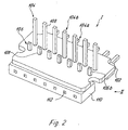
- each base terminal carrier inserted into the opening 8 2 each has a circuit board 102 according to FIG. 2, which is made up of a row 104 metal pins 108 is penetrated, which on one side of the board 102 (side I) substantially vertical and on the opposite side of the board 102 (side II) are aligned substantially parallel to the circuit board 102.
- a second row 106 of metal pins 108 also just penetrates the circuit board, but only with short soldering ends 106b.
- the other end 104a of this row of pins 106 lies with the Pin row ends 104a in one plane, the ends of the pin rows 104, 106 are in the Facing away from each other.
- the pin row ends 104a of one row 104 of the Metal pins 108 protrude laterally over the edge of the board 102.
- FIG. 4 and 5 illustrate the advantageous in interaction with Fig. 1 and Fig. 7 Position of the bus conductor sections 10 in the base terminal support 2.
- the bus conductor sections 10 are inserted into the opening 8, where the row of pins 104 against one of the Basic terminal support 2 wall 118 protruding vertically upwards for protection the pins and the corresponding area of the electronic circuit board 14 abuts.
- a plastic molded part 120 is attached the function of a protective and cover plate also inserted into the opening 8, where it locks into the base terminal support 2 with locking feet 122.
- the lower part 120a serves as over the edge of the terminal support 2 protruding protective cover for the pin row ends 104a and for engagement in the opening 8 of an adjacent base terminal carrier 2.
- the base terminal support 2 are insertable and since the board 102 with a stop edge 124 to stop is provided on a counter edge of the base terminal support 2, the result is special advantage that the bus conductor section 10 when inserting or Pull the electronics - as well as when unlocking the base terminal support 2 from neighboring basic terminal support 2 on the locking hook - in the basic terminal support 2 is securely fixed.
- FIG. 8 illustrates the integration of the internal bus conductor section 10 in the comprehensive module system.
- An external is connected to a gateway Fieldbus possible.
- Both the power supply of the gateway and the Connection modules or the module disks MS and the forwarding of the Data bus from the gateway to the electronic circuit boards 14 of the individual basic terminal carriers 2 or the module disks MS and module blocks are both in a block as well as in a pane structure by means of the internal shown Bus conductor sections 10.
- the two rows of connector pins 108 are over the circuit board 102 interconnected such that these connections potential and signal paths from bus conductor section 10 to bus conductor section as well as potential and signal paths from the bus conductor section 10 to the electronic circuit boards 14 of the basic terminal support 2 form.
- FIGS. 9a and 9b With a further offset data line in the direction corresponding to FIG. 9a even in front of the attached electronic circuit board 14 of the participant (N) in each case two removed electronic circuit boards or two participant (N-1 or N-2 or N-1 and N-2 together) recognizable.
- the variants of FIGS. 9a and 9b are not combinable with each other.
Landscapes
- Engineering & Computer Science (AREA)
- Microelectronics & Electronic Packaging (AREA)
- Coupling Device And Connection With Printed Circuit (AREA)
- Connections Arranged To Contact A Plurality Of Conductors (AREA)
- Patch Boards (AREA)
- Inverter Devices (AREA)
- Multi-Conductor Connections (AREA)
- Structure Of Telephone Exchanges (AREA)
Abstract
Description
| - | Modulbus(öffnung) | BUS/8 |
| - | Kennzeichnungskanal (für ein oder zwei Schilder) | 54 |
| - | seitlicher Rasthaken als Verbindung zur Nachbarklemme mit Öffnung 57 zur Betätigung des Rasthakens von oben | 57 |
| - | FE-Kontakt (Funktionserde) | 58 |
| - | Potentialführungs-Kontaktierungsöffnung | 59 |
| - | Steckerbuchsen/Anschlußöffnungen | 44. |

- Modulscheibe
- MS
- Anschlußebenen
- A, B, C, ...
- Mehrfachanschlüsse
- A1, A2, ..., B1, B2, ...
- Schutzerde
- PE
- Funktionserde
- FE
- Stromzuführschienen
- SP, SSI, SPE
- Steckrichtung
- SR
- Basis-Klemmenträger
- 2
- Kunststoff-Rastfüße
- 4
- Basisabschnitt
- 6
- Busleiteröffnung
- 8
- Busleiterabschnitt
- 10
- Umfangs-Ausnehmung
- 12
- Elektronik-Leiterplatte
- 14
- Öffnungen
- 16, 17, 18
- Kontaktelemente
- 20, 22
- Stecker
- 24
- Steg
- 26
- Einschubnut
- 28
- Elektronikgehäuse
- 29
- Anschlußabschnitt
- 30
- Runde Öffnungen
- 32
- Quadratische Öffnungen
- 34
- Feder-Kontaktelemente
- 36
- Öffnung
- 38
- Kontaktelement
- 40
- Aussparungen
- 42
- Anschlußöffnungen
- 44
- Abdeckgehäuse
- 46
- Öffnungen
- 48
- Nut
- 50
- Grundwandung
- 52
- Kennzeichnungskanal
- 54
- Öffnung
- 57
- FE-Kontakt
- 58
- Potential-Kontaktierungsöffnung
- 59
- Ausnehmung
- 62
- Kodierlelement
- 64
- Platine
- 102
- Stiftreihen
- 104, 106
- Metallstifte
- 108
- Steckerbuchsenleiste
- 110
- Steckerbuchsenöffnungen
- 112
- Steckerstift-Gehäuseleiste
- 114
- Buchsenleiste
- 116
- Wandung
- 118
- Kunststofformteil
- 120
- Rastfuß
- 122
- Anschlagkante
- 124
Claims (9)
- Busleiterabschnitt für ein elektrisches Gerät mit modularem Aufbau zur Steuerung und/oder Überwachung technischer Prozesse und/oder zur Industrie- und/oder Gebäudeautomatisierung,a) mit wenigstens einem auf eine Tragschiene aufsetzbaren Anschlußmodul (M) mit Anschlüssen (A1, A2, B1, ...) für externe Leiter und mit einer Reihung scheibenförmiger Basis-Klemmenträger (2),b) wobei innerhalb jedes Anschlußmodules (M) der interne Busleiterabschnitt (10) im wesentlichen parallel zur Tragschiene verläuft,
dadurch gekennzeichnet,c) daß die Busleiterabschnitte (10) der einzelnen Basis-Klemmenträger (2) baulich voneinander getrennt ausgebildet sind und jeweils eine Platine (102) aufweisen, die von wenigstens einer Reihe (104) von Metallstiften (108) durchsetzt ist, welche auf der einen Seite der Platine (102) im wesentlichen senkrecht und auf der gegenüberliegenden Seite der Platine (102) im wesentlichen parallel zur Platine (102) ausgerichtet sind,d) wobei die wenigstens eine senkrecht zur Platine erstreckende Stiftreihe (104) derart bemessen ist, daß ihre Stiftreihenenden (104b) direkt zum Kontaktieren einer Buchsenleiste (116) nutzbar sind. - Busleiterabschnitt nach dem Oberbegriff des Anspruches 1, dadurch gekennzeichnet, daßdie Busleiterabschnitte (10) der einzelnen Basis-Klemmenträger (2) baulich voneinander getrennt ausgebildet sind und jeweils eine Platine (102) aufweisen, auf die wenigstens eine Reihe (104) abgewinkelter Metallstifte (108) aufgesetzt ist, welche mit ihren einen Enden im wesentlichen senkrecht und mit ihren anderen Enden im wesentlichen parallel zur Platine (102) ausgerichtet sind,wobei die senkrecht zur Platine stehenden Stiftreihenenden (104b) derart bemessen sind, daß sie direkt zum Kontaktieren einer Buchsenleiste (116) nutzbar sind.
- Busleiterabschnitt nach einem der vorstehenden Ansprüche, dadurch gekennzeichnet, daß die Stiftreihenenden (104a) der einen Reihe (104) der Metallstifte (108) seitlich über den Rand der Platine (102) vorstehen.
- Busleiterabschnitt nach einem der vorstehenden Ansprüche, dadurch gekennzeichnet, daß auf Stiftreihenenden (106a) einer parallel zur Platine verlaufenden Reihe (106) von Metallstiften (108) eine Steckerbuchsenleiste (110) und auf die Stiftreihenenden (104a) der anderen parallel zur Platine verlaufenden Reihe (104) von Metallstiften (108) eine Steckerstiftgehäuse-Leiste (114) aufgesetzt ist, wobei bei nebeneinanderliegenden Basis-Klemmenträgern (2) die Enden (104a) der einen Reihe (104) der Metallstifte (108) in die Steckerbuchsenleiste (110) des Busleiterabschnittes (10') des jeweils benachbarten Basis-Klemmenträgers (2) eingreifen.
- Busleiterabschnitt nach einem der vorstehenden Ansprüche, dadurch gekennzeichnet, daß die beiden Stiftreihen (104, 106) über die Platine (102) miteinander verbunden sind, so daß Potential- und Signalwege von Busleiterabschnitt (10) zu Busleiterabschnitt (10') als auch vom Busleiterabschnitt (10) zu den Elektronik-Leiterplatten (14) der Basis-Klemmenträger (2) gebildet werden.
- Busleiterabschnitt nach einem der vorstehenden Ansprüche, dadurch gekennzeichnet, daß ein Teil der Signalwege der Busleiterabschnitte (10) benachbarter Module derart versetzt miteinander verbunden ist, daß in Abhängigkeit von der Anzahl der versetzten Datenleitungen erkennbar ist, ob eine oder mehrere vor einem Teilnehmer vorgesehene Leiterplatten (14) auf dem Basis-Klemmenträger (2) vorhanden ist oder nicht.
- Busleiterabschnitt nach einem der vorstehenden Ansprüche, dadurch gekennzeichnet, daß die Busleiterabschnitte (10) in der Öffnung (8) des Basis-Klemmenträgers zwischen einer Wandung (118) des Basis-Klemmenträgers (2) und einem in die Öffnung (8) einschiebbaren Kunststofformteil (120) mit der Funktion einer Schutz- und Abdeckplatte festgelegt sind.
- Busleiterabschnitt nach einem der vorstehenden Ansprüche, dadurch gekennzeichnet, daß die Busleiterabschnitte (10) in die Busleiteröffnung (8) des Basis-Klemmenträgers (2) seitlich, vorzugsweise aus Richtung eines Gateways einschiebbar sind.
- Busleiterabschnitt nach einem der vorstehenden Ansprüche, dadurch gekennzeichnet, daß die Platine mit einer Anschlagkante (124) zum Anschlag an einer Gegenkante des Basis-Klemmenträgers (2) versehen ist.
Applications Claiming Priority (2)
| Application Number | Priority Date | Filing Date | Title |
|---|---|---|---|
| DE29901194U DE29901194U1 (de) | 1999-01-25 | 1999-01-25 | Busleiterabschnitt für ein elektrisches Gerät |
| DE29901194U | 1999-01-25 |
Publications (3)
| Publication Number | Publication Date |
|---|---|
| EP1022934A2 true EP1022934A2 (de) | 2000-07-26 |
| EP1022934A3 EP1022934A3 (de) | 2000-11-22 |
| EP1022934B1 EP1022934B1 (de) | 2006-03-22 |
Family
ID=8068412
Family Applications (1)
| Application Number | Title | Priority Date | Filing Date |
|---|---|---|---|
| EP00100303A Expired - Lifetime EP1022934B1 (de) | 1999-01-25 | 2000-01-07 | Busleiterabschnitt für ein elektrisches Gerät |
Country Status (5)
| Country | Link |
|---|---|
| US (1) | US6241561B1 (de) |
| EP (1) | EP1022934B1 (de) |
| AT (1) | ATE321441T1 (de) |
| DE (2) | DE29901194U1 (de) |
| ES (1) | ES2255901T3 (de) |
Cited By (1)
| Publication number | Priority date | Publication date | Assignee | Title |
|---|---|---|---|---|
| DE20103978U1 (de) * | 2001-03-07 | 2002-07-11 | Weidmüller Interface GmbH & Co., 32760 Detmold | Elektrisches Gerät mit Busleiterabschnitt |
Families Citing this family (24)
| Publication number | Priority date | Publication date | Assignee | Title |
|---|---|---|---|---|
| DE19964157A1 (de) * | 1999-01-25 | 2000-10-05 | Weidmueller Interface | Elektrisches Gerät |
| JP3130021B1 (ja) * | 1999-08-06 | 2001-01-31 | 盟友技研株式会社 | 中継接続装置 |
| DE29916302U1 (de) * | 1999-09-16 | 2001-03-01 | Weidmüller Interface GmbH & Co, 32760 Detmold | Busleiterabschnitt für ein elektrisches Gerät |
| EP1119229A1 (de) * | 2000-01-07 | 2001-07-25 | Weidmüller Interface GmbH & Co. | Kodiertes elektrisches Gerät |
| DE20009207U1 (de) * | 2000-05-22 | 2001-09-27 | CEAG Sicherheitstechnik GmbH, 59494 Soest | Einrichtung zur Signalübertragung |
| AU2002222447A1 (en) * | 2000-12-05 | 2002-06-18 | Aprion Digital Ltd. | Board integrated resilient contact elements array and method of fabrication |
| US6572403B2 (en) | 2001-01-22 | 2003-06-03 | National Instruments Corporation | Expansion plug apparatus for connecting a plurality of terminal blocks |
| DE10259415A1 (de) | 2002-12-19 | 2004-07-08 | Demag Ergotech Gmbh | Technologie-Platine mit modularer SPS-Integration und Erweiterung |
| US8734421B2 (en) | 2003-06-30 | 2014-05-27 | Johnson & Johnson Consumer Companies, Inc. | Methods of treating pores on the skin with electricity |
| DE102005003199A1 (de) * | 2004-08-24 | 2006-03-02 | Weidmüller Interface GmbH & Co. KG | Montage- und Anschluß-System für elektrische Geräte |
| DE102005040657A1 (de) * | 2005-08-26 | 2007-03-15 | Phoenix Contact Gmbh & Co. Kg | Elektrische Anschlussklemme |
| DE202007005373U1 (de) * | 2007-04-12 | 2008-08-21 | Weidmüller Interface GmbH & Co. KG | Reihenklemmensystem |
| DE202007011112U1 (de) | 2007-08-09 | 2007-11-15 | Mc Technology Gmbh | Adapterplatte, Steckfassung und Vorrichtung zur Verbindung einer elektronischen Steuerung mit ihren Anschlussleitungen |
| US20120089232A1 (en) | 2009-03-27 | 2012-04-12 | Jennifer Hagyoung Kang Choi | Medical devices with galvanic particulates |
| WO2011069537A1 (en) * | 2009-12-08 | 2011-06-16 | Abb Technology Ag | I/o module |
| DE202011050612U1 (de) | 2011-07-01 | 2012-10-09 | Weidmüller Interface GmbH & Co. KG | Leiterplatte mit Kontakten |
| DE102011086331A1 (de) | 2011-11-15 | 2013-05-16 | MCQ TECH GmbH | Anschlussklemme |
| US9576762B2 (en) | 2015-04-03 | 2017-02-21 | Eaton Corporation | Electrical switching apparatus and secondary disconnect assembly with error-proofing features therefor |
| US9336977B1 (en) | 2015-04-03 | 2016-05-10 | Eaton Corporation | Electrical switching apparatus and secondary disconnect assembly with terminal retention and correction features therefor |
| US9570261B2 (en) | 2015-04-03 | 2017-02-14 | Eaton Corporation | Electrical switching apparatus and secondary disconnect assembly with contact alignment features therefor |
| US9396889B1 (en) | 2015-04-03 | 2016-07-19 | Eaton Corporation | Electrical switching apparatus and secondary disconnect assembly with cradle assembly alignment and positioning features therefor |
| BE1027224B1 (de) | 2019-04-24 | 2020-11-23 | Phoenix Contact Gmbh & Co | Modularer Switch zum Einsatz in einem Datenübertragungs- und Steuerungssystem |
| DE102019127195A1 (de) | 2019-10-09 | 2021-04-15 | Phoenix Contact Gmbh & Co. Kg | Modulares Interfacesystem zum Anschließen einer Steuerungseinrichtung und von Feldgeräte |
| DE102021106522A1 (de) | 2020-03-27 | 2021-09-30 | Phoenix Contact Gmbh & Co. Kg | Backplanemodul zum elektrischen Verbinden mehrerer Funktionsmodule und modular aufgebautes Kommunikationssystem |
Family Cites Families (16)
| Publication number | Priority date | Publication date | Assignee | Title |
|---|---|---|---|---|
| US3172014A (en) * | 1962-08-27 | 1965-03-02 | Gen Electric | Electric control device panel assembly with locking strip |
| US4401351A (en) * | 1981-09-28 | 1983-08-30 | Advant Corporation | Expandable card cage |
| US4477862A (en) * | 1982-05-19 | 1984-10-16 | Gould Inc. | Backplane connector |
| DE3608752C1 (en) | 1986-03-15 | 1987-05-07 | Kostal Leopold Gmbh & Co Kg | Centralised electrical system for motor vehicles |
| ATE95969T1 (de) | 1988-10-18 | 1993-10-15 | Weidmueller Interface | Mehrfachsignaluebertragungsgeraet. |
| EP0396808B1 (de) | 1989-05-12 | 1994-09-28 | Weidmüller Interface GmbH & Co. | Reihenklemmenanordnung |
| DE4121836C2 (de) | 1991-07-02 | 1994-07-07 | Weidmueller C A Gmbh Co | Reihenklemme mit Aufsteckmodul |
| DE4325614C2 (de) | 1993-07-30 | 1995-08-31 | Weidmueller Interface | Reihenklemmenanordnung mit Überspannungsschutzorganen |
| EP0661915A1 (de) | 1993-12-28 | 1995-07-05 | RKC Instruments Inc. | Modular-Steuersystem |
| DE4438800C1 (de) | 1994-10-31 | 1996-01-18 | Weidmueller Interface | Anschlußklemmenblock mit Elektronikmodul |
| DE4438804C1 (de) | 1994-10-31 | 1996-03-28 | Weidmueller Interface | Modulare Steuerungsanlage mit Busleiter z. B. zur Gebäudeautomatisierung |
| DE4438801C1 (de) | 1994-10-31 | 1996-01-04 | Weidmueller Interface | Modulare Steuerungsanlage |
| DE19610559A1 (de) * | 1996-03-18 | 1997-09-25 | Siemens Ag | Speicherprogrammierbare Steuerung |
| DE19651962A1 (de) | 1996-12-13 | 1998-06-18 | Siemens Ag | Kaskadierbares Kontaktsystem mit Unterbrechungs- und Einspeisemöglichkeit an jedem Kontaktelement |
| DE19710768C2 (de) | 1997-03-16 | 1999-11-11 | Phoenix Contact Gmbh & Co | Elektrisches oder elektronisches Gerät |
| DE19718996C1 (de) | 1997-05-06 | 1998-06-04 | Phoenix Contact Gmbh & Co | Elektrisches oder elektronisches Gerät |
-
1999
- 1999-01-25 DE DE29901194U patent/DE29901194U1/de not_active Expired - Lifetime
-
2000
- 2000-01-07 AT AT00100303T patent/ATE321441T1/de active
- 2000-01-07 EP EP00100303A patent/EP1022934B1/de not_active Expired - Lifetime
- 2000-01-07 DE DE50012417T patent/DE50012417D1/de not_active Expired - Lifetime
- 2000-01-07 ES ES00100303T patent/ES2255901T3/es not_active Expired - Lifetime
- 2000-01-24 US US09/489,965 patent/US6241561B1/en not_active Expired - Lifetime
Cited By (1)
| Publication number | Priority date | Publication date | Assignee | Title |
|---|---|---|---|---|
| DE20103978U1 (de) * | 2001-03-07 | 2002-07-11 | Weidmüller Interface GmbH & Co., 32760 Detmold | Elektrisches Gerät mit Busleiterabschnitt |
Also Published As
| Publication number | Publication date |
|---|---|
| ES2255901T3 (es) | 2006-07-16 |
| EP1022934B1 (de) | 2006-03-22 |
| ATE321441T1 (de) | 2006-04-15 |
| EP1022934A3 (de) | 2000-11-22 |
| US6241561B1 (en) | 2001-06-05 |
| DE50012417D1 (de) | 2006-05-11 |
| DE29901194U1 (de) | 1999-05-20 |
Similar Documents
| Publication | Publication Date | Title |
|---|---|---|
| EP1022934B1 (de) | Busleiterabschnitt für ein elektrisches Gerät | |
| EP1022809B1 (de) | Elektrisches Gerät | |
| EP0709932B1 (de) | Modulare Steuerungsanlage mit Busleiter z. B. zur Gebäudeautomatisierung | |
| EP0712267B1 (de) | Modulare Steuerungsanlage mit integriertem Feldbusanschluss | |
| DE3843664C2 (de) | ||
| DE19902745B4 (de) | Elektrisches Gerät | |
| EP0452658A1 (de) | Anschlusseinrichtung für die Hausleittechnik | |
| DE3805158A1 (de) | Reihenklemme zur zweileiter-stromversorgung von elektrischen oder elektronischen bauelementen, insbesondere initiatoren | |
| DE60212232T2 (de) | Verbinderdose | |
| EP1239544B1 (de) | Elektrisches Gerät mit Busleiterabschnitt | |
| DE202010004408U1 (de) | Reihung von Anschlussmodulen | |
| EP3123844B1 (de) | Busfähiges aneinanderreihbares anschluss- und/oder funktionsmodul | |
| EP0881396B1 (de) | Vorrichtung zum elektrischen Anschluss von gruppiert angeordneten elektrischen Elementen | |
| DE19964150A1 (de) | Kodiervorrichtung zur Kodierung eines elektrischen Gerätes | |
| EP0739060B1 (de) | Steckverbinder | |
| EP0222030A1 (de) | Initiatorklemmenblock | |
| DE3943752C2 (de) | Pneumatische oder hydraulische Ventileinheit | |
| EP1085605B1 (de) | Busleiterabschnitt für ein elektrisches Gerät | |
| DE102015110223B4 (de) | Baugruppe einer Klemmeneinrichtung zum Anschließen von elektrischen Leitern | |
| EP1365478B1 (de) | Modulreihung und Adaptermodul | |
| DE19902811C1 (de) | Kodiervorrichtung und Kodierverfahren zur Kodierung eines elektrischen Gerätes | |
| DE19700057C2 (de) | Datenschiene für den Europäischen Installationsbus (EIB) | |
| EP0746064B1 (de) | Anschlussklemmenleiste für Leiterplatten | |
| EP1052752B1 (de) | Vorrichtung zur Aufnahme von wenigstens zwei elektrischen Bauteilen, wie Steckdosen, Schalter, Elektronikeinheiten und dgl. | |
| EP0980199B1 (de) | Türanlage, insbesondere Türsprechanlage |
Legal Events
| Date | Code | Title | Description |
|---|---|---|---|
| PUAI | Public reference made under article 153(3) epc to a published international application that has entered the european phase |
Free format text: ORIGINAL CODE: 0009012 |
|
| AK | Designated contracting states |
Kind code of ref document: A2 Designated state(s): AT BE CH CY DE DK ES FI FR GB GR IE IT LI LU MC NL PT SE |
|
| AX | Request for extension of the european patent |
Free format text: AL;LT;LV;MK;RO;SI |
|
| PUAL | Search report despatched |
Free format text: ORIGINAL CODE: 0009013 |
|
| AK | Designated contracting states |
Kind code of ref document: A3 Designated state(s): AT BE CH CY DE DK ES FI FR GB GR IE IT LI LU MC NL PT SE |
|
| AX | Request for extension of the european patent |
Free format text: AL;LT;LV;MK;RO;SI |
|
| 17P | Request for examination filed |
Effective date: 20001216 |
|
| AKX | Designation fees paid |
Free format text: AT BE CH CY DE DK ES FI FR GB GR IE IT LI LU MC NL PT SE |
|
| GRAP | Despatch of communication of intention to grant a patent |
Free format text: ORIGINAL CODE: EPIDOSNIGR1 |
|
| GRAS | Grant fee paid |
Free format text: ORIGINAL CODE: EPIDOSNIGR3 |
|
| GRAA | (expected) grant |
Free format text: ORIGINAL CODE: 0009210 |
|
| AK | Designated contracting states |
Kind code of ref document: B1 Designated state(s): AT BE CH CY DE DK ES FI FR GB GR IE IT LI LU MC NL PT SE |
|
| PG25 | Lapsed in a contracting state [announced via postgrant information from national office to epo] |
Ref country code: IT Free format text: LAPSE BECAUSE OF FAILURE TO SUBMIT A TRANSLATION OF THE DESCRIPTION OR TO PAY THE FEE WITHIN THE PRESCRIBED TIME-LIMIT;WARNING: LAPSES OF ITALIAN PATENTS WITH EFFECTIVE DATE BEFORE 2007 MAY HAVE OCCURRED AT ANY TIME BEFORE 2007. THE CORRECT EFFECTIVE DATE MAY BE DIFFERENT FROM THE ONE RECORDED. Effective date: 20060322 Ref country code: NL Free format text: LAPSE BECAUSE OF FAILURE TO SUBMIT A TRANSLATION OF THE DESCRIPTION OR TO PAY THE FEE WITHIN THE PRESCRIBED TIME-LIMIT Effective date: 20060322 Ref country code: IE Free format text: LAPSE BECAUSE OF FAILURE TO SUBMIT A TRANSLATION OF THE DESCRIPTION OR TO PAY THE FEE WITHIN THE PRESCRIBED TIME-LIMIT Effective date: 20060322 |
|
| REG | Reference to a national code |
Ref country code: GB Ref legal event code: FG4D Free format text: NOT ENGLISH |
|
| REG | Reference to a national code |
Ref country code: CH Ref legal event code: NV Representative=s name: ISLER & PEDRAZZINI AG Ref country code: CH Ref legal event code: EP |
|
| REG | Reference to a national code |
Ref country code: IE Ref legal event code: FG4D Free format text: LANGUAGE OF EP DOCUMENT: GERMAN |
|
| REF | Corresponds to: |
Ref document number: 50012417 Country of ref document: DE Date of ref document: 20060511 Kind code of ref document: P |
|
| GBT | Gb: translation of ep patent filed (gb section 77(6)(a)/1977) |
Effective date: 20060512 |
|
| PG25 | Lapsed in a contracting state [announced via postgrant information from national office to epo] |
Ref country code: DK Free format text: LAPSE BECAUSE OF FAILURE TO SUBMIT A TRANSLATION OF THE DESCRIPTION OR TO PAY THE FEE WITHIN THE PRESCRIBED TIME-LIMIT Effective date: 20060622 Ref country code: SE Free format text: LAPSE BECAUSE OF FAILURE TO SUBMIT A TRANSLATION OF THE DESCRIPTION OR TO PAY THE FEE WITHIN THE PRESCRIBED TIME-LIMIT Effective date: 20060622 |
|
| REG | Reference to a national code |
Ref country code: ES Ref legal event code: FG2A Ref document number: 2255901 Country of ref document: ES Kind code of ref document: T3 |
|
| PG25 | Lapsed in a contracting state [announced via postgrant information from national office to epo] |
Ref country code: PT Free format text: LAPSE BECAUSE OF FAILURE TO SUBMIT A TRANSLATION OF THE DESCRIPTION OR TO PAY THE FEE WITHIN THE PRESCRIBED TIME-LIMIT Effective date: 20060822 |
|
| NLV1 | Nl: lapsed or annulled due to failure to fulfill the requirements of art. 29p and 29m of the patents act | ||
| ET | Fr: translation filed | ||
| REG | Reference to a national code |
Ref country code: IE Ref legal event code: FD4D |
|
| PLBE | No opposition filed within time limit |
Free format text: ORIGINAL CODE: 0009261 |
|
| STAA | Information on the status of an ep patent application or granted ep patent |
Free format text: STATUS: NO OPPOSITION FILED WITHIN TIME LIMIT |
|
| PG25 | Lapsed in a contracting state [announced via postgrant information from national office to epo] |
Ref country code: MC Free format text: LAPSE BECAUSE OF NON-PAYMENT OF DUE FEES Effective date: 20070131 |
|
| 26N | No opposition filed |
Effective date: 20061227 |
|
| REG | Reference to a national code |
Ref country code: CH Ref legal event code: PCAR Free format text: ISLER & PEDRAZZINI AG;POSTFACH 1772;8027 ZUERICH (CH) |
|
| BERE | Be: lapsed |
Owner name: WEIDMULLER INTERFACE G.M.B.H. & CO. Effective date: 20070131 |
|
| PG25 | Lapsed in a contracting state [announced via postgrant information from national office to epo] |
Ref country code: BE Free format text: LAPSE BECAUSE OF NON-PAYMENT OF DUE FEES Effective date: 20070131 |
|
| PG25 | Lapsed in a contracting state [announced via postgrant information from national office to epo] |
Ref country code: GR Free format text: LAPSE BECAUSE OF FAILURE TO SUBMIT A TRANSLATION OF THE DESCRIPTION OR TO PAY THE FEE WITHIN THE PRESCRIBED TIME-LIMIT Effective date: 20060623 |
|
| PG25 | Lapsed in a contracting state [announced via postgrant information from national office to epo] |
Ref country code: FI Free format text: LAPSE BECAUSE OF FAILURE TO SUBMIT A TRANSLATION OF THE DESCRIPTION OR TO PAY THE FEE WITHIN THE PRESCRIBED TIME-LIMIT Effective date: 20060322 |
|
| PG25 | Lapsed in a contracting state [announced via postgrant information from national office to epo] |
Ref country code: LU Free format text: LAPSE BECAUSE OF NON-PAYMENT OF DUE FEES Effective date: 20070107 Ref country code: CY Free format text: LAPSE BECAUSE OF FAILURE TO SUBMIT A TRANSLATION OF THE DESCRIPTION OR TO PAY THE FEE WITHIN THE PRESCRIBED TIME-LIMIT Effective date: 20060322 |
|
| PGFP | Annual fee paid to national office [announced via postgrant information from national office to epo] |
Ref country code: AT Payment date: 20130111 Year of fee payment: 14 |
|
| REG | Reference to a national code |
Ref country code: AT Ref legal event code: MM01 Ref document number: 321441 Country of ref document: AT Kind code of ref document: T Effective date: 20140107 |
|
| PG25 | Lapsed in a contracting state [announced via postgrant information from national office to epo] |
Ref country code: AT Free format text: LAPSE BECAUSE OF NON-PAYMENT OF DUE FEES Effective date: 20140107 |
|
| PGFP | Annual fee paid to national office [announced via postgrant information from national office to epo] |
Ref country code: CH Payment date: 20150121 Year of fee payment: 16 Ref country code: ES Payment date: 20150128 Year of fee payment: 16 |
|
| REG | Reference to a national code |
Ref country code: FR Ref legal event code: PLFP Year of fee payment: 17 |
|
| PGFP | Annual fee paid to national office [announced via postgrant information from national office to epo] |
Ref country code: FR Payment date: 20160121 Year of fee payment: 17 Ref country code: GB Payment date: 20160120 Year of fee payment: 17 |
|
| REG | Reference to a national code |
Ref country code: CH Ref legal event code: PL |
|
| PG25 | Lapsed in a contracting state [announced via postgrant information from national office to epo] |
Ref country code: LI Free format text: LAPSE BECAUSE OF NON-PAYMENT OF DUE FEES Effective date: 20160131 Ref country code: CH Free format text: LAPSE BECAUSE OF NON-PAYMENT OF DUE FEES Effective date: 20160131 |
|
| REG | Reference to a national code |
Ref country code: ES Ref legal event code: FD2A Effective date: 20170224 |
|
| PG25 | Lapsed in a contracting state [announced via postgrant information from national office to epo] |
Ref country code: ES Free format text: LAPSE BECAUSE OF NON-PAYMENT OF DUE FEES Effective date: 20160108 |
|
| GBPC | Gb: european patent ceased through non-payment of renewal fee |
Effective date: 20170107 |
|
| REG | Reference to a national code |
Ref country code: FR Ref legal event code: ST Effective date: 20170929 |
|
| PG25 | Lapsed in a contracting state [announced via postgrant information from national office to epo] |
Ref country code: FR Free format text: LAPSE BECAUSE OF NON-PAYMENT OF DUE FEES Effective date: 20170131 |
|
| PG25 | Lapsed in a contracting state [announced via postgrant information from national office to epo] |
Ref country code: GB Free format text: LAPSE BECAUSE OF NON-PAYMENT OF DUE FEES Effective date: 20170107 |
|
| PGFP | Annual fee paid to national office [announced via postgrant information from national office to epo] |
Ref country code: DE Payment date: 20190123 Year of fee payment: 20 |
|
| REG | Reference to a national code |
Ref country code: DE Ref legal event code: R071 Ref document number: 50012417 Country of ref document: DE |