EP0661915A1 - Modular-Steuersystem - Google Patents
Modular-Steuersystem Download PDFInfo
- Publication number
- EP0661915A1 EP0661915A1 EP94120797A EP94120797A EP0661915A1 EP 0661915 A1 EP0661915 A1 EP 0661915A1 EP 94120797 A EP94120797 A EP 94120797A EP 94120797 A EP94120797 A EP 94120797A EP 0661915 A1 EP0661915 A1 EP 0661915A1
- Authority
- EP
- European Patent Office
- Prior art keywords
- base
- base member
- control module
- control device
- module
- Prior art date
- Legal status (The legal status is an assumption and is not a legal conclusion. Google has not performed a legal analysis and makes no representation as to the accuracy of the status listed.)
- Withdrawn
Links
Images


Classifications
-
- H—ELECTRICITY
- H05—ELECTRIC TECHNIQUES NOT OTHERWISE PROVIDED FOR
- H05K—PRINTED CIRCUITS; CASINGS OR CONSTRUCTIONAL DETAILS OF ELECTRIC APPARATUS; MANUFACTURE OF ASSEMBLAGES OF ELECTRICAL COMPONENTS
- H05K7/00—Constructional details common to different types of electric apparatus
- H05K7/14—Mounting supporting structure in casing or on frame or rack
- H05K7/1462—Mounting supporting structure in casing or on frame or rack for programmable logic controllers [PLC] for automation or industrial process control
- H05K7/1465—Modular PLC assemblies with separable functional units
-
- H—ELECTRICITY
- H01—ELECTRIC ELEMENTS
- H01R—ELECTRICALLY-CONDUCTIVE CONNECTIONS; STRUCTURAL ASSOCIATIONS OF A PLURALITY OF MUTUALLY-INSULATED ELECTRICAL CONNECTING ELEMENTS; COUPLING DEVICES; CURRENT COLLECTORS
- H01R9/00—Structural associations of a plurality of mutually-insulated electrical connecting elements, e.g. terminal strips or terminal blocks; Terminals or binding posts mounted upon a base or in a case; Bases therefor
- H01R9/22—Bases, e.g. strip, block, panel
- H01R9/24—Terminal blocks
- H01R9/26—Clip-on terminal blocks for side-by-side rail- or strip-mounting
- H01R9/2675—Electrical interconnections between two blocks, e.g. by means of busbars
-
- H—ELECTRICITY
- H05—ELECTRIC TECHNIQUES NOT OTHERWISE PROVIDED FOR
- H05K—PRINTED CIRCUITS; CASINGS OR CONSTRUCTIONAL DETAILS OF ELECTRIC APPARATUS; MANUFACTURE OF ASSEMBLAGES OF ELECTRICAL COMPONENTS
- H05K7/00—Constructional details common to different types of electric apparatus
- H05K7/14—Mounting supporting structure in casing or on frame or rack
- H05K7/1462—Mounting supporting structure in casing or on frame or rack for programmable logic controllers [PLC] for automation or industrial process control
- H05K7/1475—Bus assemblies for establishing communication between PLC modules
- H05K7/1478—Bus assemblies for establishing communication between PLC modules including a segmented bus
Definitions
- the present invention relates to control devices, and in particular to an improvement of individual control modules which can form programmable controllers, system controller and other control devices by combining a plurality thereof.
- control device such as a programmable controller for computer controlling a production line or the like
- a control device such as a programmable controller for computer controlling a production line or the like
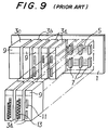
- Figure 9 a plurality of box-shaped control modules 3a, 3b and 3c are clustered into a group and are jointly mounted on a common support base plate 1.
- control modules 3a to 3c individually incorporate therein various electronic circuits not shown in the drawing, and serve as an input/output module 3a for input/output control or communication control of digital or analog signals, a main control module 3b including a CPU unit or the like for carrying out arithmetic processes, and a power source module 3c for converting AC utility power into a stabilized DC power, and supplying it to other control modules.
- control modules 3a to 3c are detachably mounted on a plurality of support connectors 7 which are in turn securely attached to the support base plate 1 and mutually connected by a composite signal line 5, and jointly form a control device such as a programmable controller.
- each of the control modules 3a to 3c is provided with a display unit 9 which lights up according to the operating condition of the corresponding control module, and the front faces of the input/output modules 3a are provided with connectors 11 and terminal bases 13 for connection with external equipment not shown in the drawing.
- control modules 3a to 3c normally prepare a number of different support base plates 1 having different arrangement of support connectors 7, and the buyer can choose a support base plate 1 corresponding to the number of control modules that suits the intended size of the system such as the programmable controller and the need of the buyer to expand or modify the size of the system.
- the manufacturer needs to prepare a number of different support base plates 1 having different numbers of support connectors 7 in advance to meet every possible need of the user, and this involves substantial cost and effort in manufacturing and stocking.
- each support base plate 1 can carry, and he has to purchase an additional support base plate 1 if he wishes to expand or otherwise modify the system.
- the conventional arrangement is not flexible enough to readily adapt itself to modification, and tends to require a high cost when a modification is effected.
- a primary object of the present invention is to provide a modular control device which can adapt itself to any size or complexity of the system, and allow its control modules to be readily changed without requiring any new support base plate having a different arrangement of connecting means such as support connectors.
- a second object of the present invention is to provide a modular control device which is so adaptable that the manufacturer is not required to produce a large number of different support base plates and stock all of them.
- a third object of the present invention is to provide a modular control device which is so adaptable that the user can modify an existing control device with a minimum cost.
- a fourth object of the present invention is to provide a modular control device which allows its control modules to be replaced both quickly and simply.
- a fifth object of the present invention is to provide a modular control device which can easily accommodate large control modules without requiring any special adapters.
- a control device comprising: a base member including a base circuit; base connectors arranged on the base member in association with the base circuit and directed to either lateral side thereof; and a module connector formed on the base member and electrically connected to the base circuit; a control module adapted to be mounted on the base member, and provided with a module circuit board adapted to be connected to the module connector; the base connectors being each adapted to be connected to an associated connector provided on an opposing lateral side of an adjacent base member.
- the base members may be individually and detachably mounted on a common mount such as a rail, and are adapted to be electrically and mechanically connected to adjacent base members.
- the module circuit board for each control module can be detachably mounted on any base member.
- a new control module can be added simply by adding a base member in addition to the new control module.
- An existing control module may be replaced with a new one simply by removing the existing control module from the base member and mounting the new control module on the same base member.
- the manufacturer is required to produce fewer kinds of components and can therefore benefit from the reduced cost in manufacturing and maintaining a stock.
- the user can benefit from the facility and the reduction in cost in expanding and otherwise modifying the control device.
- the casing is adapted to be detached from the base member without disconnecting the module circuit board from the module connector.
- the base circuit and the base connectors are mounted on a base circuit board which is detachably mounted on a base member main body, it is possible to standardize the base member main body, and modify the base circuit and/or connectors without increasing the cost in manufacturing and stocking the base members.
- the base connectors comprise connecting pins projecting from one lateral side of the base member, and connecting sockets for receiving connecting pins projecting laterally from an adjacent base member, a plurality of base members can be readily joined with one another simply by fitting the connecting pins into the associated connecting sockets.
- the control module comprises a casing which can be mounted on the base member and removably receive the module circuit board therein, and the casing is provided with notches for exposing the base connectors so that the provision of the casing would not interfere with the base connectors.
- a larger control module can be accommodated by assigning a plurality of base members for the large control module.
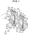
- FIG. 1 is an exploded perspective view of an essential part of an embodiment of the control device according to the present invention.
- This control device is constructed by combining a number of control modules which can carry out similar or different functions.
- each control module has certain standardized common features as described hereinafter, and the following description is in some places directed only to a single individual control module for the convenience of description.
- an electrically insulating base member 15 consists of an elongated planar member, and a U-shaped engagement piece 19 projects from an upper part of the vertically placed base member located between a pair of slots 17 cut into the base member 15 from its upper edge (refer to Figure 5).
- An engagement projection 21 projects from the engagement piece 19, and a pair of support pieces 23 extend along either side of the engagement piece 19 and the slots 17.
- An engagement piece 25 projects from a lower end portion of the base member 15, and the free end of this engagement piece 25 slightly projects upward into the shape of letter-L.
- the support pieces 23 and the engagement piece 25 can slide along the inner surfaces of a casing 27, and can fit into associated engagement holes 29 and 31 (31 is hidden in Figure 1) of the casing 27.
- An elongated base circuit board 33 is placed between the engagement pieces 19 and 25, and extends along the front surface of the base member 15, and is kept slightly spaced from the base member 15 by a pair of engagement columns 35 and 35 (the lower column is hidden in Figure 1).
- This base circuit board 33 carries a module connector 39 adapted to be connected to a module circuit board 37 received in the casing 27 as described hereinafter, and first and second base connectors 41 and 43 adapted to be electrically connected to the associated base connectors of the adjacent base members 15. These connectors 39 to 43 are electrically connected with one another via the base circuit board 33, and the first and second base connectors 41 and 43 form a part of a composite signal line 5 similar to the conventional composite signal line mentioned earlier.
- the first base connector 41 is placed on the vertically placed support member 15 via the base circuit board 33 in such a manner that the first base connector 41 is located on one lateral side of the base member 15, and the connecting pins 45 of the first base connector 41 project from the corresponding long side of the base member 15.
- the second base connector 43 is located on the other lateral side of the base member 15, and is provided with connecting sockets 47 adapted to receive the connecting pins 45 of the first base connector 41 of the adjacent base member 15.
- each of the base members 15 is integrally provided with a pair of engagement projections 49 projecting from upper and lower ends of one of the long sides of the base member 15 from which the connecting pins 45 project, and upper and lower ends of the opposing long side of the adjacent base member 15 are provided with engagement holes 51 adapted to receive the corresponding engagement projections 49 of the adjacent base member 15.
- Figure 3 shows only the lower engagement projection 49 and the lower engagement hole 51 of the base members 15, but the upper engagement projection 49 and the upper engagement hole 51 are also provided with similar structures.
- the base members 15 can be mechanically and firmly joined to one another by fitting the connecting pins 45 of the first base connector 41 of one of the base members 15 into the second base connector 43 of the adjacent base member 15, and engaging the engagement projections 49 with the associated engagement holes 51.
- the composite signal line 5 can be sequentially extended by the first and second base connectors 41 and 43.
- the base member 15 is provided with upper and lower engagement grooves 55 and 57 (refer to Figures 5 and 6) on a rear surface thereof adapted to engage a DIN rail 53 or the like, and can be adapted for easy attachment and detachment to and from the rail 53, for instance, by pulling a slide piece 59 downward against a biasing force.
- the slide piece 59 is vertically slidably supported and is urged upward by suitable spring means.
- numeral 61 denotes threaded holes for attaching the base member 15 to a support plate mounted on a wall which is not shown in the drawings.
- the casing 27 of the control module 63 fitted onto the base member 15 is made of plastic material molded into the shape of a box, and, as shown in Figures 5 to 7, is provided with an opening conforming to the outer profile of the base member 15, and a pair of notches 65 cut into the edges of either side of the opening in the shape of letter C in such a manner that the first and second base connectors 41 and 43 would not interfere with the casing 27 when it is fitted onto the base member 15, and appropriately expose the first and second base connectors 41 and 43.
- the material of the casing 27 is not limited to synthetic resin material, and may consist of other materials such as metal as long as it can be formed into the necessary shape.
- An engagement hole 29 is provided on a part of the upper surface of the casing 27 adjacent to the opening for engaging the engagement projection 21 of the engagement piece 19 of the base member 15, and an engagement hole 31 (refer to Figures 5 to 7) is provided in a part of the lower surface of the casing 27 adjacent to the opening in addition to a slide groove 67 for slidably receiving a free end of the engagement piece 25.
- the casing 27 accommodates therein a module circuit board 37 fitted therein through insertion grooves 69 extending from the opening, and a connector 71 is mounted on this module circuit board 37.
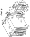
- This module circuit board 37 carries an electronic circuit for carrying out, for instance, the functions of an input/output unit 63a and a main control device 63b as shown in Figure 8.
- the module circuit board 37 is received in the casing 27 in such a manner that the module circuit board 37 occupies its position between the first and second base connectors 41 and 43 as indicated by one-dot chain lines of Figure 2, and comes into contact with connecting pieces of a terminal members (not shown in the drawings) extending from a terminal base 73 (refer to Figure 8) placed on the front face of the casing 27 as described hereinafter into the interior of the casing 27.
- module circuit board 37 is provided with a notch 77 as illustrated in Figure 7, it can be placed over the first and second base connectors 41 and 43 without interfering with them.
- the connector 71 is provided on one side of the module circuit board 37, and is provided with such a shape and placed at such a position that it will be connected to the module connector 39 when the casing 27 is fitted onto the base member 15.
- the module circuit board 37 is connected to the module connector 39 which is in turn connected to the circuit of the base circuit board 33.
- the circuit of the base circuit board 33 is connected to the adjacent base circuit boards 33 via the first and second base connectors 41 and 43.
- the structures formed between the engagement piece 19 and the engagement hole 29 and between the engagement piece 25 and the engagement hole 31 can be provided in both upper and lower parts, and their relationships can be reversed.
- the structure of the casing 27 of the control module 63 adapted to be mounted on the base member 15 can be freely determined.
- the front face may be provided with a terminal base 73 for external connection, an access hole 75 for operating an internal rotary switch, and connector holes 77 for communication purpose, as shown in Figure 8.
- control modules 63 input/output modules 63a, main control modules 63b, and power source modules are mounted on these base members 15.
- the system can be expanded by mounting an additional identical base member 15 on the rail 53, and fitting an additional control module 63 onto this additional base member 15. If desired, it is possible to modify the system by replacing the control module 63 with another using the same base member 15.
- the control device of the present invention is provided with a structure which may be summarized as given in the following.
- a module connector 39, and first and second base connectors 41 and 43 are mounted on a printed circuit board 33 which is in turn supported by a base member 15, and are arranged in such a manner that the connecting pins 45 of the first base connector 41 can be connected to the second base connector 43 of the adjacent base member 15.
- Engagement pieces 19 and 25 are provided on upper and lower ends of the base member 15, and the control module 63 incorporated with the module circuit board 37 is installed by engaging it with the engagement pieces 19 and 25, and the connector 71 of the module circuit board 37 is connected to the module connector 39. Therefore, the base member 15 can be used as a common component for different types of control modules 63, and clustering and separating the base members 15 are simplified. Furthermore, a desired control module 63 can be mounted on any one of the base members 15 at will.
- the manufacturer is not required to stock a number of different types of support base plates 1 for various possible needs of the user.
- the number of the control modules 63 that can be incorporated into the system is not limited, and the expansion and modification of the system can be accomplished in a simple manner.
- the base member 15 is provided with a first base connector 41 having connecting pins 45 projecting therefrom, and a second base connector 43 having connecting sockets 47 for receiving the connecting pins 45 of the first base connector 41, a plurality of base members 15 can be electrically connected with one another simply by fitting the connecting pins 45 of the first base connector 41 into the associated connecting sockets 47 of the second base connector 43 of the adjacent base member 15.
- the separation of the base members 15 can be equally readily effected simply by pulling the connecting pins 45 from the connecting sockets 47.
- the module circuit board 37 of the control module 63 is fitted into the casing 27 guided by insertion grooves 69 provided in the casing 27, and the connector 71 is connected to the module circuit board connector 39 of the base member 15, not only the base member 27 but also the casing 27 is adapted to be removed in a simple manner, and maintenance of the module circuit board 37 is simplified.
- the casing 27 of the control module 63 is provided with notches 65 on either side thereof, the first and second base connectors 41 and 43 are exposed from the side faces, and the connection and separation of the base member 15 can be accomplished in a simple manner.
- control device of the present invention it is possible to handle two or more of base members 15 as an individual base member when a control module 63 incorporated with a plurality of module circuit boards and assigned with a large number of functions is required to be installed, when a large number of input/output terminals are required to be provided on a single control module, or when the control module is commonly used by a number of different parts of the control system.
- control module 63 main control module 63b
- a casing 27 onto a double slot type base member 15 formed by combining two basic base members 15, and, alternatively, it is also possible to remove the individual circuit boards 33 of the connected base members 15, and replace it with a circuit of a double width although it is not shown in the drawings.
- control modules 63 which are often used in combination as a part of an overall structure of a control system, for instance a combination of a power source module and a CPU unit (a main control device). By doing so, it is possible to eliminate the first and second connectors, and this contributes to the reduction of cost.
- the first and second base connectors 41 and 43 are not necessarily required to be individually provided as long as the module circuit board connector 39 is electrically connected to the base connectors 41 and 43 via the base member 15 or the circuit board 33, and the base connectors 41 and 43 in turn connect the circuit boards 33 of adjacent base members 15 with each other.
- the connecting pins 45 of the base connectors 41 are not necessarily required to project laterally from the base member 15 as long as the base connectors 41 and 43 of adjacent circuit boards 33 can be connected with each other.
- the structure of the connectors themselves can be also freely determined.
- circuit board 33 it is not essential to arrange the circuit board 33 on the base member 15, and the circuit board 33 can be eliminated by appropriately arranging and connecting the module base connector 39 and the base connectors 41 and 43.
- control modules were arranged laterally, but may also be arranged vertically or one over the other.
- adjacent base members can be separably connected to each other via base connectors, and the base members can be standardized for various kinds of control modules.
- the base members can be standardized for various kinds of control modules.
- a number of control modules can be joined and separated at will, and the internal module circuit board of each control module can be detachably mounted on the base member.
- the manufacturer benefits from the improved handling of the control modules and base members, and the simplified stock management, and the user benefits from the possibility of readily combining and separating standardized common base members, the facility of expansion and modification of the system, and the resulting reduction in cost.
- connection and separation of a plurality of base members is further facilitated.
- control module By forming the control module with a module circuit board detachably fitted in the casing, maintenance work is simplified without impairing the facility in detaching the module circuit board which has been an advantage of the conventional support base plate structure.
- the base members can be used without modification even when the size of the control module is increased.
- the base members can be standardized without regard to the size of the control module.
Applications Claiming Priority (2)
| Application Number | Priority Date | Filing Date | Title |
|---|---|---|---|
| JP351519/93 | 1993-12-28 | ||
| JP35151993 | 1993-12-28 |
Publications (1)
| Publication Number | Publication Date |
|---|---|
| EP0661915A1 true EP0661915A1 (de) | 1995-07-05 |
Family
ID=18417839
Family Applications (1)
| Application Number | Title | Priority Date | Filing Date |
|---|---|---|---|
| EP94120797A Withdrawn EP0661915A1 (de) | 1993-12-28 | 1994-12-28 | Modular-Steuersystem |
Country Status (1)
| Country | Link |
|---|---|
| EP (1) | EP0661915A1 (de) |
Cited By (30)
| Publication number | Priority date | Publication date | Assignee | Title |
|---|---|---|---|---|
| WO1998018266A2 (de) * | 1996-10-17 | 1998-04-30 | Robert Bosch Gmbh | Fernmeldevermittlungsanlage |
| DE19651962A1 (de) * | 1996-12-13 | 1998-06-18 | Siemens Ag | Kaskadierbares Kontaktsystem mit Unterbrechungs- und Einspeisemöglichkeit an jedem Kontaktelement |
| EP0896504A2 (de) * | 1997-08-05 | 1999-02-10 | PHOENIX CONTACT GmbH & Co. | Elektrisches oder elektronisches Gerät |
| DE19748531A1 (de) * | 1997-11-03 | 1999-05-06 | Siemens Ag | Aufbausystem für Verbraucherabzweige mit stehender Verdrahtung |
| EP0914029A2 (de) * | 1997-11-03 | 1999-05-06 | Siemens Aktiengesellschaft | Modulares Automatisierungsgerät und Baugruppe eines modularen Automatisierungsgerätes |
| DE19807710A1 (de) * | 1998-02-24 | 1999-09-09 | Siemens Ag | Modulares Automatisierungsgerät und Baugruppe eines modularen Automatisierungsgerätes |
| DE19816170A1 (de) * | 1998-04-09 | 1999-10-21 | Sew Eurodrive Gmbh & Co | Steuerungsmodul |
| WO2000025560A1 (en) * | 1998-10-22 | 2000-05-04 | Parker Hannifin Plc | Automation control module and base for mounting thereon |
| US6241561B1 (en) | 1999-01-25 | 2001-06-05 | Weidmuller Interface Gmbh & Co. | Terminal block arrangement for an electrical system |
| EP1239544A2 (de) * | 2001-03-07 | 2002-09-11 | Weidmüller Interface GmbH & Co. | Elektrisches Gerät mit Busleiterabschnitt |
| EP1365478A1 (de) * | 2002-05-21 | 2003-11-26 | Weidmüller Interface GmbH & Co. | Modulreihung und Adaptermodul |
| WO2004075357A1 (en) * | 2003-02-20 | 2004-09-02 | Rockwell Automation Technologies, Inc. | Modular electrical device with improved seal |
| WO2004075356A1 (en) * | 2003-02-20 | 2004-09-02 | Rockwell Automation Technologies, Inc. | Modular electrical device |
| US6881101B2 (en) | 2003-02-20 | 2005-04-19 | Rockwell Automation Technologies, Inc. | Modular electrical device |
| DE102005032730B4 (de) * | 2005-07-13 | 2008-01-24 | Siemens Ag | Anordnung mit einem Träger zur Aufnahme und Halterung einer Baugruppe eines Automatisierungsgerätes |
| DE102007006830A1 (de) * | 2007-02-07 | 2008-08-14 | Phoenix Contact Gmbh & Co. Kg | Steuer- und/oder Datenübertragungsmodul |
| WO2011141314A1 (de) * | 2010-05-10 | 2011-11-17 | Weidmüller Interface GmbH & Co. KG | Tragschienenbussystem |
| DE102011001069A1 (de) | 2011-03-03 | 2012-09-06 | Harting Electric Gmbh & Co. Kg | System von Steckverbindern |
| WO2014063821A1 (de) * | 2012-10-25 | 2014-05-01 | Friedrich Lütze GmbH | Gehäuse für an einer tragschiene anbringbare und aneinander anreihbare vorrichtungen, zugehöriges gehäuse-baukastensystem und vorrichtung mit einem solchen gehäuse |
| EP2506692A3 (de) * | 2011-03-23 | 2015-02-18 | Phoenix Contact GmbH & Co. KG | Din-Schienen-Montagebasis für ein feldbusredundantes Stromversorgungsgerät |
| US8961201B2 (en) | 2010-05-10 | 2015-02-24 | Weidmueller Interface Gmbh & Co. Kg | Mounting rail bus system |
| DE102013112117A1 (de) * | 2013-11-04 | 2015-05-07 | Phoenix Contact Gmbh & Co. Kg | Funktionskomponente für ein Komponentenaufbausystem |
| EP3261419A3 (de) * | 2016-06-22 | 2018-02-28 | Honeywell International Inc. | Verfahren für hardwaremigration zum austauschen von steuergeräten |
| WO2018109124A1 (de) * | 2016-12-16 | 2018-06-21 | Phoenix Contact Gmbh & Co Kg | Anordnung von tragelementen elektronischer module |
| DE102018133647A1 (de) * | 2018-12-28 | 2020-07-02 | Beckhoff Automation Gmbh | Schaltschranksystem aus Basismodul und Funktionsmodulen sowie Funktionsmodul |
| DE102008058090B4 (de) | 2008-11-18 | 2021-08-26 | Abb Ag | Ein-/Ausgabemodul für ein Automatisierungsgerät |
| WO2022178602A1 (pt) * | 2021-02-26 | 2022-09-01 | Novus Produtos Eletrônicos Ltda | Controlador de processos industriais e método de detecção automática de módulos de expansão acoplado em dito controlador de processos |
| US11533820B2 (en) | 2018-12-28 | 2022-12-20 | Beckhoff Automation Gmbh | Base module and functional module for a control-cabinet system |
| US11540413B2 (en) | 2018-12-28 | 2022-12-27 | Beckhoff Automation Gmbh | Base module and functional module for a switch-cabinet system, and switch-cabinet system |
| US11956915B2 (en) | 2019-03-11 | 2024-04-09 | Beckhoff Automation Gmbh | Switch-cabinet system with sealing insert |
Citations (4)
| Publication number | Priority date | Publication date | Assignee | Title |
|---|---|---|---|---|
| DE2810071A1 (de) * | 1978-03-08 | 1979-09-13 | Siemens Ag | Anordnung zum befestigen und verdrahten von elektrischen geraeten |
| DE3603750A1 (de) * | 1986-02-06 | 1987-08-13 | Siemens Ag | Automatisierungsgeraet |
| US4790762A (en) * | 1985-07-23 | 1988-12-13 | Honeywell Inc. | Backplane for a modularly expandable programmable controller |
| WO1992022997A1 (de) * | 1991-06-11 | 1992-12-23 | Erwin Bernecker | Aus einzelnen baugruppen bestehende elektrische anlage |
-
1994
- 1994-12-28 EP EP94120797A patent/EP0661915A1/de not_active Withdrawn
Patent Citations (4)
| Publication number | Priority date | Publication date | Assignee | Title |
|---|---|---|---|---|
| DE2810071A1 (de) * | 1978-03-08 | 1979-09-13 | Siemens Ag | Anordnung zum befestigen und verdrahten von elektrischen geraeten |
| US4790762A (en) * | 1985-07-23 | 1988-12-13 | Honeywell Inc. | Backplane for a modularly expandable programmable controller |
| DE3603750A1 (de) * | 1986-02-06 | 1987-08-13 | Siemens Ag | Automatisierungsgeraet |
| WO1992022997A1 (de) * | 1991-06-11 | 1992-12-23 | Erwin Bernecker | Aus einzelnen baugruppen bestehende elektrische anlage |
Cited By (51)
| Publication number | Priority date | Publication date | Assignee | Title |
|---|---|---|---|---|
| WO1998018266A3 (de) * | 1996-10-17 | 1998-08-06 | Bosch Gmbh Robert | Fernmeldevermittlungsanlage |
| WO1998018266A2 (de) * | 1996-10-17 | 1998-04-30 | Robert Bosch Gmbh | Fernmeldevermittlungsanlage |
| DE19651962A1 (de) * | 1996-12-13 | 1998-06-18 | Siemens Ag | Kaskadierbares Kontaktsystem mit Unterbrechungs- und Einspeisemöglichkeit an jedem Kontaktelement |
| EP0896504A2 (de) * | 1997-08-05 | 1999-02-10 | PHOENIX CONTACT GmbH & Co. | Elektrisches oder elektronisches Gerät |
| EP0896504A3 (de) * | 1997-08-05 | 1999-09-08 | PHOENIX CONTACT GmbH & Co. | Elektrisches oder elektronisches Gerät |
| EP0914029A3 (de) * | 1997-11-03 | 1999-10-27 | Siemens Aktiengesellschaft | Modulares Automatisierungsgerät und Baugruppe eines modularen Automatisierungsgerätes |
| DE19748531A1 (de) * | 1997-11-03 | 1999-05-06 | Siemens Ag | Aufbausystem für Verbraucherabzweige mit stehender Verdrahtung |
| EP0914029A2 (de) * | 1997-11-03 | 1999-05-06 | Siemens Aktiengesellschaft | Modulares Automatisierungsgerät und Baugruppe eines modularen Automatisierungsgerätes |
| US6452785B1 (en) | 1997-11-03 | 2002-09-17 | Siemens Ag | Construction system for load feeders with permanent wiring |
| DE19807710C2 (de) * | 1998-02-24 | 2002-07-18 | Siemens Ag | Modulares Automatisierungsgerät und Baugruppe eines modularen Automatisierungsgerätes |
| DE19807710A1 (de) * | 1998-02-24 | 1999-09-09 | Siemens Ag | Modulares Automatisierungsgerät und Baugruppe eines modularen Automatisierungsgerätes |
| DE19816170C5 (de) * | 1998-04-09 | 2004-09-23 | Sew-Eurodrive Gmbh & Co | Steuerungsmodul |
| DE19816170A1 (de) * | 1998-04-09 | 1999-10-21 | Sew Eurodrive Gmbh & Co | Steuerungsmodul |
| DE19816170C2 (de) * | 1998-04-09 | 2002-10-31 | Sew Eurodrive Gmbh & Co | Steuerungsmodul |
| WO2000025560A1 (en) * | 1998-10-22 | 2000-05-04 | Parker Hannifin Plc | Automation control module and base for mounting thereon |
| US6241561B1 (en) | 1999-01-25 | 2001-06-05 | Weidmuller Interface Gmbh & Co. | Terminal block arrangement for an electrical system |
| EP1239544A2 (de) * | 2001-03-07 | 2002-09-11 | Weidmüller Interface GmbH & Co. | Elektrisches Gerät mit Busleiterabschnitt |
| EP1239544A3 (de) * | 2001-03-07 | 2005-08-10 | Weidmüller Interface GmbH & Co. | Elektrisches Gerät mit Busleiterabschnitt |
| EP1365478A1 (de) * | 2002-05-21 | 2003-11-26 | Weidmüller Interface GmbH & Co. | Modulreihung und Adaptermodul |
| WO2004075357A1 (en) * | 2003-02-20 | 2004-09-02 | Rockwell Automation Technologies, Inc. | Modular electrical device with improved seal |
| WO2004075356A1 (en) * | 2003-02-20 | 2004-09-02 | Rockwell Automation Technologies, Inc. | Modular electrical device |
| US6881101B2 (en) | 2003-02-20 | 2005-04-19 | Rockwell Automation Technologies, Inc. | Modular electrical device |
| US6916194B2 (en) | 2003-02-20 | 2005-07-12 | Rockwell Automation Technologies, Inc. | Modular electrical device with improved seal |
| US7021974B2 (en) | 2003-02-20 | 2006-04-04 | Rockwell Automation Technologies, Inc. | Modular electrical device |
| DE102005032730B4 (de) * | 2005-07-13 | 2008-01-24 | Siemens Ag | Anordnung mit einem Träger zur Aufnahme und Halterung einer Baugruppe eines Automatisierungsgerätes |
| DE102007006830A1 (de) * | 2007-02-07 | 2008-08-14 | Phoenix Contact Gmbh & Co. Kg | Steuer- und/oder Datenübertragungsmodul |
| DE102007006830B4 (de) * | 2007-02-07 | 2009-01-08 | Phoenix Contact Gmbh & Co. Kg | Steuer- und/oder Datenübertragungsmodul |
| DE102007006830B8 (de) * | 2007-02-07 | 2009-12-24 | Phoenix Contact Gmbh & Co. Kg | Steuer- und/oder Datenübertragungsmodul |
| US8209455B2 (en) | 2007-02-07 | 2012-06-26 | Phoenix Contact Gmbh & Co. Kg | Control and/or data-transmission module |
| DE102008058090B4 (de) | 2008-11-18 | 2021-08-26 | Abb Ag | Ein-/Ausgabemodul für ein Automatisierungsgerät |
| WO2011141314A1 (de) * | 2010-05-10 | 2011-11-17 | Weidmüller Interface GmbH & Co. KG | Tragschienenbussystem |
| US8961201B2 (en) | 2010-05-10 | 2015-02-24 | Weidmueller Interface Gmbh & Co. Kg | Mounting rail bus system |
| DE102011001069A1 (de) | 2011-03-03 | 2012-09-06 | Harting Electric Gmbh & Co. Kg | System von Steckverbindern |
| DE102011001069B4 (de) | 2011-03-03 | 2018-03-22 | Harting Electric Gmbh & Co. Kg | Verfahren zum Verriegeln eines ersten Systems von Steckverbindern mit einem zweiten System von Steckverbindern |
| EP2506692A3 (de) * | 2011-03-23 | 2015-02-18 | Phoenix Contact GmbH & Co. KG | Din-Schienen-Montagebasis für ein feldbusredundantes Stromversorgungsgerät |
| WO2014063821A1 (de) * | 2012-10-25 | 2014-05-01 | Friedrich Lütze GmbH | Gehäuse für an einer tragschiene anbringbare und aneinander anreihbare vorrichtungen, zugehöriges gehäuse-baukastensystem und vorrichtung mit einem solchen gehäuse |
| US9795046B2 (en) | 2013-11-04 | 2017-10-17 | Phoenix Contact Gmbh & Co Kg | Device for securing a functional component to a support rail |
| CN105746007A (zh) * | 2013-11-04 | 2016-07-06 | 菲尼克斯电气公司 | 部件构建系统的功能部件 |
| DE102013112117A1 (de) * | 2013-11-04 | 2015-05-07 | Phoenix Contact Gmbh & Co. Kg | Funktionskomponente für ein Komponentenaufbausystem |
| CN105746007B (zh) * | 2013-11-04 | 2018-09-25 | 菲尼克斯电气公司 | 部件构建系统的功能部件 |
| EP3261419A3 (de) * | 2016-06-22 | 2018-02-28 | Honeywell International Inc. | Verfahren für hardwaremigration zum austauschen von steuergeräten |
| US10412849B2 (en) | 2016-06-22 | 2019-09-10 | Honeywell International Inc. | Hardware migration |
| US10806047B2 (en) | 2016-12-16 | 2020-10-13 | Phoenix Contact Gmbh & Co. Kg | Arrangement of support elements of electronic modules |
| WO2018109124A1 (de) * | 2016-12-16 | 2018-06-21 | Phoenix Contact Gmbh & Co Kg | Anordnung von tragelementen elektronischer module |
| DE102018133647A1 (de) * | 2018-12-28 | 2020-07-02 | Beckhoff Automation Gmbh | Schaltschranksystem aus Basismodul und Funktionsmodulen sowie Funktionsmodul |
| US11490538B2 (en) | 2018-12-28 | 2022-11-01 | Beckhoff Automation Gmbh | Control-cabinet system with base module and functional module, as well as functional module |
| US11533820B2 (en) | 2018-12-28 | 2022-12-20 | Beckhoff Automation Gmbh | Base module and functional module for a control-cabinet system |
| US11540413B2 (en) | 2018-12-28 | 2022-12-27 | Beckhoff Automation Gmbh | Base module and functional module for a switch-cabinet system, and switch-cabinet system |
| EP3884741B1 (de) * | 2018-12-28 | 2023-10-04 | Beckhoff Automation GmbH | Schaltschranksystem aus basismodul und funktionsmodulen sowie funktionsmodul |
| US11956915B2 (en) | 2019-03-11 | 2024-04-09 | Beckhoff Automation Gmbh | Switch-cabinet system with sealing insert |
| WO2022178602A1 (pt) * | 2021-02-26 | 2022-09-01 | Novus Produtos Eletrônicos Ltda | Controlador de processos industriais e método de detecção automática de módulos de expansão acoplado em dito controlador de processos |
Similar Documents
| Publication | Publication Date | Title |
|---|---|---|
| EP0661915A1 (de) | Modular-Steuersystem | |
| US5099391A (en) | Housing for a rack mountable power supply for use with a programmable logic controller | |
| US5612854A (en) | Computer power supply apparatus | |
| US5940274A (en) | Casing for computer and computer employing the same casing with removable rear cable cover | |
| US6717053B2 (en) | Work surface power module system with interchangeable covers | |
| CN100568429C (zh) | 电气设备中的端子装置 | |
| EP0726699A1 (de) | Modular elektronisches Gerät | |
| US4251853A (en) | Annunciator of modular construction | |
| US4519667A (en) | Electrical connector | |
| EP0120163B1 (de) | Wechselstromleistungseingangsmodul | |
| JPH07200011A (ja) | 制御装置 | |
| JPH0588726A (ja) | 自動化装置 | |
| US7675739B2 (en) | Fuse module with removable fuse carrier for fused electrical device | |
| US5032951A (en) | Module for a control system comprising several modules juxtaposed on a carrier | |
| EP0508059B1 (de) | Sicherungshaltergehäuse modularer Struktur | |
| EP0152743A1 (de) | Modularer elekrischer Steckverbinder | |
| US5214621A (en) | Universal circuit board housing with a hinged member | |
| CA1069207A (en) | Quick disconnect card-on-board electronic package assembly | |
| US5460541A (en) | Jack socket assembly | |
| JP3925089B2 (ja) | 電源装置ならびに電源ユニットの連結構造 | |
| JP2794965B2 (ja) | 制御装置のベースユニット | |
| EP0145380A2 (de) | Elektrische Vorrichtung, die auf einer Oberfläche oder in einem Paneel montiert werden kann | |
| DE102004056363B4 (de) | Flexibles erweiterbares Automatisierungsgerät | |
| US20220287192A1 (en) | A modular and configurable electrical device group | |
| US4468718A (en) | Enclosure and mounting member for printed circuit boards |
Legal Events
| Date | Code | Title | Description |
|---|---|---|---|
| PUAI | Public reference made under article 153(3) epc to a published international application that has entered the european phase |
Free format text: ORIGINAL CODE: 0009012 |
|
| AK | Designated contracting states |
Kind code of ref document: A1 Designated state(s): DE FR GB IT |
|
| STAA | Information on the status of an ep patent application or granted ep patent |
Free format text: STATUS: THE APPLICATION IS DEEMED TO BE WITHDRAWN |
|
| 18D | Application deemed to be withdrawn |
Effective date: 19951206 |