EP1022897B1 - Bildverarbeitung und Farbumwandlung - Google Patents
Bildverarbeitung und Farbumwandlung Download PDFInfo
- Publication number
- EP1022897B1 EP1022897B1 EP00300302A EP00300302A EP1022897B1 EP 1022897 B1 EP1022897 B1 EP 1022897B1 EP 00300302 A EP00300302 A EP 00300302A EP 00300302 A EP00300302 A EP 00300302A EP 1022897 B1 EP1022897 B1 EP 1022897B1
- Authority
- EP
- European Patent Office
- Prior art keywords
- color gamut
- color
- output device
- image
- gamut
- Prior art date
- Legal status (The legal status is an assumption and is not a legal conclusion. Google has not performed a legal analysis and makes no representation as to the accuracy of the status listed.)
- Expired - Lifetime
Links
- 238000006243 chemical reaction Methods 0.000 title claims description 66
- 238000012545 processing Methods 0.000 title description 11
- 238000000034 method Methods 0.000 claims description 48
- 230000006870 function Effects 0.000 claims description 43
- 239000003086 colorant Substances 0.000 claims description 17
- 230000008859 change Effects 0.000 claims description 15
- 238000003672 processing method Methods 0.000 claims description 2
- 230000000063 preceeding effect Effects 0.000 claims 1
- 230000009467 reduction Effects 0.000 description 155
- 238000011156 evaluation Methods 0.000 description 17
- 238000013507 mapping Methods 0.000 description 12
- 230000000007 visual effect Effects 0.000 description 8
- 230000035807 sensation Effects 0.000 description 7
- 238000005452 bending Methods 0.000 description 5
- 230000001419 dependent effect Effects 0.000 description 4
- 239000000976 ink Substances 0.000 description 4
- 230000004456 color vision Effects 0.000 description 3
- 230000000694 effects Effects 0.000 description 3
- 238000012886 linear function Methods 0.000 description 2
- 230000008447 perception Effects 0.000 description 2
- 230000008569 process Effects 0.000 description 2
- 239000000654 additive Substances 0.000 description 1
- 230000000996 additive effect Effects 0.000 description 1
- 230000004888 barrier function Effects 0.000 description 1
- 238000004364 calculation method Methods 0.000 description 1
- 230000009189 diving Effects 0.000 description 1
- 238000003384 imaging method Methods 0.000 description 1
- 238000011835 investigation Methods 0.000 description 1
- 238000005259 measurement Methods 0.000 description 1
- 239000000203 mixture Substances 0.000 description 1
- 238000012546 transfer Methods 0.000 description 1
- 230000009466 transformation Effects 0.000 description 1
Images


Classifications
-
- H—ELECTRICITY
- H04—ELECTRIC COMMUNICATION TECHNIQUE
- H04N—PICTORIAL COMMUNICATION, e.g. TELEVISION
- H04N1/00—Scanning, transmission or reproduction of documents or the like, e.g. facsimile transmission; Details thereof
- H04N1/46—Colour picture communication systems
- H04N1/56—Processing of colour picture signals
- H04N1/60—Colour correction or control
- H04N1/6058—Reduction of colour to a range of reproducible colours, e.g. to ink- reproducible colour gamut
-
- G—PHYSICS
- G09—EDUCATION; CRYPTOGRAPHY; DISPLAY; ADVERTISING; SEALS
- G09G—ARRANGEMENTS OR CIRCUITS FOR CONTROL OF INDICATING DEVICES USING STATIC MEANS TO PRESENT VARIABLE INFORMATION
- G09G5/00—Control arrangements or circuits for visual indicators common to cathode-ray tube indicators and other visual indicators
- G09G5/02—Control arrangements or circuits for visual indicators common to cathode-ray tube indicators and other visual indicators characterised by the way in which colour is displayed
- G09G5/06—Control arrangements or circuits for visual indicators common to cathode-ray tube indicators and other visual indicators characterised by the way in which colour is displayed using colour palettes, e.g. look-up tables
Definitions
- the present invention relates to an image processing apparatus and method for reducing, when the color gamut of an output device is different from that of an input device, the color gamut of a color signal outside the output device color gamut to provide a color near to that in the input device. Also, the present invention relates to a color gamut conversion creating apparatus and method for creating a color gamut conversion table for use to reduce a color gamut. Also, the present invention relates to a recording medium having recorded therein an image processing program in accordance with which a color gamut is reduced. Also, the present invention relates to a recording medium having recorded therein a color gamut conversion table creating program in accordance with which a color gamut conversion table for use to reduce a color gamut is created.
- color management system As various systems dealing with color images have become popular, it has been demanded to attain a so-called device-independent color concept intended to reproduce a color image in the same colors at different types of devices included in the systems.
- the system to implement the device-independent color is generally called "color management system".
- color management system As typical examples of this color management system, there are already available Colorsync included in Mac OS, ICM in Windows 98 and the like.
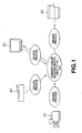
- FIG. 1 there is schematically illustrated the concept of the color management system in which physical colorimetric values of color signals in input and output devices are combined to implement a device-independent color. More particularly, as shown in FIG. 1, a color signal from an input device (such as video camera 61, scanner 62, monitor 63 or the like) is converted to a color signal in a device-independent color space (CIE/XYZ, CIE/L*a*b* or the like) on the basis of a device profile in which a color gamut conversion formula or color gamut conversion table is defined for each of the input devices.
- a color signal from an input device such as video camera 61, scanner 62, monitor 63 or the like
- CIE/XYZ, CIE/L*a*b* color gamut conversion formula or color gamut conversion table
- an output device (monitor 63, printer 64 or the like) to output the color signal
- the latter is converted to a color signal in a color space corresponding to the device on the basis of a device profile in which a color gamut conversion formula or color gamut conversion table is defined for each of the output devices.
- a device-independent color is implemented by converting once the input device color signal to a color signal in a device-independent color space on the basis of a device profile.
- the "device profile” is a file in which a color gamut conversion formula or color gamut conversion table is defined. In other words, it is a file having stored therein a group of parameters calculated from relations between device color signals (RGB, CMYK or the like) and chromatic values (XYZ, L*a*b* or the like) measured by a colorimeter or the like.
- the CRT monitor reproduces a color by additive mixture of three color stimuli, namely, red (R), green (G) and blue (B), emitted from their respective phosphors on a face plate.
- the color gamut of the CRT monitor depends upon the types of the phosphors used on the face plate.
- the printer uses three color inks, namely, cyan (C), magenta (M) and yellow (Y) (or four color inks including black (K) in addition to the three color inks) to reproduce a color. That is, the color gamut of the printer depends upon the types of inks used therein. Further, the printer color gamut varies depending upon the type of a paper as an image recording medium, the gradation reproducing method, etc.
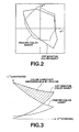
- FIG. 2 shows a typical color gamut of CRT monitor and a typical color gamut of printer, integrated in the direction of L* and plotted in a plane a*-b*.
- the CRT monitor and printer color gamuts are different from each other as shown in FIG. 2.
- the color gamut of the printer color is generally smaller than that of the CRT monitor, and especially in the green and blue color gamuts, the printer color gamut is extremely smaller than the CRT monitor color gamut.
- FIG. 3 shows the typical color gamut of CRT monitor and that of printer, plotted in a plane C*-L*.
- the output device color gamut is smaller than the input device color gamut as in the above, the output device cannot reproduce all colors at the input device and the colors have to be processed in such a manner that they fall within the output device color gamut.
- all the colors have to be processed to fall within the output device color gamut while image information (gradation, tint, etc.) presented at the input device are being maintained.
- This process is generally called "color gamut reduction".
- printers are rather narrower in color gamut than other devices. So, for a printer to print out an, the color reproducibility often depends upon which color gamut reduction technique is employed.
- a color gamut is reduced in a common color space independent of any device, especially in a color space suitable for human visual sensation (for example, CIE/L*C*h color space). More particularly, a color gamut may be reduced after an input color signal is converted to a device-independent color signal as shown in FIG. 4. Otherwise, as shown in FIG. 5, when a device profile is created, a color gamut conversion formula or a color gamut conversion table may be defined taking also a color gamut reduction in consideration, and a color gamut reduction may be effected simultaneously with converting a color signal on the basis of the device profile.
- the human color vision has three attributes including a lightness, chroma and hue.
- the color gamut reduction is effected in a color space based on these three attributes of the human color vision.
- the color space includes, for example, a CIE/L*C*h color space.
- the L*C*h is a polar coordinate to which L*a*b* and L*u*v* are converted.
- the L* indicates a lightness
- C* indicates a chroma
- h indicates a hue.
- the techniques of color gamut reduction effected in such a color space are generally classified into three kinds: one-, two- and three-dimensional color gamut reductions.
- the Applicant of the present invention has disclosed in the Japanese Unexamined Patent Application Publication No.. 10-84487 a method of color gamut reduction in which each of three terms (lightness difference, chroma difference and hue difference) in a color difference formula is weighted (with a reduction factor) and the color gamut is reduced in the direction of a minimum color difference.
- ⁇ E ⁇ L * 2 + ⁇ C * 2 + ⁇ H * 2 1 / 2
- ⁇ L*, ⁇ C* and ⁇ H* are differences in lightness, chroma and hue, respectively, between two colors.
- FIG. 9 shows an area where the color difference ⁇ E given by the equation (1-9) is constant (this area will be referred to as "constant color difference area” hereinafter), plotted for some typical points in a plane a*-b*.
- the difference between a color indicated with a mark "X” and a color plotted along a circle enclosing the mark "X”, namely, the color difference ⁇ E given by the equation (1-9) will be constant at all points along the circle.
- the constant color difference area plotted in the plane a*-b* is indicated with the circle in FIG. 9, when the color difference area is considered three-dimensionally (a lightness L* is also included), it will be given as a spatial sphere.
- FIG. 10 shows that the color gamut reducing direction is changed by changing the reduction factor additionally put in the color difference formula.
- the color gamut reduction will be closer to the one-dimensional one.
- the color gamut reduction will be closer to the two-dimensional one.
- the reduction factor K l is increased, the reduction ratio will be larger in the direction of lightness.
- the reduction factor K c is larger, the reduction ratio will be larger in the direction of chroma.
- the reduction factors K l and K c are made larger, mainly the lightness and chroma will be reduced while the hue is not so much changed. Namely, the color gamut reduction will be closer to the two dimensional one.
- the reduction factors K l , K c and K h are set to all one, the color difference will be equal to a one given by the equation (1-9).
- FIG. 11 shows an example of the change of the constant color difference area in relation to the change of the reduction factor
- FIG. 12 shows another example of the change of the constant color difference area in relation to the change of the reduction factor.
- FIG. 11 shows a change of the constant color difference area when the reduction factor K c is increased.
- a dotted-line circle indicates a constant color difference area given by the color difference formula represented by the equation (1-9)
- a solid-line ellipse indicates a constant color difference area given by the color difference formula represented by the equation (1-10) in which the reduction factor K c is increased.
- FIG. 12 shows a change of the constant color difference area when the reduction factor K h is increased.
- FIG. 11 shows an example of the change of the constant color difference area in relation to the change of the reduction factor
- FIG. 12 shows another example of the change of the constant color difference area in relation to the change of the reduction factor.
- FIG. 11 shows a change of the constant color difference area when the reduction factor K c is increased.
- a dotted-line circle indicates a constant color difference area given by the color difference formula represented by the equation (1-9)
- a solid-line ellipse indicates a constant color difference area given by the color difference formula represented by the equation (1-10) in which the reduction factor K h is increased.
- the color gamut is reduced with the hue kept constant.
- the color gamut has to be reduced more in the direction of lightness or chroma.
- the reduction of the color gamut of an image in the direction of lightness will reduce the contrast of the image, the more reduction of the color gamut in the direction of lightness will cause the whole image to lose a third dimension.
- the reduction of the color gamut in the direction of chroma will lower the definition of the image. So, if the color gamut is reduced more in the direction of chroma will cause the image to give a reduced impact.
- the one- or two-dimensional color gamut reduction is applied to an image created by the computer graphic, namely, an image having an extremely high chroma and a third dimension, these features of the image will be lost to a considerable extent.
- the reduction ratio in the directions of lightness and chroma should be small while the hue is changed to some extent. This can be attained by the three-dimensional color gamut reduction.
- the three-dimensional color gamut reduction is also disadvantageous in that a certain color will be changed too much in the direction of hue. This phenomenon will remarkably take place in the blue area. If the three-dimensional color gamut reduction is applied to an image including a blue area, the image will have only the blue area thereof appearing reddish. Note that this phenomenon will be a problem also in the one- and two-dimensional color gamut reductions as the case may be.
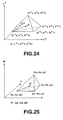
- FIG. 13 shows a data prepared in the Munsell V3, plotted in the CIE/L*a*b* color space.
- the Munsell data was prepared on the basis of the human visual sensation, so that a Munsell data should be able to be linearly plotted radially in a color space which is based on the human visual sensation.
- the locus delineated by points derived from plotting of the Munsell data is a curve, from which it is known that in the CIE/L*a*b* color space, the hue line of the blue area is considerably bent.
- the color gamut has to be reduced with the bending of the hue line taken in consideration.
- the color difference formula is defined as given by the following equations (2-1) and (2-2), and the color gamut reduction is made in the direction of a minimum color difference ⁇ E given by the equation (2-1) or (2-2).
- K l , K c , K h , K ll , K lc , K lh , K cl , K cc , K ch , K hl , K hc and K hh are predetermined constants, respectively, or functions of a lightness L*, chroma C* and hue h
- the constant color difference area can freely be changed correspondingly to the hue or the like. This is shown in FIGS. 14 to 17.
- a dotted-line ellipse indicates an example of the constant color difference area for which the color difference formula is defined as given by the equation (1-10).
- a solid-line ellipse indicates an example of the constant color difference area of which the direction is changed by putting a term ( ⁇ L*, ⁇ C*) in the color difference formula.
- a solid-line ellipse indicates an example of the constant color difference area of which the direction is changed by putting a term ⁇ C*, ⁇ H*) in the color difference formula.
- a solid-line ellipse indicates an example of the constant color difference area of which the direction is changed by defining K ch as functions of the chroma C* and hue h .
- the constant color difference area can be directed towards the directions of lightness L* and chroma C* while the hue h is kept constant.
- K lc as a function of the lightness L*, it is also made possible to change an area having a high lightness L* in the direction of a lower lightness and an area having a low lightness L* in the direction of a higher lightness, as shown in FIG. 14.
- the constant color difference area can also be directed towards a point as shown in FIG. 15, for example.
- the color gamut can be reduced in the direction of a certain point even when the three-dimensional color gamut reduction is adopted.
- the direction towards the achromatic axis of the constant color difference area can also be changed to another direction as shown in FIG. 16.
- the putting of the term ( ⁇ C* ⁇ H*) in the color difference formula is a very effective means for compensation of the bending of the hue line.
- K ch as a function of the hue h , it is also made possible to change the amount of compensation of the bending of the hue line for each hue.
- K ch as a function of the hue h to provide a larger amount of compensation for an area such as the blue area in which the hue line is much bent while providing a small amount of compensation for an area in which the hue line is not much bent, the color gamut can be reduced correspondingly to a bending of the hue line.
- K ch as functions of the chroma C* and hue h
- the color difference formula can also be defined for the constant color difference area to extent along the bent hue line as shown in FIG. 17. This is very effective for compensation of the blue area in the color gamut reduction.
- K ch as functions of chroma C* and hue h , it is made possible to solve the problem that when a color gamut is reduced, the direction of the constant color difference area is changed excessively in the direction of the hue in the blue area.
- an image processor as claimed in claim 1.
- the color gamut conversion table creating method will be described concerning a color gamut conversion table for use to convert a color signal between a color signal in a device-independent color space (will be referred to as "chromatic signal” hereinafter) and a color signal in a device-dependent color space (will be referred to as “device signal” hereinafter), by way of example.
- chromatic signal a color signal in a device-independent color space
- device signal a color signal in a device-dependent color space
- the color gamut conversion table is a table stored in a device profile set for each device to implement a device-independent color. It is also called "lookup table”.
- the device is a one which reproduces a color in C (cyan), M (magenta) and Y (yellow), such as a color printer or the like. Therefore, the device signal is a CMY signal corresponding to the CMY color space.
- the chromatic signal is an L*a*b* signal corresponding to the CIE/L*a*b* color space. Note that although the color space of the chromatic signal referred to herein is the CIE/L*a*b* color space, the color space may of course be any one not dependent upon the device, such as CIE/XYZ, CIE/L*C*h or the like.
- the color gamut conversion table has to include two tables for each device to convert a color gamut in two different directions.
- One of the two color gamut conversion tables is intended for conversion of a device signal to a chromatic signal.
- This table will be referred to as “forward lookup table” hereinafter, and the other table will be referred to as “backward lookup table” hereinafter.
- each CMY signal component takes values of 0, 1, ..., 254 and 255
- a component L* an L*a*b* signal takes value of 0, 1, ..., 99 and 100
- a component a* takes values of -128, -127, ..., 127 and 128, and a component b* takes values of - 128, -127, ..., 127 and 128.
- a colorimeter or the like is used to measure the chromatic values in the CIE/L*a*b* color space of a number N 3 of color patches disposed evenly in the CMY color space.
- the forward lookup table includes these measured data themselves. That is, a correspondence between a value of each CMY signal component corresponding to the CMY color space and a value of each L*a*b* signal component corresponding to the CIE/L*a*b* color space, is determined and the correspondence thus determined is registered in the forward lookup table.
- the forward lookup table having registered therein the value of each L*a*b* signal component corresponding to the CMY signal as shown in FIG. 18.
- the color patches may be disposed in any way, but they should desirably be disposed to sufficiently fill a device color gamut.
- the measuring points may be interpolated based on the measured data to increase the number of data for registration into the forward lookup table.
- the backward lookup table is a table obtained by reversely converting a forward lookup table created as in the above.
- L*a*b* color space a color space defined, for example, under the conditions 0 ⁇ L* ⁇ 100, - 128 ⁇ a* ⁇ 128 and - 128 ⁇ b* ⁇ 128) is evenly divided into M 3 pieces.
- the backward lookup table will have a value of each corresponding CMY signal component, registered at each of grids at which lines of diving the L*a*b* color space intersect each other.
- the color gamut reduction is effected for creation of such a backward lookup table.
- a backward lookup table will be created based on the above-mentioned chromatic values. Namely, N 3 pieces of color patches disposed regularly in the CMY color space are measured as to their chromatic values in the CIE/L*a*b* color space, and a backward lookup table is created from the measured results.
- the N 3 pieces of measured data are regularly disposed in the CMY color space as shown in FIG. 21A. However, when they are plotted in the L*a*b* color space, they are irregularly disposed as shown in FIG. 21B.
- the L*a*b* color space will be divided into the M 3 pieces, and a value of each CMY signal component corresponding to each of the grids at which the dividing lines intersect each other will be determined. As shown in FIG. 21, however, all the grids area not within the color gamut of the CMY color space corresponding to the device. Therefore, first at step S1, it is judged whether the grids in the L*a*b* color space are inside the color gamut of the CMY color space corresponding to the device.
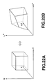
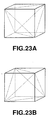
- (N -1) 3 cubes corresponding to N 3 measured data in the CMY color space as shown in FIG. 22A will be considered here.
- an area corresponding to this cube is taken into the L*a*b* color space, it will be a distorted hexahedron as shown in FIG. 22B.
- FIG. 22 only one cube in the CMY color space and only one hexahedron in the L*a*b* color space are shown for the simplicity of the illustration. However, it should be assumed that actually there are (N-1) 3 cubes and (N-1) 3 hexahedrons in the CMY color space and L*a*b* color space, respectively.
- each hexahedron is divided into five cubes as shown in FIGS. 23A and 23B, and it is judged whether the grid in the L*a*b* color space is included in any of the cubes assumed in the L*a*b* color space. If the grid in the L*a*b* color space is inside any of the cubes, a color corresponding to the grid will exist inside the color gamut of the CMY color space corresponding to the device. In this case, the operation goes to step S2 where it is search in which of the cubes the grid exists.
- the tetrahedron in the L*a*b* color space corresponds one to one to a one in the CMY color space. Therefore, if ⁇ ⁇ 0, ⁇ ⁇ 0, ⁇ ⁇ 0 and ⁇ + ⁇ + ⁇ ⁇ 1 hold in any one of the tetrahedrons in the L*a*b* color space, the point P on the grid in the L*a*b* color space will be included in a color gamut of the CMY color space corresponding to the device.
- step S3 the tetrahedron is interpolated to determine a point P in the CMY color space corresponding to the point P (L* p , a* p , b* p ) in the L*a*b* color space.
- the coordinates of the vertexes of the tetrahedron in the L*a*b* color space are (L* 0 , a* 0 , b* 0 ), (L* 1 , a* 1 , b* 1 ), (L* 2 , a* 2 , b* 2 ) and (L* 3 , a* 3 , b* 3 ), respectively, as shown in FIG.
- the point P'(C p , m p , y p ) in the CMY color space, corresponding to the point P (L* p , a* p , b* p ) in the L*a*b* color space is determined by a linear interpolation as in the following equation (3-2).
- a chromatic value in the CMY color space corresponding to the chromatic value on the grid in the L*a*b* color space is determined as in the above, namely, when (C p , m p , y p ) corresponding to (L* p , a* p , b* p ) is determined, the value of each CMY signal component corresponding to the grid at which the lines dividing the L*a*b* color space intersect each other is determined and registered into the forward lookup table at step S4.
- step S1 if the point on the grid in the L*a*b* color space is judged at step S1 not to be included in any of the tetrahedrons.
- the chroma signal corresponding to that point is outside the color gamut of the device signal and needs to have the color gamut reduced.
- the operation goes to step S5 where the color difference formula essential in the present invention is utilized for the color gamut reduction.
- the color difference formula essential in the present invention is utilized for the color gamut reduction.
- any whose difference from the color on the grid in the L*a*b* color space is the smallest is determined and its chromatic value is calculated. This color gamut reduction will further be described later.
- a color gamut reduction is effected to determine a chromatic value in the CMY color space, corresponding to a chromatic value at the grid in the L*a*b* color space. Based on the determined chromatic value in the CMY color space, a value of each CMY signal component corresponding to the grid at which the lines dividing the L*a*b* color space intersect each other is determined and registered into the backward lookup table, as at step S4.
- the color gamut reduction is to be done when it is judged that a chromatic signal corresponding to a grid in the L*a*b* color space is outside the color gamut of the device signal, to determine a point in the CMY color space, corresponding to a point on the grid in the L*a*b* color space.
- an L*a*b* signal outside a color gamut of the CMY color space corresponding to the device is subjected to color gamut reduction to determine a value of each CMY signal component corresponding to a value of each L*a*b* signal component.
- CMY signal components are represented by 0, 1, ..., 254 and 255, respectively.
- components of the CMY color space corresponding to the device are indicated simply with C, M and Y, respectively.
- a chromatic value in the L*a*b* color space being outside the color gamut of the CMY color space corresponding to the device and whose color gamut is to be reduced will be referred to as "to-be-reduced L*a*b* chromatic value” hereinafter.
- a chromatic value in the CMY color space, determined by the color gamut reduction will be referred to as "reduced CMY chromatic value” hereinafter.
- initial values are set for variables i, j and k intended to maintain values of CMY signal components and a variable ⁇ E min intended to maintain a minimum color difference. More specifically, zero is set for each of the variables i, j and k while a predetermined sufficiently large value A is set for the variable ⁇ E min .
- step S13 a color difference between a to-be-reduced L*a*b* chromatic value and the chromatic value in the L*a*b* color space, having been determined at step S12, is calculated.
- the color difference formula used to calculate the color difference ⁇ E is essential in the present invention. The color difference formula will further be described later.
- step S14 ⁇ E and ⁇ E min are compared with each other.
- ⁇ E ⁇ ⁇ E min the operation goes to step S15.
- ⁇ E is not smaller than ⁇ E min , the operation goes to step S17.
- step S15 the color difference ⁇ E having been determined at step S13 is set for the variable ⁇ E min .
- step S16 the current CMY value (namely, values of variables i, j and k) is stored in the memory, and thereafter the operation goes to step S17.
- the CMY value for storage into the memory will be updated each time the operation passes by step S16.
- step S17 one is added to any of the variables i, j and k which will not exceed 255 after the addition. Namely, each time the operation passes by step S17, the variables i, j and k are increased to 1, 0 and 0; 1, 1 and 0; 1, 1 and 1; 2, 1 and 1; ..., and then to 255, 255 and 255, respectively.
- step S18 it is judged whether the variables i, j and k have reached 255, the upper limit of each CMY signal component. If the variables have not yet reached 255, the operation goes back to step S12 and the procedure from step S12 to S18 are repeated. When the variables i, j and k have reached 255, the operation goes to step S19.
- the values of the variables i, j and k stored in the memory are outputted as reduced CMY chromatic values.
- CMY chromatic value a point in the CMY color space (namely, reduced CMY chromatic value) corresponding to a point on the grid in the L*a*b* color space (namely, to-be-reduced L*a*b* chromatic value).
- the chroma difference ⁇ C* and hue difference ⁇ H* are defined by the following equations (4-4) to (4-7):
- C 1 a 1 2 + b 1 2 1 / 2
- ⁇ E ⁇ L * ⁇ C * ⁇ H * ⁇ Kll Klc Klh Kcl Kcc Kch Khl Khc Khh ⁇ ⁇ L * ⁇ C * ⁇ H * 1 / 2
- ⁇ E ⁇ L * Kl 2 + ⁇ C * Kc 2 + ⁇ H * Kh 2 + ⁇ L * ⁇ ⁇ C * Klc + ⁇ C * ⁇ ⁇ H * Klc + ⁇ H * ⁇ ⁇ L * Khl
- ⁇ L* is a lightness difference
- ⁇ C* is a chroma difference
- ⁇ H* is a hue difference
- K l , K c , K h , K ll , K lc , K lh , K cl , K cc , K ch , K hl , K hc and K hh are predetermined constants or functions of a
- the predetermined constants K ll , K cc and K hh should preferably be set to meet the following equation (4-10).
- the predetermined constants K l , K c and K h should preferably be set to meet the following equation (4-11): K cc ⁇ K hh ⁇ K ll K c ⁇ K h ⁇ K l
- ⁇ L BFD L 2 ⁇ ⁇ ⁇ BFD - L 1 ⁇ ⁇ ⁇ BFD ⁇
- the above equation is a so-called BFD color difference formula.
- the color difference E By defining the color difference E by this formula, it is made possible to lessen very much the perception gap between a color having the to-be-reduced L*a*b* chromatic value.
- a color difference formula like the equation (5-1) it is made possible to well reduce the color gamut of a blue area which has been a large problem in the conventional color gamut reduction, without causing the blue area not to be reddish.
- the color gamut conversion table creating apparatus is embodied as a computer system adapted to execute the program (the color gamut conversion table creating program) in which the operations in the flow charts shown in FIGS. 20 and 26, for example, are stated. That is, by executing the color gamut conversion table creating program having stated therein the operations included in the flow charts shown in FIGS. 20 and 26, for example, the color gamut conversion table creating apparatus executes the operations included in the flow charts shown in FIGS. 20 and 26 to create a color gamut conversion table.
- the image processor according to the present invention will be described herebelow concerning an image processor which uses a device profile in which the color gamut conversion table having bee created as in the above to convert, for outputting, an image from a predetermined input device to an image corresponding to a color gamut of a predetermined output device.
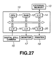
- the image processor is generally indicated with a reference 10.
- the image processor 10 is adapted to convert a color signal inputted from a predetermined input device to a color signal in a device-independent color space and then convert the color signal to a color signal which can be dealt with by an output device such as a monitor, printer or the like.
- the image processor 10 includes a central processing unit (CPU) 11 which effect a variety of data processing, a random access memory (RAM) 12 used as necessary during a data processing by the CPU 11, a first interface 14 controlling interfacing with an external memory 13, a second interface 16 controlling interfacing with a digital still camera 15, a third interface 18 controlling interfacing with a monitor 17, and a fourth interface 20 controlling interfacing with a printer 19.
- CPU central processing unit
- RAM random access memory
- the external memory 13 stores an image processing program having stated therein operations for converting an image from a predetermined input device to an image corresponding to the color gamut of a predetermined output device, a device profile used in the color signal conversion, etc.
- the CPU 11 reads a program previously stored in the external memory 13 via the first interface 14, and uses an area of the RAM 12 for a variety of date processing as necessary according to the program. More specifically, the CPU 11 reads an image processing program from the external memory 13 and converts an image from the predetermined input device to an image corresponding to the color gamut of the predetermined output device. At this time, the CPU 11 reads also a device profile from the external memory 13 and converts the color gamut based on the device profile.
- the second interface 16 controls interfacing with the digital still camera 15.
- a video signal acquired by taking a photo of an object by the use of the digital still camera 15 is supplied to the image processor 10 via the second interface 16.
- the third interface 18 controls interfacing with the monitor 17. A signal acquired as a result of a data processing in the CPU 11 is outputted to the monitor 17 via the third interface 18.
- the fourth interface 20 controls interfacing with the printer 19. A signal acquired as a result of a data processing in the CPU 11 is outputted to the printer 19 via the fourth interface 20.
- the image processor 10 functions as will be seen from the following description made concerning a conversion of an RGB signal supplied from the digital still camera 15 to a CMY signal and outputting the CMY signal to the printer 19, by way of example.
- the following function will be performed by the image processor 10 by reading an image processing program from the external memory 13 and executing the program by means of the CPU 11.
- a video signal (RGB signal) acquired by taking a photo of an object by means of the digital still camera 15 is supplied to the image processor 10.
- the CPU 11 will receive the RGB signal from the digital still camera 15 via the second interface 16.
- the CPU 11 will read from the external memory 13 via the first interface 14 a device profile in which a color gamut conversion table having stated therein a correspondence between the RGB signal and L*a*b* signal for color gamut conversion from the RGB signal to L*a*b* signal. Based on the device profile, the CPU 11 will convert the RGB signal to an L*a*b* signal in a device-independent CIE/L*a*b* color space.
- step S33 Next at step S32, the CPU 11 will read from the external memory 13 via the first interface 14 a device profile in which a color gamut conversion table having stated therein a correspondence between the L*a*b* signal and CMY signal for color gamut conversion from the L*a*b* signal to CMY signal. Based on the device profile, the CPU 11 will convert the L*a*b* signal to a CMY signal corresponding to the printer 19.
- step S34 the CMY signal thus acquired is supplied from the image processor 10 to the printer 19.
- the CPU 11 will supply the CMY signal having been acquired as in the above to the printer 19 via the fourth interface 20.
- the image processor 10 convert an image from a predetermined input device (digital still camera 15 in the above example) to an image corresponding to a color gamut of a predetermined output device (printer 19 in the above example).
- the digital still camera 15 is used as an input device, and monitor 17 and printer 19 are used as output devices.
- devices usable in the present invention are not limited such devices but they may of course be any one which could input and output an image data.
- a device profile in which a color gamut conversion table is defined is prepared beforehand and a color signal is converted based on the device profile. It should be noted, however, that each time a color signal is converted, it is possible to effect calculations for color gamut reduction based on the color difference formula given by the previously mentioned equation (4-8) or (4-9).
- a device signal is converted once to a color signal in a device-independent color space.
- a color signal in a device-dependent color space may be converted directly to a color signal in any other device-dependent color space without the conversion to a color signal in the device-independent color space.
- the color gamut reduction has been described, for example, which uses a define profile in which a color gamut conversion table is defined.
- the present invention is not limited to use of such a device profile is used, but can be applied to mapping of a color not reproducible even with a physical model or the like. That is, the present invention has a wide applicability and is applicable widely to mapping in a color gamut of an output device of a color outside the output device color gamut and thus not reproducible.
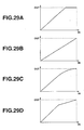
- FIGS. 29A to 29D the methods of color gamut reduction can be classified into “clipping”, “linear reduction” and “nonlinear reduction”.
- FIG. 29A shows a relation between an input and output when clipping is made for color gamut reduction
- FIG. 29B shows a relation between an input and output when a linear reduction is done for color gamut reduction
- FIGS. 29C and 29D show a relation between an input and output when a nonlinear reduction is made for color gamut reduction.
- the clipping is such that a color inside the color gamut of an input device but outside the color gamut of an output device is mapped along the profile of the output device color gamut so that the color inside the output device color gamut will not change.
- the linear reduction is such that a whole color gamut of an input device is linearly reduced to a color gamut of an output device.
- the nonlinear reduction is such that a nonlinear function is used to reduce an entire color gamut of an input device to a color gamut of an output device.
- This method is an intermediate one between the above two methods and permits to maintain the gradation and chroma to some extent.
- the clipping, linear reduction and nonlinear reduction have been proposed for the one- and two-dimensional color gamut reductions, respectively.
- the one- and two-dimensional color gamut reductions if an original image has a very high chroma and thus a third dimension such as an image produced by the computer graphics, among others, the features of the image will be rather lost.
- the present invention provides a three-dimensional reduction of color gamut.
- the L*a*b* is subjected to polar coordinate transformation to an L*C*h signal by which three attributes (lightness, chroma and hue) of a color can be represented.
- a color gamut reduction is effected in the polar coordinate space, and then the L*C*h signal is converted to L*a*b* signal again. Further, the color signal is converted to cyan (C), magenta (M), yellow (Y) and black (K) being output image color signals to form an image by means of the printer being an output device.
- the input and output image color signals may be ones in any of RGB color space, CMY color space, CMYK color space, YCC color space, etc.
- the color space may be any one of XYZ color space, L*a*b* color space, L*u*v* color space, etc.
- the color space should desirably be a one suitable for the visual characteristics of the human eyes.
- the patterns of color gamut shape include a one in which the color gamut of the printer is completely included in that of the printer as shown in FIG. 31 (this color gamut shape will be called "shape 1") and a one in which the monitor color gamut has a part thereof larger than the printer color gamut while the printer color gamut has a part thereof larger than the monitor color gamut as shown in FIG. 32 (this color gamut shape will be called “shape 2").
- the color gamut varies in shape from one device to another, so that all colors cannot physically be reproduced.
- the color gamut reduction is to map a monitor color gamut not reproducible by a printer in a color gamut of the printer.
- the color gamut reduction has to be done in such a manner that an input image will be reproduced to have a more natural appearance.
- the three-dimensional color gamut reduction is effected in the linear or nonlinear manner.
- FIG. 33 A flow of operations made for the three-dimensional color gamut reduction is roughly shown in FIG. 33.
- an input image color signal is given as an L*C*h_in (point P) in a device-independent color space, and converted to L*C*h_out by the color gamut reduction.
- L*C*h_in point P
- L*C*h_out L*C*h_out
- L*C*h_in will be taken as a data as it is after the color gamut reduction. That is, L*C*h_in is outputted as L*C*h_out as it is.
- first position information on the point P is acquired.
- the position is determined based on a ratio (m:n) between a distance of the point P from the outer wall of the colorimetric area and a distance from the outer wall of the monitor color gamut.
- distance referred to herein is a distance along a straight line, not always any shortest distance from each outer wall, as will be described later.
- an imaginary color gamut (will be referred to as "output device imaginary color gamut” hereinafter) is set in the printer color gamut.
- the profile of this imaginary color gamut is defined for a constant ratio (x:y) to be attained between the distance from the outer wall of the colorimetric area and distance from the outer wall of the printer color gamut. Note that this "distance” is a distance along a straight line, not always any shortest distance from each outer wall, as will be described later.
- the ratio (x:y) is calculated using a predetermined reduction function which may be a linear function or a nonlinear function such as a power function, S-curve function or the like.
- a predetermined evaluation function is used to make a search for a reduction or expansion destination of the point P between the output device imaginary color gamut and point P.
- the predetermined evaluation function is for example a color difference formula given by the equation (4-8) or (4-9). That is, the point P is mapped along the profile of the output device imaginary color gamut by reduction or expansion so that the color difference ⁇ E given by the equation (4-8) or (4-9) is minimum.
- the chromatic value at the mapping destination is outputted as L*C*h_out.
- the colorimetric area may absolutely be set using the parameter K or may be set in relation to the printer and monitor color gamuts taken as a reference.
- the absolute setting of the colorimetric area is to set the colorimetric area irrespectively of the color gamut shapes of the printer and monitor.
- the colorimeter area is set as a triangle passing through the parameter K.
- the relative setting of the colorimetric area is to set the colorimetric area in relation to the color gamuts of the printer and monitor.
- the colorimetric area is set by relatively reducing the printer color gamut in a direction.
- the colorimetric area may be set in relation to the printer color gamut as shown in FIG. 37. Otherwise, the colorimetric area may be set in relation to a color gamut common to the monitor and printer as shown in FIGS. 38.
- the parameter K may be of any value if only it is within the printer color gamut.
- the parameter K may be set on a lightness determined to have a maximum chroma inside the printer color gamut, as shown in FIG. 37. Otherwise, the parameter K may be set on a lightness determined to have a maximum chroma in the color gamut common to the printer and monitor, as shown in FIG. 38.
- the parameter K may be set on the straight line extending from the point having a maximum chroma in the printer color gamut to a point having a predetermined chromatic value, or it may be set on a straight line extending from a point having the maximum chroma in the color gamut common to the printer and monitor to a point having the predetermined chromatic value.
- the parameter K should desirably be optimized taking in consideration the difference in color gamut between devices and color distribution of an input image signal. For example, the larger the difference between the color gamut shape of the output device and that of the input device, the smaller the parameter should desirably be. Also, the more the input image signal outside the output device color gamut, the smaller the parameter K should desirably be. In any case, however, the chroma Ck of the parameter K should be Ck > (Cpmax/2).
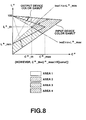
- the colorimetric area is set as a not-to-reduced area inside the printer color gamut.
- an area obtained by subtraction of the colorimetric area from the monitor color gamut is "area A”
- an area obtained by subtraction of the colorimetric area from the printer color gamut is "area B”
- a common area to the areas A and B is "area C”
- the color gamut reduction is effected by reducing or expanding the area A to the area B and/or C. Note that when the monitor and printer color gamuts have the shape 1 as in the above, the areas B and C will coincide with each other.
- the colorimetric area is set in relation to the printer color gamut with the parameter K set on the straight line of lightness of the color gamut having the maximum chroma in the hue plane of the point P.
- position information of the point P is first acquired.
- the position of the point P is determined based on a ratio between the distance from the outer wall of the colorimetric area and that from the outer wall of the monitor color gamut.
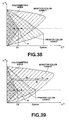
- this "distance" is a distance along a straight line, not always any shortest distance from each outer wall. That is, the value of the ratio acquired as the position information of the point P may be obtained from an interior division ratio on the equal lightness straight line passing through the point P as shown in FIG. 39, for example, or from an interior division ratio on a straight line passing through the point P and a point on the achromatic axis as shown in FIGS. 40 and 41, for example.
- the position information of the point P will be described on the assumption that it is acquired from the interior division ratio on the equal lightness straight line passing through the point P as shown in FIG. 39.
- the ratio between the distance from the outer wall of the colorimetric area and that of the monitor color gamut is m:n.
- an output device imaginary color gamut is set as shown in FIG. 42.
- the output device imaginary color gamut is a color gamut imaginarily set inside the printer color gamut, and its outer wall is set so that the ratio between the distance from the outer wall of the colorimetric area and that from the outer wall of the printer color gamut is constant (x:y).
- this "distance” is a distance along a straight line, not always any shortest distance from each outer wall.
- the ratio (x:y) is calculated using a predetermined reduction function. The relation of this ratio (x:y) with the ratio (m:n) acquired as the position information of the point P will further be described later.
- a point on the straight light used for acquisition of the position information of the point P (namely, the equal lightness straight line passing through the point P) and where the ratio between the distance from the outer wall of the colorimetric area and that from the outer wall of the printer color gamut is x:y, is taken as a point Q.
- Straight lines are assumed which is parallel to the straight line PQ for all the lightness and hue.
- the outer wall of the output device imaginary color gamut is an assembly of points where the ratio between the outer wall of the colorimetric area and that from the outer wall of the printer color gamut is x:y on such straight lines.
- the output device imaginary color gamut may be set irrespectively of the straight line used for the acquisition of the position information of the point P. As shown in FIGS. 43 and 44 for example, a straight line passing through a point on the achromatic axis may be assumed and a point on this straight line where the ratio between the distance from the outer wall of the colorimetric area and that from the outer wall of the printer color gamut is x:y, be taken as the point Q.
- the outer wall of the output device imaginary color gamut may be an assembly of points on straight lines extending radially in all directions from a point on the achromatic axis, for example, and where the ratio between the distance from the outer wall of the colorimetric area and that from the outer wall of the printer color gamut is x:y.
- the outer wall of the output device imaginary color gamut is defined as an assembly of the points Q.
- the ratio between the distance from the outer wall of the colorimetric area and that from the outer wall of the printer color gamut is x:y.
- the ratio (x:y) is calculated using a predetermined reduction function based on the ratio (m:n) acquired as the position information of the point P. How to calculate the ratio (x:y) will be described below:
- Cmon indicates a chroma at an intersection of the straight line passing through the points P and Q with the outer wall of the monitor color gamut
- Cprn indicates a chroma at an intersection of the straight line passing through the points P and Q with the outer wall of the printer color gamut
- Ccol indicates a chroma at an intersection of the straight line passing through the points P and Q with the outer wall of the colorimetric area
- Cpin indicates a chroma at the point P
- Cpout indicates a chroma at the point Q.
- a linear function is sued to determine the chroma Cpout at the point Q corresponding to the chroma Cpin at the point P.
- An interior division ratio between Ccol and Cprn at the chroma Cpout is determined and taken as the ratio (x:y).
- the ratio (x:y) may be calculated using a nonlinear function.
- the nonlinear function is used to determine the chroma Cpout at the point Q corresponding to the chroma Cpin at the point P as shown in FIGS. 46 and 47.
- An interior division ratio between Ccol and Cprn at the Cpout is determined and taken as the ratio (x:y).
- the ratio (m:n) acquired as the position information of the point P is determined as the interior division ratio on the straight lines passing trough the point P and a point on the achromatic axis as shown in FIGS. 40 and 41, the lightness and chroma are linearly or non-linearly converted. Also in this case, the point Q and ratio (x:y) can be determined as in FIGS. 45 to 47 except that both the lightness and chroma are taken in consideration.
- a color signal corresponding to the point P is mapped along the profile of the output device imaginary color gamut.
- a destination of the mapping is determined based on an evaluation value acquired using a predetermined evaluation function, for example. That is, the predetermined evaluation function is used to make a search for a destination of reduction or expansion of the point P, for example, and the mapping is effected for the reduced color signal to be optimum.
- the color difference formula given by the equation (4-8) or (4-9) for example is used herein as the predetermined evaluation function. That is, the point P is mapped along the profile of the output device imaginary color gamut by reducing or expanding the point P so that the color difference ⁇ E given by the equation (4-8) or (4-9) is minimum.
- the chromatic value of the mapping destination is outputted as L*C*h_out.
- the concrete examples of the color difference formula given by the equation (4-8) or (4-9) include the so-called ⁇ E 94 color difference formula given by the following equation (6-1), so-called BFD color difference formula given by the following equation (6-2), etc.
- ⁇ E 94 ⁇ L * k L ⁇ S l 2 + ⁇ C * k C ⁇ S C 2 + ⁇ H * k H ⁇ S H 2
- E BFD l c ⁇ ⁇ L BFD l 2 + ⁇ C * c ⁇ D C 2 + ⁇ H * D H 2 + R T ⁇ C * c ⁇ ⁇ D C ⁇ ⁇ H * D H
- the ⁇ E 94 color difference formula given by the equation (6-1) is used as the evaluation function and the point P is mapped along the profile of the output device imaginary color gamut for the color difference to be minimum.
- the BFD color difference formula given by the equation (6-2) is used as the evaluation function and the point P is mapped along the profile of the output device imaginary color gamut for the color difference to be minimum.
- evaluation function used for determination of a mapping destination is not limited to the above. Therefore, if a color space, color difference formula, etc. suitable for the human visual sensation are defined hereafter, they may be used as the evaluation function.
- the evaluation function and its parameters may be the same for all color signals to be subjected to color gamut reduction, but they may be changed for each hue and each color area. Therefore, for those of color signals having to be reduced in color gamut which are outside the printer color gamut, the lightness, chroma and hue may be three-dimensionally reduced while for those which are inside the printer color gamut, the lightness and chroma may be two-dimensionally reduced.
- a color difference formula given by the following equation (6-4) is used as the evaluation function and mapping is made along the profile of the output device imaginary color gamut for the color difference to be minimum.
- K hh should preferably be defined as a function of the distance from the outer wall of the printer color gamut.
- a color signal whose ratio between the distance from the outer wall of the colorimetric area and that from the outer wall of the monitor color gamut is m:n is mapped along the profile of the output device imaginary color gamut whose ratio between the distance from the outer wall of the colorimetric area and that from the outer wall of the printer color gamut is x:y.
- the above processing is effected all the to-be-reduced input image color signals.
- the linear or nonlinear reduction can be adopted to effect a color gamut reduction using the three-dimensions, namely, lightness, chroma and hue.
- FIGS. 48 and 49 show the concept of the above color gamut reduction.
- a color signal in a certain plane inside the monitor color gamut is mapped along the profile of the output device imaginary color gamut corresponding to the plane
- the color signal in the certain plane inside the monitor color gamut is mapped along the outermost contour of the output device imaginary color gamut corresponding to the plane. That is, an input image color signal is mapped along any profile of the output device imaginary color gamut set inside the printer color gamut, whereby the input image color signal is converted to a color signal corresponding to the printer color gamut.
- the monitor and printer color gamuts have the aforementioned shape 2 (namely, the monitor color gamut is partially larger than the printer color gamut and the printer color gamut is partially larger than the monitor color gamut), the nearly same color gamut reduction as in the above can be effected. More particularly, when the monitor and printer color gamuts have the shape 2, the color gamut reduction should be done as in the above if the area A (an area obtained by subtraction of the colorimetric area from the monitor color gamut) is reduced or expanded to the area B (an area obtained by subtraction of the colorimetric area from the printer color gamut). On the other hand, if the area A is reduced or expanded to the area C (a common area to the areas A and B), the printer color gamut referred to in the above description should be changed to the common color gamut to the monitor and printer.
- the human visual sensation can be taken in consideration in the color gamut reduction which will be excellent being suitable for the human visual sensation.
- the color gamut reduction according to the present invention permits to reproduce an image in colors very near those of an original image, without much spoiling the image contrast, sharpness and gradation of the image
- a color signal outside the output device color gamut has to be reduced in color gamut.
- the present invention permits to convert a color signal outside the output device color gamut more approximate to the input device color gamut before reducing the color gamut of the color signal outside the output device color gamut and converting the input image to an image corresponding to the output device color gamut.
Claims (20)
- Bildprozessor (10), der eingerichtet ist, ein Bild - zur Ausgabe - von einer vorher festgelegten Eingangseinrichtung (15) in ein Bild entsprechend einer Farbskala einer entsprechenden Ausgangseinrichtung (19) umzusetzen, wobei der Bildprozessor aufweist:eine Einrichtung zum Reduzieren, wenn die Ausgangseinrichtungs-Farbskala von einer Farbskala der Eingangseinrichtung verschieden ist, der Farbskala des Farbsignals außerhalb der Ausgangseinrichtungs-Farbskala in der Richtung eines minimalen Werts der Farbdifferenzformeln, welche durch die folgende Gleichung (1) oder (2) angegeben werden:wobei ΔL* eine Differenz in der Helligkeit ist, ΔC* eine Differenz in Chroma ist; ΔH* eine Differenz im Farbton ist; K1, Kc, Kh, Kll, Klc, Klh, Kcl, Kcc, Kch, Khl, Khc, bzw. Khh vorher festgelegte Konstanten sind oder Funktionen einer Helligkeit L*, Chroma C* bzw. eines Farbtons h* ; und wobei die Vektorproduktausdrücke ΔL* ΔC*, ΔC* ΔH* und ΔH* ΔL* zum Wert ΔE beitragen.


- Vorrichtung nach Anspruch 1, wobei, um die Farbskala der Eingangseinrichtung zu reduzieren, die Farbskala-Reduziereinrichtung betriebsfähig ist, eine imaginäre Farbskala für eine Ausgangseinrichtung für das Farbsignal des Bilds von der Eingangseinrichtung als eine imaginäre Farbskala in der Ausgangsfarbskala einzustellen, um die Farbskala des Farbsignals des Bilds von der Eingangseinrichtung in der Richtung einer minimalen Farbdifferenz △E zu reduzieren, die durch die Gleichung (1) oder (2) angegeben wird, und das Farbsignal des Eingangsbilds längs der äußersten Kontur der imaginären Farbskala für die Ausgangseinrichtung aufzulisten, um dadurch - zur Ausgabe - das Bild von der vorher festgelegten Eingangseinrichtung in das Bild entsprechend der Farbskala der vorher festgelegten Ausgangseinrichtung umzusetzen.
- Vorrichtung nach Anspruch 2, wobei, um eine Farbskala zu reduzieren, die Farbskala-Reduziereinrichtung betriebsfähig ist, innerhalb der Ausgangseinrichtungs-Farbskala einen nicht-zu-reduzierenden Bereich festzulegen, wo die Farbskala nicht reduziert werden soll, während die imaginäre Farbskala für die Ausgangseinrichtung außerhalb des nicht-zu-reduzierenden Bereichs eingestellt wird; und
um - zur Ausgabe - das Bild von der vorher festgelegten Eingangseinrichtung in ein Bild entsprechend der Farbskala der vorher festgelegten Ausgangseinrichtung umzusetzen, wobei die Farbskala-Reduziereinrichtung außerdem betriebsfähig ist, ein Farbsignal innerhalb des nicht-zu-reduzierenden Bereichs unverändert ohne Reduzieren von dessen Farbskala auszugeben. - Vorrichtung nach Anspruch 3, wobei die Farbskala-Reduziereinrichtung betriebsfähig ist, den nicht-zu-reduzierenden Bereich in Bezug auf die Eingangseinrichtungs-Farbskala und/oder die Ausgangseinrichtungs-Farbskala auf Basis der Eingangseinrichtungs-Farbskala und/oder der Ausgangseinrichtungs-Farbskala einzustellen.
- Vorrichtung nach Anspruch 2, wobei, um eine Farbskala zu reduzieren, wenn das Farbsignal des Bilds von der Eingangseinrichtung innerhalb der Farbskala der Ausgangseinrichtung ist, die Farbskala-Reduziereinrichtung betriebsfähig ist, lediglich die Helligkeit und Chroma des Farbsignals zu ändern, während der Farbton des Farbsignals beibehalten wird; und
wenn das Farbsignal des Bilds von der Eingangseinrichtung außerhalb der Farbskala der Ausgangseinrichtung ist, die Farbskala-Reduziereinrichtung betriebsfähig ist, die Helligkeit, Chroma und Farbton des Farbsignals zu ändern. - Vorrichtung nach einem der vorhergehenden Ansprüche, wobei


- Bildverarbeitungsverfahren zum Reduzieren, wenn die Farbskala einer Ausgangseinrichtung (19) von der einer Eingangseinrichtung (15) verschieden ist, wenn - zur Ausgabe - ein Bild von einer vorher festgelegten Eingangseinrichtung in ein Bild entsprechend der Farbskala einer entsprechenden Ausgangseinrichtung umgesetzt wird, die Farbskala eines Farbsignals außerhalb der Ausgangseinrichtungs-Farbskala in der Richtung eines Minimalwerts der Farbdifferenz ΔE durch die folgende Gleichung (1) oder (2) angegeben wird:


wobei ΔL* eine Differenz in der Helligkeit ist, ΔC* eine Differenz in Chroma ist; ΔH* eine Differenz im Farbton ist; Kl, Kc, Kh, Kll, Klc, Klh, Kcl, Kcc, Kch, Khl, Khc, bzw. Khh vorher festgelegte Konstanten sind, oder Funktionen einer Helligkeit L*, Chroma C* bzw. Farbton h*; und wobei die Vektorproduktausdrücke ΔL* ΔC*, ΔC* ΔH* und ΔH* ΔL zum Wert ΔE beitragen. - Verfahren nach Anspruch 7, wobei, um die Farbskala der Eingangseinrichtung zu reduzieren, eine imaginäre Farbskala für die Ausgangseinrichtung für das Farbsignal des Bilds von der Eingangseinrichtung als eine imaginäre Farbskala in der Ausgangsfarbskala eingestellt wird;
die Farbskala des Farbsignals des Bilds von der Eingangseinrichtung in der Richtung einer minimalen Farbdifferenz △E reduziert wird, die durch die Gleichung (1) oder (2) angegeben wird, und das Farbsignal des Bilds von der Eingangseinrichtung längs der äußersten Kontur der imaginären Farbskala für die Ausgangseinrichtung aufgelistet wird, wodurch - zur Ausgabe - das Bild von der vorher festgelegten Eingangseinrichtung in das Bild entsprechend der Farbskala der vorher festgelegten Ausgangseinrichtung umgesetzt wird. - Verfahren nach Anspruch 8, wobei, um eine Farbskala zu reduzieren, ein nicht-zu-reduzierender Bereich, wo die Farbskala nicht zu reduzieren ist, innerhalb der Farbskala für die Ausgangseinrichtung eingestellt wird, während die imaginäre Farbskala für die Ausgangseinrichtung außerhalb des nicht-zu-reduzierenden Bereichs eingestellt wird; und
das Bild von der vorher festgelegten Eingangseinrichtung - zur Ausgabe - in ein Bild entsprechend der Farbskala einer vorher festgelegten Ausgangseinrichtung umgesetzt wird, und ein Farbsignal innerhalb des nicht-zu-reduzierenden Bereichs unverändert ohne dessen Farbskala zu reduzieren ausgegeben wird. - Verfahren nach Anspruch 9, wobei der nicht-zu-reduzierende Bereich in Relation zur Farbskala für die Eingangseinrichtung und/oder die Farbskala für die Ausgangseinrichtung auf Basis der Farbskala für die Eingangseinrichtung und/oder Ausgangseinrichtung eingestellt wird.
- Verfahren nach Anspruch 7, wobei, um eine Farbskala zu reduzieren, wenn das Farbsignal des Bilds von der Eingangseinrichtung innerhalb der Farbskala der Ausgangseinrichtung ist, lediglich die Helligkeit und Chroma des Farbsignals geändert werden, während der Farbton beibehalten wird; und
wenn das Farbsignal des Bilds von der Eingangseinrichtung außerhalb der Farbskala der Ausgangseinrichtung ist, die Helligkeit, Chroma und Farbton des Farbsignals geändert werden. - Verfahren nach einem der Ansprüche 7 und 11, wobei


- Bildungsvorrichtung für eine Farbskala-Umsetzungstabelle, die ausgebildet ist, eine Farbskala-Umsetzungstabelle zu bilden, auf die Bezug genommen wird, wenn - zur Ausgabe - ein Eingangsfarbsignal von einer vorher festgelegten Eingangseinrichtung (15) in ein Farbsignal entsprechend der Farbskala einer vorher festgelegten Ausgangseinrichtung umgesetzt wird, wobei die Vorrichtung aufweist:eine Bildungseinrichtung für eine Farbskala-Umsetzungstabelle zum Reduzieren der Farbskala einer von Farben innerhalb der Farbskala einer Eingangseinrichtungs-Farbskala, nicht innerhalb der Farbskala einer Ausgangseinrichtung, in der Richtung einer minimalen Farbdifferenz ΔE, welche durch die Gleichung (1) oder (2) angegeben wird, damit die Farbe einer Farbe innerhalb der Ausgangseinrichtungs-Farbskala entspricht, und Bilden - auf Basis des Ergebnisses der Korrespondenz - einer Farbskala-Umsetzungstabelle, welche Beziehungen zwischen Eingangseinrichtungs-Farbsignalen und Ausgangseinrichtungs-Farbsignalen zeigt:wobei ΔL* eine Differenz in der Helligkeit ist; ΔC* eine Differenz in Chroma ist; ΔH* eine Differenz im Farbton ist; Kl, Kc, Kh, Kll, Klc, Klh, Kcl, Kcc, Kch, Khl, Khc, bzw. Khh vorher festgelegte Konstanten sind, oder Funktionen einer Helligkeit L*, Chroma C* bzw. Farbton h*; und wobei die Vektorproduktausdrücke ΔL* ΔC*, ΔC* ΔH* und ΔH* ΔL zum Wert ΔE beitragen.


- Verfahren nach Anspruch 13, wobei


- Umsetzungsverfahren für eine Farbskala-Umsetzungstabelle, welches ausgebildet ist, eine Farbskala-Umsetzungstabelle zu bilden, auf die Bezug genommen wird, wenn zur - Ausgabe - ein Farbsignal, welches von einer vorher festgelegten Eingangseinrichtung zugeführt wird, in ein Farbsignal umgesetzt wird, welches der Farbskala einer vorher festgelegten Ausgangseinrichtung entspricht, wobei das Verfahren folgenden Schritt aufweist:Reduzieren der Farbskala einer von Farben innerhalb der Farbskala einer Eingangseinrichtungs-Farbskala, nicht innerhalb der Farbskala einer Ausgangseinrichtung, in der Richtung einer minimalen Farbdifferenz ΔE, welche durch die Gleichung (1) oder (2) angegeben wird, damit die Farbe einer Farbe innerhalb der Ausgangseinrichtungs-Farbskala entspricht, und auf Basis des Ergebnisses der Korrespondenz eine Farbskala-Umsetzungstabelle zu bilden, welche Beziehungen zwischen den Eingangseinrichtungs-Farbsignalen und den Ausgangseinrichtungs-Farbsignalen zeigt:wobei ΔL* eine Differenz in Helligkeit ist; ΔC* eine Differenz in Chroma ist; ΔH* eine Differenz im Farbton ist; Kl, Kc, Kh, Kll, Klc, Klh, Kcl, Kcc, Kch, Khl, Khc, bzw. Khh vorher festgelegte Konstanten sind oder Funktionen einer Helligkeit L*, Chroma C* bzw. Farbton h*; und wobei die Vektorproduktausdrücke ΔL* ΔC*, ΔC* ΔH* und ΔH* ΔL zum Wert ΔE beitragen.


- Verfahren nach Anspruch 15, wobei


- Aufzeichnungsmedium, auf dem ein Bildverarbeitungsprogramm oder das Bildverarbeitungsprogramm selbst aufgezeichnet ist, welches betriebsfähig ist, wenn dies auf einem Computer läuft, um die Verfahrensschritte nach einem der Ansprüche 7 bis 12 durchzuführen.
- Aufzeichnungsmedium nach Anspruch 17, wobei


- Aufzeichnungsmedium, auf dem ein Bildungsprogramm für eine Farbskala-Umsetzungstabelle oder das Umsetzungstabellen-Bildungsprogramm selbst aufgezeichnet ist, welches betriebsfähig ist, wenn dies auf einem Computer läuft, die Verfahrensschritte nach einem der Ansprüche 15 oder 16 durchzuführen.
- Aufzeichnungsmedium nach Anspruch 19, wobei


Applications Claiming Priority (4)
| Application Number | Priority Date | Filing Date | Title |
|---|---|---|---|
| JP1451599 | 1999-01-22 | ||
| JP1451599 | 1999-01-22 | ||
| JP11200838A JP2000278546A (ja) | 1999-01-22 | 1999-07-14 | 画像処理装置及び画像処理方法、色域変換テーブル作成装置及び色域変換テーブル作成方法、画像処理プログラムを記録した記録媒体、並びに色域変換テーブル作成プログラムを記録した記録媒体 |
| JP20083899 | 1999-07-14 |
Publications (3)
| Publication Number | Publication Date |
|---|---|
| EP1022897A2 EP1022897A2 (de) | 2000-07-26 |
| EP1022897A3 EP1022897A3 (de) | 2002-04-03 |
| EP1022897B1 true EP1022897B1 (de) | 2007-03-07 |
Family
ID=26350463
Family Applications (1)
| Application Number | Title | Priority Date | Filing Date |
|---|---|---|---|
| EP00300302A Expired - Lifetime EP1022897B1 (de) | 1999-01-22 | 2000-01-17 | Bildverarbeitung und Farbumwandlung |
Country Status (4)
| Country | Link |
|---|---|
| US (1) | US6437792B1 (de) |
| EP (1) | EP1022897B1 (de) |
| JP (1) | JP2000278546A (de) |
| DE (1) | DE60033713T2 (de) |
Families Citing this family (71)
| Publication number | Priority date | Publication date | Assignee | Title |
|---|---|---|---|---|
| US7280251B1 (en) | 1996-02-26 | 2007-10-09 | Rah Color Technologies | System and method for calibrating color printers |
| JP3960694B2 (ja) * | 1998-10-26 | 2007-08-15 | 富士通株式会社 | 色信号変換方法、色信号変換装置、記録媒体、デバイスドライバ及び色変換テーブル |
| US6618499B1 (en) * | 1999-06-01 | 2003-09-09 | Canon Kabushiki Kaisha | Iterative gamut mapping |
| US7177465B1 (en) * | 1999-07-16 | 2007-02-13 | Fuji Photo Film Co., Ltd. | Method of compressing/extending color reproducing space, color reproducing method and color reproducing apparatus |
| US6775028B1 (en) * | 2000-02-24 | 2004-08-10 | Lexmark International, Inc. | Non-linear method of mapping the lightness and chroma of a display device gamut onto a printing device gamut |
| US7102648B1 (en) | 2000-04-11 | 2006-09-05 | Rah Color Technologies Llc | Methods and apparatus for calibrating a color display |
| JP4306936B2 (ja) * | 2000-07-14 | 2009-08-05 | キヤノン株式会社 | 色処理装置および方法 |
| JP3896776B2 (ja) * | 2000-08-24 | 2007-03-22 | コニカミノルタビジネステクノロジーズ株式会社 | 画像データ符号化装置、画像データ符号化方法、画像形成装置及び記録媒体 |
| US20020027603A1 (en) * | 2000-09-01 | 2002-03-07 | Seiko Epson Corporation | Apparatus, method, signal and computer program product configured to provide output image adjustment for image files |
| JP2002094812A (ja) * | 2000-09-12 | 2002-03-29 | Canon Inc | 画像処理方法、装置および記録媒体 |
| US6642931B1 (en) * | 2000-10-05 | 2003-11-04 | Canon Kabushiki Kaisha | Dynamically-generated color look-up table |
| JP3692989B2 (ja) * | 2000-11-13 | 2005-09-07 | セイコーエプソン株式会社 | 画像表示システム、プロジェクタ、画像処理方法、プログラムおよび情報記憶媒体 |
| US6952493B2 (en) * | 2001-01-31 | 2005-10-04 | Hewlett-Packard Development Company, L.P. | System and method for gamut mapping using a composite color space |
| DE50109949D1 (de) * | 2001-04-05 | 2006-07-06 | Gretag Macbeth Ag | Verfahren zur Erzeugung einer Farbpalette |
| US7355745B2 (en) * | 2001-04-13 | 2008-04-08 | Hewlett Packard | Document-to-printer color gamut matching |
| US6882449B2 (en) * | 2001-06-18 | 2005-04-19 | Hewlett-Packard Development Company, L.P. | Space varying gamut mapping |
| WO2003001499A1 (fr) * | 2001-06-26 | 2003-01-03 | Seiko Epson Corporation | Systeme d'affichage d'images, projecteur, procede de traitement d'images et support d'enregistrement de donnees |
| US7046255B2 (en) * | 2001-06-28 | 2006-05-16 | Hewlett-Packard Development Company, L.P. | Hardware-based accelerated color correction filtering system |
| JP4217398B2 (ja) * | 2001-09-12 | 2009-01-28 | キヤノン株式会社 | 画像データ処理方法、画像データ処理装置、記憶媒体、及びプログラム |
| KR100438159B1 (ko) * | 2002-03-13 | 2004-07-01 | 삼성전자주식회사 | 색대역의 효율적인 저장과 이를 이용한 색신호 처리장치및 방법 |
| US7229146B2 (en) * | 2002-04-08 | 2007-06-12 | Agfa Graphics Nv | System and method for characterizing a printing device |
| EP1420233A1 (de) * | 2002-11-12 | 2004-05-19 | Gretag-Macbeth AG | Digitaler Farbstandard |
| JP2004200902A (ja) * | 2002-12-17 | 2004-07-15 | Nikon Corp | 画像処理装置、電子カメラ、及び画像処理プログラム |
| US7751081B2 (en) * | 2003-03-31 | 2010-07-06 | Lexmark International, Inc. | Gamut mapping by controlling minimum and maximum color changes |
| US20050024430A1 (en) * | 2003-07-14 | 2005-02-03 | Kress William C. | Printer profile mapping of input primaries to output primaries |
| US7474438B2 (en) * | 2003-07-31 | 2009-01-06 | Hewlett-Packard Development Company, L.P. | Wide gamut mapping method and apparatus |
| US7884964B2 (en) * | 2003-08-05 | 2011-02-08 | Xerox Corporation | Methods and systems for controlling out-of-gamut memory and index colors |
| US7251358B2 (en) * | 2003-11-13 | 2007-07-31 | Canon Kabushiki Kaisha | Color measurement profile with embedded characterization |
| KR100552695B1 (ko) | 2003-11-20 | 2006-02-20 | 삼성전자주식회사 | 칼라영상의 색조절방법 및 장치 |
| WO2005117412A1 (ja) * | 2004-05-27 | 2005-12-08 | Konica Minolta Photo Imaging, Inc. | 画像処理方法、画像処理プログラムおよび画像処理装置 |
| CN100399794C (zh) * | 2004-07-29 | 2008-07-02 | 友达光电股份有限公司 | 表现特定色彩空间的方法 |
| US8089489B2 (en) * | 2004-09-30 | 2012-01-03 | Lexmark International, Inc. | Method for converting a source gamut of an image to a destination gamut |
| JP4006431B2 (ja) * | 2004-10-28 | 2007-11-14 | キヤノン株式会社 | 画像処理方法及び画像処理装置 |
| JP4938761B2 (ja) * | 2005-04-04 | 2012-05-23 | コーニンクレッカ フィリップス エレクトロニクス エヌ ヴィ | 多原色ディスプレイのために信号を変換する方法 |
| KR100664958B1 (ko) * | 2005-07-11 | 2007-01-04 | 삼성전자주식회사 | 미리 정의된 데이터와 색특성 정보를 이용하여 최적 변환된영상을 출력하는 방법 및 프린터 |
| JP4594185B2 (ja) * | 2005-08-02 | 2010-12-08 | キヤノン株式会社 | 色処理方法およびその装置 |
| JP4632438B2 (ja) | 2005-08-02 | 2011-02-16 | キヤノン株式会社 | 色処理方法、並びに、ルックアップテーブルを作成する色処理装置およびその方法 |
| JP4533277B2 (ja) * | 2005-08-12 | 2010-09-01 | キヤノン株式会社 | 画像処理装置、画像処理方法およびテーブル作成方法 |
| US7965426B2 (en) | 2005-08-12 | 2011-06-21 | Canon Kabushiki Kaisha | Image processing apparatus and method for performing gamut mapping via device-independent standard color space |
| JP4534917B2 (ja) * | 2005-09-08 | 2010-09-01 | ソニー株式会社 | 色域圧縮方法、プログラム、色域圧縮装置 |
| US8432588B2 (en) * | 2005-10-25 | 2013-04-30 | Hewlett-Packard Development Company, L.P. | Color mapping |
| CN100392663C (zh) * | 2005-11-11 | 2008-06-04 | 杭州电子科技大学 | 远程色彩信息传递方法 |
| JP4573045B2 (ja) * | 2006-01-17 | 2010-11-04 | 富士ゼロックス株式会社 | 色信号対生成装置、色信号対生成方法、色処理装置、色処理方法、色信号対生成プログラム、色処理プログラム、記憶媒体 |
| CN101480107A (zh) | 2006-06-27 | 2009-07-08 | 皇家飞利浦电子股份有限公司 | 颜色导航系统 |
| JP4803666B2 (ja) * | 2006-06-30 | 2011-10-26 | 株式会社リコー | 画像処理装置、画像処理方法、プログラムおよび記録媒体 |
| JP2008048314A (ja) * | 2006-08-21 | 2008-02-28 | Fuji Xerox Co Ltd | 画像処理装置、画像処理プログラムおよび画像処理方法 |
| JP4363430B2 (ja) * | 2006-08-31 | 2009-11-11 | ソニー株式会社 | 色域変換装置、色域変換方法 |
| KR20080029410A (ko) * | 2006-09-29 | 2008-04-03 | 삼성전자주식회사 | 디스플레이 시스템 및 그 영상 처리 방법 |
| JP4802981B2 (ja) * | 2006-11-02 | 2011-10-26 | コニカミノルタエムジー株式会社 | 色変換テーブル作成プログラム、色変換テーブル作成装置及び色変換テーブル作成システム |
| JP4974762B2 (ja) * | 2007-05-28 | 2012-07-11 | キヤノン株式会社 | 色処理装置及び方法 |
| JP4971948B2 (ja) * | 2007-11-13 | 2012-07-11 | 株式会社リコー | 画像処理装置、画像処理方法、プログラムおよび記録媒体 |
| JP5105209B2 (ja) | 2007-12-04 | 2012-12-26 | ソニー株式会社 | 画像処理装置および方法、プログラム、並びに記録媒体 |
| JP4560741B2 (ja) | 2007-12-13 | 2010-10-13 | ソニー株式会社 | 情報処理装置および方法、プログラム、並びに情報処理システム |
| JP4517308B2 (ja) | 2007-12-13 | 2010-08-04 | ソニー株式会社 | 情報処理装置および方法、プログラム、並びに情報処理システム |
| JP4661878B2 (ja) * | 2008-01-23 | 2011-03-30 | ブラザー工業株式会社 | 変換テーブル作成装置、変換テーブル作成プログラム及び変換テーブル作成方法 |
| US8542246B2 (en) | 2008-03-11 | 2013-09-24 | Panasonic Corporation | Color conversion device, color conversion table and color conversion method |
| JP2009239418A (ja) * | 2008-03-26 | 2009-10-15 | Seiko Epson Corp | 画像処理装置、画像処理方法、およびプログラム |
| JP5267325B2 (ja) | 2009-05-22 | 2013-08-21 | ソニー株式会社 | 情報処理装置および方法、並びにプログラム |
| WO2010138568A2 (en) * | 2009-05-28 | 2010-12-02 | Kent Displays Incorporated | Writing tablet information recording device |
| JP5446474B2 (ja) | 2009-05-29 | 2014-03-19 | ソニー株式会社 | 情報処理装置および方法、並びにプログラム |
| US8885932B2 (en) * | 2011-02-01 | 2014-11-11 | Canon Kabushiki Kaisha | Image processing apparatus and profile generation method |
| JP5713727B2 (ja) * | 2011-02-25 | 2015-05-07 | キヤノン株式会社 | プロファイル作成方法、プロファイル作成装置、プロファイルにより色変換を行う画像処理装置およびプログラム |
| US20140152687A1 (en) * | 2011-10-17 | 2014-06-05 | Travis Liu | Color management system based on universal gamut mapping method |
| JP6455764B2 (ja) * | 2014-05-30 | 2019-01-23 | パナソニックIpマネジメント株式会社 | 色補正パラメータ算出方法、色補正パラメータ算出装置および画像出力システム |
| WO2016072693A1 (ko) * | 2014-11-04 | 2016-05-12 | 엘지전자 주식회사 | 컨텐츠의 색 범위 조정을 위한 방송 신호를 송수신하는 방법 및 장치 |
| KR20160059240A (ko) * | 2014-11-18 | 2016-05-26 | 삼성전자주식회사 | 색 재현 영역을 표시하는 방법 및 장치 |
| EP3301901A1 (de) * | 2016-09-28 | 2018-04-04 | Thomson Licensing | Bestimmung von farbsättigungsabbildungsfunktionen auf grundlage von den abgebildeten farbraum partitionierenden farbtonwinkelsektoren |
| EP3367659A1 (de) * | 2017-02-28 | 2018-08-29 | Thomson Licensing | Farbtonbereichsumsetzung für farbtonänderung |
| CN107705264B (zh) * | 2017-10-10 | 2020-10-02 | 深圳市华星光电半导体显示技术有限公司 | 一种图像处理方法、电子设备以及具有存储功能的装置 |
| JP2024008263A (ja) * | 2022-07-07 | 2024-01-19 | キヤノン株式会社 | 画像処理装置、画像処理方法およびプログラム |
| EP4340350A1 (de) * | 2022-09-15 | 2024-03-20 | Canon Kabushiki Kaisha | Bildverarbeitungsvorrichtung, bildverarbeitungsverfahren und programm |
Family Cites Families (13)
| Publication number | Priority date | Publication date | Assignee | Title |
|---|---|---|---|---|
| US5416890A (en) * | 1991-12-11 | 1995-05-16 | Xerox Corporation | Graphical user interface for controlling color gamut clipping |
| US5557712A (en) * | 1994-02-16 | 1996-09-17 | Apple Computer, Inc. | Color map tables smoothing in a color computer graphics system avoiding objectionable color shifts |
| US5644509A (en) * | 1994-10-07 | 1997-07-01 | Eastman Kodak Company | Method and apparatus for computing color transformation tables |
| US5739927A (en) * | 1995-06-07 | 1998-04-14 | Xerox Corporation | Method for refining an existing printer calibration using a small number of measurements |
| US6330075B1 (en) * | 1995-08-03 | 2001-12-11 | Canon Kabushiki Kaisha | Image processing method and apparatus |
| JPH0998298A (ja) * | 1995-09-29 | 1997-04-08 | Sony Corp | 色域圧縮方法及び色域圧縮装置 |
| US6043909A (en) * | 1996-02-26 | 2000-03-28 | Imagicolor Corporation | System for distributing and controlling color reproduction at multiple sites |
| JP4068673B2 (ja) * | 1996-09-10 | 2008-03-26 | ソニー株式会社 | 画像処理装置および方法 |
| US6088038A (en) * | 1997-07-03 | 2000-07-11 | Minnesota Mining And Manufacturing Company | Arrangement for mapping colors between imaging systems and method therefor |
| US6005968A (en) * | 1997-08-29 | 1999-12-21 | X-Rite, Incorporated | Scanner calibration and correction techniques using scaled lightness values |
| JPH11275377A (ja) * | 1998-03-25 | 1999-10-08 | Fujitsu Ltd | カラーデータ変換方法及びその装置 |
| JPH11341296A (ja) * | 1998-05-28 | 1999-12-10 | Sony Corp | 色域変換方法及び色域変換装置 |
| US6313925B1 (en) * | 1998-06-17 | 2001-11-06 | International Business Machines Corporation | System, method, and program for saving toner/ink in a color printer without sacrificing image quality |
-
1999
- 1999-07-14 JP JP11200838A patent/JP2000278546A/ja active Pending
-
2000
- 2000-01-17 DE DE60033713T patent/DE60033713T2/de not_active Expired - Lifetime
- 2000-01-17 EP EP00300302A patent/EP1022897B1/de not_active Expired - Lifetime
- 2000-01-20 US US09/488,617 patent/US6437792B1/en not_active Expired - Lifetime
Also Published As
| Publication number | Publication date |
|---|---|
| EP1022897A3 (de) | 2002-04-03 |
| US6437792B1 (en) | 2002-08-20 |
| JP2000278546A (ja) | 2000-10-06 |
| DE60033713D1 (de) | 2007-04-19 |
| EP1022897A2 (de) | 2000-07-26 |
| DE60033713T2 (de) | 2007-12-06 |
Similar Documents
| Publication | Publication Date | Title |
|---|---|---|
| EP1022897B1 (de) | Bildverarbeitung und Farbumwandlung | |
| US7729014B2 (en) | Systems for gray component replacement blending | |
| JP3371964B2 (ja) | カラー出力装置の特性表示の方法と装置 | |
| EP1821518B1 (de) | Personalisierte Farbwiedergabe | |
| Vrhel et al. | Color device calibration: A mathematical formulation | |
| US6388674B1 (en) | Gamut mapping method and apparatus | |
| US5296923A (en) | Color image reproducing device and method | |
| EP0264281B1 (de) | Farbpassendes Drucken | |
| EP1912425B1 (de) | System, Medium und Kalibrierverfahren für Grauwertdaten | |
| US6301383B1 (en) | Image processing apparatus and method | |
| US5857063A (en) | Multicolorant process control | |
| JP3745368B2 (ja) | カラーコンピュータグラフィックシステムにおける主観的に心地良い色域マッピング | |
| EP0681396A2 (de) | Verfahren und Vorrichtung zum Kalibrieren eines Vierfarbdruckers | |
| US6897988B1 (en) | Image processing apparatus, image processing method, and storage medium for color matching | |
| Katoh et al. | Three-dimensional gamut mapping using various color difference formulae and color spaces | |
| JPH0714026A (ja) | カラー・イメージ再現方法 | |
| EP0991924A1 (de) | Charakterisierung von farbbildaufnahmesystemen | |
| JPH0856289A (ja) | カラー出力装置によりカラー画像を再現するための方法 | |
| US6330078B1 (en) | Feedback method and apparatus for printing calibration | |
| US8427722B2 (en) | Color transform insensitive to process variability | |
| KR100679048B1 (ko) | 색역 사상 방법 및 장치 | |
| EP1156666B1 (de) | Farbausgewogene Korrektur der Tonwiedergabenkurve um Beleuchtungswechsel bei der Charakterisierung von Druckern zu kompensieren | |
| Nin | Printing CIELAB images on a CMYK printer using tri-linear interpolation | |
| Ito et al. | Three-dimensional gamut mapping using various color difference formulae and color spaces | |
| US7116452B2 (en) | Method of calibrating a scanner to a printer |
Legal Events
| Date | Code | Title | Description |
|---|---|---|---|
| PUAI | Public reference made under article 153(3) epc to a published international application that has entered the european phase |
Free format text: ORIGINAL CODE: 0009012 |
|
| AK | Designated contracting states |
Kind code of ref document: A2 Designated state(s): AT BE CH CY DE DK ES FI FR GB GR IE IT LI LU MC NL PT SE Kind code of ref document: A2 Designated state(s): DE FR GB |
|
| AX | Request for extension of the european patent |
Free format text: AL;LT;LV;MK;RO;SI |
|
| PUAL | Search report despatched |
Free format text: ORIGINAL CODE: 0009013 |
|
| AK | Designated contracting states |
Kind code of ref document: A3 Designated state(s): AT BE CH CY DE DK ES FI FR GB GR IE IT LI LU MC NL PT SE |
|
| AX | Request for extension of the european patent |
Free format text: AL;LT;LV;MK;RO;SI |
|
| 17P | Request for examination filed |
Effective date: 20020910 |
|
| AKX | Designation fees paid |
Free format text: DE FR GB |
|
| 17Q | First examination report despatched |
Effective date: 20030423 |
|
| GRAP | Despatch of communication of intention to grant a patent |
Free format text: ORIGINAL CODE: EPIDOSNIGR1 |
|
| GRAS | Grant fee paid |
Free format text: ORIGINAL CODE: EPIDOSNIGR3 |
|
| GRAA | (expected) grant |
Free format text: ORIGINAL CODE: 0009210 |
|
| AK | Designated contracting states |
Kind code of ref document: B1 Designated state(s): DE FR GB |
|
| REG | Reference to a national code |
Ref country code: GB Ref legal event code: FG4D |
|
| REF | Corresponds to: |
Ref document number: 60033713 Country of ref document: DE Date of ref document: 20070419 Kind code of ref document: P |
|
| ET | Fr: translation filed | ||
| PLBE | No opposition filed within time limit |
Free format text: ORIGINAL CODE: 0009261 |
|
| STAA | Information on the status of an ep patent application or granted ep patent |
Free format text: STATUS: NO OPPOSITION FILED WITHIN TIME LIMIT |
|
| 26N | No opposition filed |
Effective date: 20071210 |
|
| REG | Reference to a national code |
Ref country code: GB Ref legal event code: 746 Effective date: 20120703 |
|
| REG | Reference to a national code |
Ref country code: DE Ref legal event code: R084 Ref document number: 60033713 Country of ref document: DE Effective date: 20120614 |
|
| PGFP | Annual fee paid to national office [announced via postgrant information from national office to epo] |
Ref country code: GB Payment date: 20130122 Year of fee payment: 14 Ref country code: FR Payment date: 20130213 Year of fee payment: 14 Ref country code: DE Payment date: 20130122 Year of fee payment: 14 |
|
| REG | Reference to a national code |
Ref country code: DE Ref legal event code: R119 Ref document number: 60033713 Country of ref document: DE |
|
| GBPC | Gb: european patent ceased through non-payment of renewal fee |
Effective date: 20140117 |
|
| REG | Reference to a national code |
Ref country code: DE Ref legal event code: R119 Ref document number: 60033713 Country of ref document: DE Effective date: 20140801 |
|
| PG25 | Lapsed in a contracting state [announced via postgrant information from national office to epo] |
Ref country code: DE Free format text: LAPSE BECAUSE OF NON-PAYMENT OF DUE FEES Effective date: 20140801 |
|
| REG | Reference to a national code |
Ref country code: FR Ref legal event code: ST Effective date: 20140930 |
|
| PG25 | Lapsed in a contracting state [announced via postgrant information from national office to epo] |
Ref country code: FR Free format text: LAPSE BECAUSE OF NON-PAYMENT OF DUE FEES Effective date: 20140131 Ref country code: GB Free format text: LAPSE BECAUSE OF NON-PAYMENT OF DUE FEES Effective date: 20140117 |