EP1021872B1 - Polarization enhanced cdma communication system - Google Patents
Polarization enhanced cdma communication system Download PDFInfo
- Publication number
- EP1021872B1 EP1021872B1 EP98949598A EP98949598A EP1021872B1 EP 1021872 B1 EP1021872 B1 EP 1021872B1 EP 98949598 A EP98949598 A EP 98949598A EP 98949598 A EP98949598 A EP 98949598A EP 1021872 B1 EP1021872 B1 EP 1021872B1
- Authority
- EP
- European Patent Office
- Prior art keywords
- signal
- polarized
- version
- versions
- transmitted
- Prior art date
- Legal status (The legal status is an assumption and is not a legal conclusion. Google has not performed a legal analysis and makes no representation as to the accuracy of the status listed.)
- Expired - Lifetime
Links
- 230000010287 polarization Effects 0.000 title claims abstract description 35
- 238000004891 communication Methods 0.000 title claims description 15
- 238000000034 method Methods 0.000 claims abstract description 29
- 230000004044 response Effects 0.000 claims description 7
- 230000001413 cellular effect Effects 0.000 description 17
- 230000005540 biological transmission Effects 0.000 description 10
- 238000010586 diagram Methods 0.000 description 10
- 230000003111 delayed effect Effects 0.000 description 6
- 230000008859 change Effects 0.000 description 4
- 230000009977 dual effect Effects 0.000 description 4
- 238000005562 fading Methods 0.000 description 4
- 230000008569 process Effects 0.000 description 4
- 230000008901 benefit Effects 0.000 description 3
- 238000001228 spectrum Methods 0.000 description 3
- 230000007480 spreading Effects 0.000 description 3
- 230000003247 decreasing effect Effects 0.000 description 2
- 238000001514 detection method Methods 0.000 description 2
- 230000000694 effects Effects 0.000 description 2
- 230000008929 regeneration Effects 0.000 description 2
- 238000011069 regeneration method Methods 0.000 description 2
- 238000006243 chemical reaction Methods 0.000 description 1
- 230000007423 decrease Effects 0.000 description 1
- 230000005684 electric field Effects 0.000 description 1
- 238000005516 engineering process Methods 0.000 description 1
- 230000002708 enhancing effect Effects 0.000 description 1
- 238000001914 filtration Methods 0.000 description 1
- 238000012986 modification Methods 0.000 description 1
- 230000004048 modification Effects 0.000 description 1
- 230000001360 synchronised effect Effects 0.000 description 1
Images


Classifications
-
- H—ELECTRICITY
- H04—ELECTRIC COMMUNICATION TECHNIQUE
- H04B—TRANSMISSION
- H04B7/00—Radio transmission systems, i.e. using radiation field
- H04B7/02—Diversity systems; Multi-antenna system, i.e. transmission or reception using multiple antennas
- H04B7/10—Polarisation diversity; Directional diversity
Definitions
- the present invention relates to wireless telecommunications. More particularly, the present invention relates to a method and apparatus for utilizing the polarization of signals to facilitate the transmission and reception of signals processed using code division multiple access (CDMA) signals.
- CDMA code division multiple access
- the IS-95 standard defines a Code Division Multiple Access (CDMA) over-the-air interface for providing efficient and robust cellular telephone service.
- CDMA Code Division Multiple Access
- the IS-95 standard has been approved by the Telecommunication Industry Association (TIA) to allow cellular telephones and base stations manufactured by different suppliers to interoperate with one another.
- Telecommunication Industry Association Telecommunication Industry Association
- An illustration of a cellular telephone system configured in accordance with the use of the IS-95 standard is provided in FIG. 1.
- a cellular telephone system configured substantially in accordance with the use of IS-95 is described in US-A-5,103,459 entitled "System and Method for Generating Signal Waveforms in a CDMA Cellular Telephone System" assigned to the assignee of the present invention.
- CDMA signal processing allows a set of user signals to be transmitted over the same radio frequency (RF) band by modulation of the user signals with a set of pseudorandom noise codes (PN codes) before up conversion to an RF frequency band.
- PN codes pseudorandom noise codes
- the PN codes are used to modulate and demodulate the user signals during transmission and reception processing respectively.
- the primary benefit of using CDMA signal processing is that adjacent base stations can use the same RF bandwidth to conduct communications, which increases the frequency reuse factor, and therefore the efficiency, with which the cellular telephone system uses the available RF bandwidth.
- Multipath signal processing is the individual processing of different copies of the same transmitted signal that are created by reflection and other multipath phenomenon.
- the various copies of the transmitted signal are processed by a set of demodulators, each synchronized with the state of the PN codes for that signal.
- the other unsynchronized multipath signals are detected as background noise or interference.
- the resulting "soft decision" data is typically combined into a single data set, and the single data set decoded.
- EP-A-0, 715,478 describes a point-to-multipoint or two-way communications system provided by a nodal transmitter located in a node with a plurality of nodal antennas radiating different polarisation signals about the node. They system includes subscriber stations with directional antennas adapted to receive signals radiated from the nodal transmitter. The system may additionally include capability for transmitting and. radiating subscriber signals to the nodal transmitter location for two-way communications.
- the directional antennas are described as comprising four panel antennas, each consisting of an array of transmitting antenna elements. Polarisation of these antenna elements is such that two opposed panels transmit +45° slant polarised waves, while the two other opposed panels transmit -45° (315°) slant polarised waves.
- the panel antennas produce a 90° beam width so that each of the panel antennas covers approximately 90° beam width and the polarisation from these panel antennas alternates from +45° slant polarisation to -45° (315°) slant polarisation to +45° slant polarisation and then to -45° (315°) polarisation about the centre. This provides a 360° pattern about the centre of the node where the node broadcast transmitter is located.
- a receiving station receives the signal radiated from the antenna complex at the centre of one of the nodes.
- the polarisation of the receiving station determines which sector it is receiving from.
- For the receiving antenna especially in overlapping areas of the transmission pattern, it is possible to receive both +45° polarisation signals and -45° (315°) slant polarisation signals.
- a signal received from a face of the receiving antenna which is of the wrong polarisation will be lower in power than that received from the face of correct polarisation.
- the system is designed such that signals from all four panels are transmitting at the same carrier frequencies but may contain different information.
- WO-A-96/37975 describes a base station equipment and a method for providing angular diversity in a base station of a cellular radio system, which system comprises in each cell at least one base station that communicates with mobile stations located within its area and that transmits a data signal to the mobile stations by using antenna beams that change in time.
- the direction angles of the antenna beams used over each connection are deflected in the environment of given direction angles.
- the method increases both the number of the channels used by a factor of 10 to 100, and the size of the coverage area of the base station by a factor of 5 to 10. This is based on the fact that the interference to the other users decreases significantly in the downlink transmission direction, when the signal is steered during the transmission in the directions from which the signal components from the mobile station were received advantageously at the base station.
- the occurrence of fadings can be significantly decreased especially when a mobile station does not move. Since the arrangement according to the invention makes it possible to randomize the fading statistics, the effects of fadings can be prevented better by means of channel coding and interleaving.
- WO-A-97/02666 describes a station receiver and a reception method in a CDMA cellular radio system comprising in each cell at least one base station communicating with mobile stations situated within its area.
- the base stations measure the direction angle of a signal arriving from each mobile station with respect to the base station, and they communicate with the mobile stations using antenna beams that change in time, the angles of the greatest gain of the beams being adjusted according to signal components arriving from the mobile station.
- the detection of the desired signal utilises simultaneously several signals received from different mobile stations, the incoming direction of signals being taken into account when selecting the signals.
- WO-A-96-38937 describes chiral and dual polarization techniques for an ultra-wideband communications system which provide an ultra-wideband signal having signal components in two dimensions.
- the polarisation techniques utilise two signal paths to excite a pair of linear, orthogonal antennas.
- the pulses transmitted along one signal path are delayed with respect to the pulses transmitted along the second signal path such that one antenna is excited with a pulse that is out of phase with respect to the pulse that is exciting the other antenna.
- chiral polarisation one signal is delayed in time by an amount such that it reaches a maximum when the other signal is at an adjacent minimum.
- dual polarisation one signal is delayed by more than a pulse width.
- the transmitted signal has an electric field component in two dimensions. Because the signal in one signal path is delayed, the transmitted signal appears to rotate about the axis of propagation in the right-hand or left-hand direction (depending on the orientation of the antennas relative to one another and on which signal path is delayed). Because chiral and dual polarised signals have signal components in two dimensions, they can be received by receiver systems using either a single linear antenna, or a pair of orthogonal, linear antennas.
- US-A-5,654,979 describes an integrated demodulation processor used in a modem for a spread spectrum communications system which despreads multipath receive signals, then uses a time sliced transform processor to process the multiple signals into a single series of soft decision results.
- the demodulation processor uses a single transform engine which operates on a time slice basis.
- the output of the processor engine cascades through a pipeline processor which, on a time slice basis, operates on signals corresponding to each multipath receive signal.
- the processed results are dual maxima decoded to provide soft decision data.
- the present invention is a novel and improved method and apparatus for utilizing the polarization of signals to facilitate the transmission and reception of signals processed using code division multiple access (CDMA) signals.
- CDMA code division multiple access
- right slant and left slant versions of the signal are transmitted using separate antennas to increase the likelihood of differently polarized versions of the signal being available at the receive system, and to reduce cross interference. Additionally, a delay can be introduced into one transmission to provide additional diversity.
- the receive system is comprised of a single polarized antenna and a diversity receiver that selects the best instances of the signal received, which typically depends on the polarization of those signals and the orientation of the antenna.
- the receive system incorporates two antenna having different polarization characteristics to increase the likelihood of higher quality versions of the signal being received.
- the present invention is a novel and improved method and apparatus for utilizing the polarization of signals to facilitate the transmission and reception of signals processed using code division multiple access (CDMA) signals.
- CDMA code division multiple access
- the invention is set forth in the context of a CDMA cellular telephone system operating in accordance with the IS-95 standard. While the invention is especially suited for operation with a cellular telephone system operating in accordance with the IS-95 standard, other wireless communication systems including satellite based systems or point-to-point communication systems may incorporate the use of the present invention, as may wireline systems that incorporate the use of sinusoidal signals and a rake receiver such as in coaxial cable based communication systems.
- FIG. 2 is a highly simplified block diagram of a portion of a cellular telephone system configured in accordance with one embodiment of the invention.
- Base stations 22 and 22a are coupled to base station controller 24 , which is in turn coupled to the public switch telephone network (PSTN).
- PSTN is the conventional wireline telephone network.
- base station 22 is transmitting an RF signal to a subscriber unit 20 in order to conduct communications.
- subscriber unit 20 transmits an RF signal to base station 22 ; however, this transmission is not shown in order to simplify discussion of the invention.
- base station 22 generates two orthogonally polarized forward link signals referred to as right slant signal 60 and left slant signal 62 transmitted from antenna systems 54a and 54b .
- these signals are generated by two separate RF subsystems 52a and 52b which are part of base station 22 in response to digital signals received from digital processing system (DPS) 53.
- DPS 53 receives data to be transmitted from BSC 24 .
- Delay 50 is coupled to RF subsystem 52a .
- Delay 50 introduces a delay into the outbound left slant signal 62 in order to provide time diversity.
- the duration of the delay is at least as long as the duration of one bit, or "chip,” from the PN codes used for modulation and demodulation, and preferably equal to the duration of 2-3 chips.
- DPS 53 the introduction of delay in by DPS 53 .
- radio frequency signals can possess various type of orthogonal polarizations including left slant and right slant polarizations which are oriented at 45 degrees of vertical. Additionally, various other types of polarization are known including horizontal and vertical linear polarizations, or right hand circular (RHC) and left hand circular (LHC) polarizations, the use of which is also consistent with the use of the present invention.
- RHC right hand circular
- LHC left hand circular
- preferably right slant signal 60 and left slant signal 62 are transmitted with different directional orientations.
- antenna 54a may be pointed in a slightly different direction than antenna 54b .
- the difference in the directional orientations should be slight, so that the two signals are received at the same location while experiencing different multipath conditions. This enhances the diversity of signal source.
- the orientations can be altered more substantially.
- subsystems 52a and 52b along with antennas 54a and 54b can be placed in different locations. This would have the effect of creating different cells having differing polarizations. As subscriber unit 20 moved from one cell to the next, the polarization of the signal received would change.
- right slant signal 60 is reflected by tree 61 generating multipath signal 60a and left slant signal 62 is reflected by building 63 generating multipath signal 62a .
- reflection can modify an already polarized signal, or add polarization to a non-polarized signal.
- Subscriber unit 20 receives signals 60 , 60a , 62 and 62a and performs receive demodulation to extract the data transmitted.
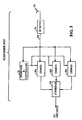
- FIG. 3 is a block diagram of the receive processing portion of subscriber unit 20 when configured in accordance with one embodiment of the invention.
- Antenna system 70 is coupled to RF receiver 74 , which is in turn coupled to demodulators 80a - c and to searcher and controller 78 .
- Demodulators 80a - c are also coupled to searcher and controller 78 , as well as to combiner 82 . While three demodulators 80 are shown, the use of other numbers of demodulators including four or more is consistent with the use of the present invention.
- antenna system 70 receives the left slant and right slant RF signals from base station 22 .
- the RF receiver filters, down converts and digitizes those signals generating samples 86 .
- Searcher and control system 78 receives samples 86 and performs repeated time offset searches using + the PN codes used to modulate the signals, to determine the arrival times of the signals 60 , 60a , 62 and 62a of FIG 2 .
- searcher and control system 78 configures demodulators 80a - c to process a signal 60 , 60a , 62 and 62a within either right slant samples 86 or left slant samples 86 at the associated arrival time using a control interface.
- demodulators 80a - c demodulate the samples using a PN spreading code and a Walsh channel code configured and generated in accordance with the IS-95 standard and the associated arrival time (offset). Additionally, demodulators 80a - c perform time tracking to adjust for changes in the arrival time. The demodulation performed by demodulators 80a - c generates soft decision data received by combiner 82 . Combiner 82 combines the soft decision data yielding summed soft decision data which is received by a decoder (not shown). The decoder performs soft decision decoding to generate hard decision data which is then made available for further processing such as data manipulation or regeneration of audio tones. Various types of decoding are known and may be incorporated into the present invention including trellis or Viterbi decoding.
- antenna system 70 will have a polarization reception characteristic due to its shape and orientation that will separate signals having different polarizations. As the orientation changes, the nature of the polarization reception will change as well providing signal diversity over time. This improves processing performance of subscriber unit 20 and thus enhances the call processing capability of an associated cellular telephone system. This enhanced call processing capability is typically used to increase the number of telephone calls that can be conducted at any given instant.
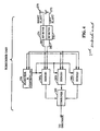
- FIG. 4 is a block diagram of the receive processing portion of subscriber unit 20 when configured in accordance with another embodiment of the invention.
- Right slant antenna system 270 and left slant antenna system 272 receive RF signals that are provided to RF receivers 274 and 276 .
- RF receivers 274 and 276 are coupled to demodulators 280a - c and to searcher and controller 278 .
- Demodulators 280a - c are coupled to searcher and controller 278 and to combiner 282 . While three demodulators 280 are shown, the use of other numbers of demodulators including four or more is consistent with the use of the present invention. While referred to as right slant and left slant antenna systems 270 and 272 , the typical mobility of the subscriber unit will alter the absolute polarity of the antenna systems, but not the relative polarity.
- right slant antenna system 270 receives signals with a right slant polarity and receiver 274 frequency filters, down converts and digitizes those signals generating right slant samples 286 .
- left slant antenna system 272 performs polarized filtration of the RF signals, and receiver 276 frequency filters, down converts and digitizes those signals generating left slant samples 288 .
- Various methods and antennas for performing polarized reception are well known in the art.
- right slant samples 286 contain only those signals that having a right slant component, and therefore the interference due to orthogonally polarized signals is removed.
- left slant samples 288 contain only those signals having a left slant component, and therefore the interference from other orthogonally polarized signals is removed.
- Searcher 278 receives right slant samples 286 and left slant samples 288 and performs repeated time offset searches using the PN codes used to modulate the signals, to determine the arrival times of the signals 60 , 60a , 62 and 62a of FIG 2. Once the arrival times of signals 60 , 60a , 62 and 62a are determined, searcher 278 configures demodulators 280a - c to process a signal 60 , 60a , 62 and 62a within either right slant samples 286 or left slant samples 288 at the associated arrival time using a control interface.
- demodulators 280a - c demodulate the samples using a PN spreading code and a Walsh channel code configured and generated in accordance with the IS-95 standard and the associated arrival time (offset). Additionally, demodulators 280a - c perform time tracking to adjust for changes in the arrival time.
- demodulation performed by demodulators 280a - c generates soft decision data received by combiner 282 .
- Combiner 282 combines the soft decision data yielding summed soft decision data which is received by a decoder (not shown).
- the decoder performs soft decision decoding to generate hard decision data which is then made available for further processing such as data manipulation or regeneration of audio tones.
- Various types of decoding are known and may be incorporated into the present invention including trellis or Viterbi decoding.
- the various signals received can be isolated from one another before demodulation and therefore the degree to which they interfere with one another is reduced. Additionally, by using two antennas with different polarizations, the best available signal can be received, identified and processed independently, thus enhancing the average signal quality. This improves processing performance of subscriber unit 20 , and thus enhances the call processing capability of an associated cellular telephone system. This enhanced call processing capability is typically used to increase the number of telephone calls that can be conducted at any given instant.
- FIG. 5 is a highly simplified block diagram of a portion of a cellular telephone system configured in accordance with another embodiment of the invention.
- Base stations 22 are coupled to base station controller 24 , which is in turn coupled to the public switch telephone network (PSTN).
- PSTN is the conventional wireline telephone network.
- subscriber unit 20 is transmitting an RF signal to a base station 22 in order to conduct communications.
- Subscriber unit 20 generates two orthogonally polarized forward link signals referred to as right slant signal 360a and left slant signal 360b transmitted from antenna systems 362 and 364 . These signals are generated by two separate antennas which are part of subscriber unit 20 in response to digital signals received from digital unit 365 . The data is received from some external source such as a digitized voice.
- Delay 350 is coupled to RF unit 352b .
- Delay 350 introduces a delay into the outbound right slant signal 360a in order to provide time diversity.
- the duration of the delay is at least as long as the duration of one bit, or "chip,” from the PN codes used for modulation and demodulation, and preferably equal to the duration of 2-3 chips.
- right slant signal 360a and left slant signal 360b are transmitted with different directional orientations.
- antenna 364 may be pointed in a slightly different direction than antenna 362 .
- the difference in the directional orientations should be slight so that the two signals are received at the same location while experiencing different multipath conditions. This enhances the diversity of signal source.
- the right slant signal 360a from antenna 364 is reflected by tree 61 generating multipath signal 362a and the left slant signal 360b from antenna 362 is reflected by building 63 generating multipath signal 362b .
- reflection can modify an already polarized signal, or add polarization to a non-polarized signal.
- Base station 22 receives signals 360a , 360b , 362a and 362b and performs receive demodulation to extract the data transmitted.
- base station 22 receives signals 360a , 360b , 362a and 362b via an antenna system with a particular polarization which filters some of the resulting multipath.
- FIG. 6 is a block diagram of a portion of the receive processing system of a base station 22 when configured to communicate with a subscriber unit 20 , in accordance with still another exemplary embodiment of the invention.
- a cell site modem (CSM) 84 is shown coupled to an antenna system.
- the antenna system is comprised of right slant antenna 170 and left slant antenna 172 as well as RF receivers 174 and 176 .
- the base station receives a set of signals such as signals 360a , 360b , 362a and 362b of FIG. 5.
- the base station receives three instances, or occurrences, of the RF signal transmitted from subscriber unit 20 .
- One instance 360a or 360b is received via a direct path.
- Another instance 362a is reflected from tree 61 .
- the third instance 362b is reflected from building 63 .
- other signals are transmitted from other subscriber units 20 and received by antennas 170 and 72 .
- CSM cell site modem
- searcher and controller 178 receives the digitized signals and identifies multipath instances of the signal being processed by applying the associated spreading codes at various time offsets. Additionally, searcher and controller 178 examines the input from antenna 170 and antenna 172 separately and determines which is producing the best result for a particular finger. Once multipath signals are identified, searcher and controller 178 assigns a demodulator 180 to process that multipath signal from the particular antenna determined to provide the best result. The resulting soft decision data from demodulators 180a - c are combined by combiner 182 and passed to a trellis or Viterbi decoder and then on to the BSC.
- the present invention enhances the receive processing at the receive system of the multipath signals received from a particular subscriber unit 20 .
- reflection and other phenomenoa that cause multipath transmission often alter polarization of the signal, including the introduction of non-uniform polarization.
- differently polarized multipath instances of the signals are filtered from one another, and therefore do not interfere with one another.
- the introduction of delay further prevents interference by decreasing the likelihood that the signals will combined destructively and therefore cause a fade condition.
- the present invention is a novel and improved method and apparatus for transmitting and receiving code division multiple access (CDMA) signals.
- CDMA code division multiple access
Landscapes
- Engineering & Computer Science (AREA)
- Computer Networks & Wireless Communication (AREA)
- Signal Processing (AREA)
- Mobile Radio Communication Systems (AREA)
- Radio Transmission System (AREA)
- Input Circuits Of Receivers And Coupling Of Receivers And Audio Equipment (AREA)
- Telephone Function (AREA)
- Time-Division Multiplex Systems (AREA)
- Optical Communication System (AREA)
- Special Wing (AREA)
Applications Claiming Priority (3)
| Application Number | Priority Date | Filing Date | Title |
|---|---|---|---|
| US941147 | 1997-09-30 | ||
| US08/941,147 US6061336A (en) | 1997-09-30 | 1997-09-30 | Polarization enhanced CDMA communication system |
| PCT/US1998/020348 WO1999017467A1 (en) | 1997-09-30 | 1998-09-29 | Polarization enhanced cdma communication system |
Publications (2)
| Publication Number | Publication Date |
|---|---|
| EP1021872A1 EP1021872A1 (en) | 2000-07-26 |
| EP1021872B1 true EP1021872B1 (en) | 2004-04-14 |
Family
ID=25476002
Family Applications (1)
| Application Number | Title | Priority Date | Filing Date |
|---|---|---|---|
| EP98949598A Expired - Lifetime EP1021872B1 (en) | 1997-09-30 | 1998-09-29 | Polarization enhanced cdma communication system |
Country Status (9)
| Country | Link |
|---|---|
| US (1) | US6061336A (enExample) |
| EP (1) | EP1021872B1 (enExample) |
| JP (1) | JP2001518737A (enExample) |
| KR (1) | KR100738268B1 (enExample) |
| CN (1) | CN1123992C (enExample) |
| AT (1) | ATE264577T1 (enExample) |
| AU (1) | AU9589098A (enExample) |
| DE (1) | DE69823219T2 (enExample) |
| WO (1) | WO1999017467A1 (enExample) |
Families Citing this family (11)
| Publication number | Priority date | Publication date | Assignee | Title |
|---|---|---|---|---|
| JP3967452B2 (ja) * | 1998-03-13 | 2007-08-29 | 株式会社東芝 | スペクトラム拡散無線伝送受信装置 |
| US6304216B1 (en) * | 1999-03-30 | 2001-10-16 | Conexant Systems, Inc. | Signal detector employing correlation analysis of non-uniform and disjoint sample segments |
| JP2000358016A (ja) * | 1999-06-15 | 2000-12-26 | Mitsubishi Electric Corp | 復調器および通信システム |
| AU2001237971A1 (en) * | 2000-01-26 | 2001-08-07 | Vyyo, Ltd. | Space diversity method and system for broadband wireless access |
| US6671340B1 (en) * | 2000-06-15 | 2003-12-30 | Ibiquity Digital Corporation | Method and apparatus for reduction of interference in FM in-band on-channel digital audio broadcasting receivers |
| EP1354417A1 (en) * | 2001-01-23 | 2003-10-22 | Jyoti Prasad | A polarization division multiplex access system |
| DE10248409A1 (de) | 2002-10-17 | 2004-04-29 | Philips Intellectual Property & Standards Gmbh | Verfahren zur Steuerung der Programmauswahl am Empfangsgerät eines Broadcast-Mediums |
| US7181220B2 (en) * | 2003-09-24 | 2007-02-20 | Intel Corporation | Seamless roaming apparatus, systems, and methods |
| JP4241648B2 (ja) * | 2005-03-10 | 2009-03-18 | ソニー株式会社 | 無線通信システムと送信装置と受信装置および無線通信方法 |
| US8619671B2 (en) * | 2008-02-27 | 2013-12-31 | Electronics And Telecommuniations Research Institute | Transmission reception apparatus of data using polarization transmission in los radio communication system |
| US8391334B1 (en) * | 2010-09-27 | 2013-03-05 | L-3 Communications Corp | Communications reliability in a hub-spoke communications system |
Family Cites Families (18)
| Publication number | Priority date | Publication date | Assignee | Title |
|---|---|---|---|---|
| JPS58197929A (ja) * | 1982-05-14 | 1983-11-17 | Nec Corp | ダイバ−シチ通信方式 |
| JPS60100840A (ja) * | 1983-11-07 | 1985-06-04 | Nippon Telegr & Teleph Corp <Ntt> | 携帯無線機用ダイバ−シチ受信機 |
| JPS6239930A (ja) * | 1985-08-14 | 1987-02-20 | Fumio Ikegami | デイジタル通信装置 |
| US4901307A (en) * | 1986-10-17 | 1990-02-13 | Qualcomm, Inc. | Spread spectrum multiple access communication system using satellite or terrestrial repeaters |
| US5513176A (en) * | 1990-12-07 | 1996-04-30 | Qualcomm Incorporated | Dual distributed antenna system |
| DE69432844T2 (de) * | 1993-04-29 | 2004-05-19 | Ericsson Inc. | Zeitdiversityübertragungssystem zum Herabsetzung der Nachbarkanalstörung in Mobiltelefonsystemen |
| US5832389A (en) * | 1994-03-24 | 1998-11-03 | Ericsson Inc. | Wideband digitization systems and methods for cellular radiotelephones |
| US5581707A (en) * | 1994-07-27 | 1996-12-03 | Psc, Inc. | System for wireless collection of data from a plurality of remote data collection units such as portable bar code readers |
| US6006069A (en) * | 1994-11-28 | 1999-12-21 | Bosch Telecom Gmbh | Point-to-multipoint communications system |
| FR2729025B1 (fr) * | 1995-01-02 | 1997-03-21 | Europ Agence Spatiale | Procede et systeme de transmission de signaux radioelectriques via un reseau de satellites entre une station terrestre fixe et des terminaux mobiles d'usagers |
| US5654979A (en) * | 1995-01-13 | 1997-08-05 | Qualcomm Incorporated | Cell site demodulation architecture for a spread spectrum multiple access communication systems |
| US5659353A (en) * | 1995-03-17 | 1997-08-19 | Bell Atlantic Network Services, Inc. | Television distribution system and method |
| US5649287A (en) * | 1995-03-29 | 1997-07-15 | Telefonaktiebolaget Lm Ericsson | Orthogonalizing methods for antenna pattern nullfilling |
| FI105512B (fi) * | 1995-05-24 | 2000-08-31 | Nokia Networks Oy | Menetelmä kulmatoisteen aikaansaamiseksi sekä tukiasemalaitteisto |
| JPH08321799A (ja) * | 1995-05-25 | 1996-12-03 | Nippondenso Co Ltd | 無線通信装置及び通信システム |
| US5764696A (en) * | 1995-06-02 | 1998-06-09 | Time Domain Corporation | Chiral and dual polarization techniques for an ultra-wide band communication system |
| FI110645B (fi) * | 1995-06-30 | 2003-02-28 | Nokia Corp | Vastaanottomenetelmä ja tukiasemavastaanotin |
| KR20050098028A (ko) * | 1997-03-03 | 2005-10-10 | 셀레트라 리미티드 | 통신 개선 방법 및 시스템 |
-
1997
- 1997-09-30 US US08/941,147 patent/US6061336A/en not_active Expired - Lifetime
-
1998
- 1998-09-29 KR KR1020007003313A patent/KR100738268B1/ko not_active Expired - Fee Related
- 1998-09-29 EP EP98949598A patent/EP1021872B1/en not_active Expired - Lifetime
- 1998-09-29 AU AU95890/98A patent/AU9589098A/en not_active Abandoned
- 1998-09-29 JP JP2000514412A patent/JP2001518737A/ja active Pending
- 1998-09-29 DE DE69823219T patent/DE69823219T2/de not_active Expired - Lifetime
- 1998-09-29 WO PCT/US1998/020348 patent/WO1999017467A1/en not_active Ceased
- 1998-09-29 AT AT98949598T patent/ATE264577T1/de not_active IP Right Cessation
- 1998-09-29 CN CN98809571A patent/CN1123992C/zh not_active Expired - Lifetime
Also Published As
| Publication number | Publication date |
|---|---|
| WO1999017467A1 (en) | 1999-04-08 |
| US6061336A (en) | 2000-05-09 |
| DE69823219D1 (de) | 2004-05-19 |
| AU9589098A (en) | 1999-04-23 |
| CN1271479A (zh) | 2000-10-25 |
| EP1021872A1 (en) | 2000-07-26 |
| KR20010030757A (ko) | 2001-04-16 |
| JP2001518737A (ja) | 2001-10-16 |
| ATE264577T1 (de) | 2004-04-15 |
| CN1123992C (zh) | 2003-10-08 |
| HK1029876A1 (en) | 2001-04-12 |
| KR100738268B1 (ko) | 2007-07-12 |
| DE69823219T2 (de) | 2005-05-25 |
Similar Documents
| Publication | Publication Date | Title |
|---|---|---|
| CN1074872C (zh) | 数字通信系统 | |
| US7653149B2 (en) | Dynamic sectorization in a spread spectrum communication system | |
| US6345188B1 (en) | Base station for phasing a transmission signal to a mobile unit based on information recieved from the mobile unit | |
| US5987016A (en) | Method and apparatus for tracking a communication signal in a wireless communication system | |
| FI120282B (fi) | Lineaarisen peittoalueen antennijärjestelmä CDMA-tietoliikennejärjestelmää varten | |
| EP0872039B1 (en) | Method for providing angular diversity, and base station equipment | |
| AU1469397A (en) | Method and apparatus for providing antenna diversity in a portable radiotelephone | |
| US6754253B2 (en) | Receiver architecture for transmit diversity in CDMA system | |
| US7020112B2 (en) | System and method for combining signals at multiple base station receivers | |
| JP2002525905A (ja) | レーキ受信器 | |
| WO1996042119A1 (en) | Narrow beam antenna systems with angular diversity | |
| EP0772919A1 (en) | Method for transmitting pilot channels, and a cellular radio system | |
| EP1021872B1 (en) | Polarization enhanced cdma communication system | |
| US6799026B1 (en) | Handset diversity in wireless communications system | |
| US6275482B1 (en) | Combined angular, spatial, and temporal diversity for mobile radio system | |
| AU728418B2 (en) | Method for allocating rake branches and rake receiver | |
| US20040196805A1 (en) | Combined selective time switching transmission deversity (ststd) method and system | |
| EP1063781A1 (en) | Method of finding the best transmission channels for a CDMA signal, and components therefor | |
| HK1029876B (en) | Method for transmitting and receiving code division multiple access signals and system using the transmitting method | |
| MXPA98005208A (en) | Method and apparatus for providing an antenna endlessity in a radiotelefono porta | |
| WO1996042120A1 (en) | Multiple narrow beam antenna transmission systems | |
| HK1100148A (en) | Linear coverage area antenna system for a cdma communication system |
Legal Events
| Date | Code | Title | Description |
|---|---|---|---|
| PUAI | Public reference made under article 153(3) epc to a published international application that has entered the european phase |
Free format text: ORIGINAL CODE: 0009012 |
|
| 17P | Request for examination filed |
Effective date: 20000313 |
|
| AK | Designated contracting states |
Kind code of ref document: A1 Designated state(s): AT BE CH CY DE DK ES FI FR GB GR IE IT LI LU MC NL PT SE |
|
| AX | Request for extension of the european patent |
Free format text: AL PAYMENT 20000313;LT PAYMENT 20000313;LV PAYMENT 20000313;MK PAYMENT 20000313;RO PAYMENT 20000313;SI PAYMENT 20000313 |
|
| 17Q | First examination report despatched |
Effective date: 20011123 |
|
| GRAP | Despatch of communication of intention to grant a patent |
Free format text: ORIGINAL CODE: EPIDOSNIGR1 |
|
| GRAS | Grant fee paid |
Free format text: ORIGINAL CODE: EPIDOSNIGR3 |
|
| GRAA | (expected) grant |
Free format text: ORIGINAL CODE: 0009210 |
|
| AK | Designated contracting states |
Kind code of ref document: B1 Designated state(s): AT BE CH CY DE DK ES FI FR GB GR IE IT LI LU MC NL PT SE |
|
| AX | Request for extension of the european patent |
Extension state: AL LT LV MK RO SI |
|
| PG25 | Lapsed in a contracting state [announced via postgrant information from national office to epo] |
Ref country code: NL Free format text: LAPSE BECAUSE OF FAILURE TO SUBMIT A TRANSLATION OF THE DESCRIPTION OR TO PAY THE FEE WITHIN THE PRESCRIBED TIME-LIMIT Effective date: 20040414 Ref country code: LI Free format text: LAPSE BECAUSE OF FAILURE TO SUBMIT A TRANSLATION OF THE DESCRIPTION OR TO PAY THE FEE WITHIN THE PRESCRIBED TIME-LIMIT Effective date: 20040414 Ref country code: CY Free format text: LAPSE BECAUSE OF FAILURE TO SUBMIT A TRANSLATION OF THE DESCRIPTION OR TO PAY THE FEE WITHIN THE PRESCRIBED TIME-LIMIT Effective date: 20040414 Ref country code: CH Free format text: LAPSE BECAUSE OF FAILURE TO SUBMIT A TRANSLATION OF THE DESCRIPTION OR TO PAY THE FEE WITHIN THE PRESCRIBED TIME-LIMIT Effective date: 20040414 Ref country code: BE Free format text: LAPSE BECAUSE OF FAILURE TO SUBMIT A TRANSLATION OF THE DESCRIPTION OR TO PAY THE FEE WITHIN THE PRESCRIBED TIME-LIMIT Effective date: 20040414 Ref country code: AT Free format text: LAPSE BECAUSE OF FAILURE TO SUBMIT A TRANSLATION OF THE DESCRIPTION OR TO PAY THE FEE WITHIN THE PRESCRIBED TIME-LIMIT Effective date: 20040414 |
|
| REG | Reference to a national code |
Ref country code: GB Ref legal event code: FG4D |
|
| REG | Reference to a national code |
Ref country code: CH Ref legal event code: EP |
|
| REF | Corresponds to: |
Ref document number: 69823219 Country of ref document: DE Date of ref document: 20040519 Kind code of ref document: P |
|
| REG | Reference to a national code |
Ref country code: IE Ref legal event code: FG4D |
|
| PG25 | Lapsed in a contracting state [announced via postgrant information from national office to epo] |
Ref country code: SE Free format text: LAPSE BECAUSE OF FAILURE TO SUBMIT A TRANSLATION OF THE DESCRIPTION OR TO PAY THE FEE WITHIN THE PRESCRIBED TIME-LIMIT Effective date: 20040714 Ref country code: GR Free format text: LAPSE BECAUSE OF FAILURE TO SUBMIT A TRANSLATION OF THE DESCRIPTION OR TO PAY THE FEE WITHIN THE PRESCRIBED TIME-LIMIT Effective date: 20040714 Ref country code: DK Free format text: LAPSE BECAUSE OF FAILURE TO SUBMIT A TRANSLATION OF THE DESCRIPTION OR TO PAY THE FEE WITHIN THE PRESCRIBED TIME-LIMIT Effective date: 20040714 |
|
| PG25 | Lapsed in a contracting state [announced via postgrant information from national office to epo] |
Ref country code: ES Free format text: LAPSE BECAUSE OF FAILURE TO SUBMIT A TRANSLATION OF THE DESCRIPTION OR TO PAY THE FEE WITHIN THE PRESCRIBED TIME-LIMIT Effective date: 20040725 |
|
| LTIE | Lt: invalidation of european patent or patent extension |
Effective date: 20040414 |
|
| PG25 | Lapsed in a contracting state [announced via postgrant information from national office to epo] |
Ref country code: LU Free format text: LAPSE BECAUSE OF NON-PAYMENT OF DUE FEES Effective date: 20040929 Ref country code: IE Free format text: LAPSE BECAUSE OF NON-PAYMENT OF DUE FEES Effective date: 20040929 |
|
| PG25 | Lapsed in a contracting state [announced via postgrant information from national office to epo] |
Ref country code: MC Free format text: LAPSE BECAUSE OF NON-PAYMENT OF DUE FEES Effective date: 20040930 |
|
| NLV1 | Nl: lapsed or annulled due to failure to fulfill the requirements of art. 29p and 29m of the patents act | ||
| REG | Reference to a national code |
Ref country code: CH Ref legal event code: PL |
|
| ET | Fr: translation filed | ||
| PLBQ | Unpublished change to opponent data |
Free format text: ORIGINAL CODE: EPIDOS OPPO |
|
| PLBI | Opposition filed |
Free format text: ORIGINAL CODE: 0009260 |
|
| PLAQ | Examination of admissibility of opposition: information related to despatch of communication + time limit deleted |
Free format text: ORIGINAL CODE: EPIDOSDOPE2 |
|
| PLAR | Examination of admissibility of opposition: information related to receipt of reply deleted |
Free format text: ORIGINAL CODE: EPIDOSDOPE4 |
|
| PLAX | Notice of opposition and request to file observation + time limit sent |
Free format text: ORIGINAL CODE: EPIDOSNOBS2 |
|
| PLBQ | Unpublished change to opponent data |
Free format text: ORIGINAL CODE: EPIDOS OPPO |
|
| PLAB | Opposition data, opponent's data or that of the opponent's representative modified |
Free format text: ORIGINAL CODE: 0009299OPPO |
|
| 26 | Opposition filed |
Opponent name: NOKIA CORPORATION Effective date: 20050114 |
|
| R26 | Opposition filed (corrected) |
Opponent name: NOKIA CORPORATION Effective date: 20050114 |
|
| REG | Reference to a national code |
Ref country code: IE Ref legal event code: MM4A |
|
| REG | Reference to a national code |
Ref country code: FR Ref legal event code: ST |
|
| PLAF | Information modified related to communication of a notice of opposition and request to file observations + time limit |
Free format text: ORIGINAL CODE: EPIDOSCOBS2 |
|
| PLAF | Information modified related to communication of a notice of opposition and request to file observations + time limit |
Free format text: ORIGINAL CODE: EPIDOSCOBS2 |
|
| REG | Reference to a national code |
Ref country code: FR Ref legal event code: RN Ref country code: FR Ref legal event code: FC |
|
| PLAF | Information modified related to communication of a notice of opposition and request to file observations + time limit |
Free format text: ORIGINAL CODE: EPIDOSCOBS2 |
|
| PLAF | Information modified related to communication of a notice of opposition and request to file observations + time limit |
Free format text: ORIGINAL CODE: EPIDOSCOBS2 |
|
| PLBB | Reply of patent proprietor to notice(s) of opposition received |
Free format text: ORIGINAL CODE: EPIDOSNOBS3 |
|
| REG | Reference to a national code |
Ref country code: HK Ref legal event code: WD Ref document number: 1030842 Country of ref document: HK |
|
| PG25 | Lapsed in a contracting state [announced via postgrant information from national office to epo] |
Ref country code: PT Free format text: LAPSE BECAUSE OF NON-PAYMENT OF DUE FEES Effective date: 20040914 |
|
| PLBD | Termination of opposition procedure: decision despatched |
Free format text: ORIGINAL CODE: EPIDOSNOPC1 |
|
| PLBP | Opposition withdrawn |
Free format text: ORIGINAL CODE: 0009264 |
|
| PLBM | Termination of opposition procedure: date of legal effect published |
Free format text: ORIGINAL CODE: 0009276 |
|
| STAA | Information on the status of an ep patent application or granted ep patent |
Free format text: STATUS: OPPOSITION PROCEDURE CLOSED |
|
| 27C | Opposition proceedings terminated |
Effective date: 20081003 |
|
| PGFP | Annual fee paid to national office [announced via postgrant information from national office to epo] |
Ref country code: IT Payment date: 20100918 Year of fee payment: 13 Ref country code: FR Payment date: 20100920 Year of fee payment: 13 Ref country code: FI Payment date: 20100901 Year of fee payment: 13 |
|
| PG25 | Lapsed in a contracting state [announced via postgrant information from national office to epo] |
Ref country code: FI Free format text: LAPSE BECAUSE OF NON-PAYMENT OF DUE FEES Effective date: 20110929 Ref country code: IT Free format text: LAPSE BECAUSE OF NON-PAYMENT OF DUE FEES Effective date: 20110929 |
|
| REG | Reference to a national code |
Ref country code: FR Ref legal event code: ST Effective date: 20120531 |
|
| PG25 | Lapsed in a contracting state [announced via postgrant information from national office to epo] |
Ref country code: FR Free format text: LAPSE BECAUSE OF NON-PAYMENT OF DUE FEES Effective date: 20110930 |
|
| PGFP | Annual fee paid to national office [announced via postgrant information from national office to epo] |
Ref country code: DE Payment date: 20170711 Year of fee payment: 20 Ref country code: GB Payment date: 20170829 Year of fee payment: 20 |
|
| REG | Reference to a national code |
Ref country code: DE Ref legal event code: R071 Ref document number: 69823219 Country of ref document: DE |
|
| REG | Reference to a national code |
Ref country code: GB Ref legal event code: PE20 Expiry date: 20180928 |
|
| PG25 | Lapsed in a contracting state [announced via postgrant information from national office to epo] |
Ref country code: GB Free format text: LAPSE BECAUSE OF EXPIRATION OF PROTECTION Effective date: 20180928 |