EP1020859B1 - Optical storage medium - Google Patents
Optical storage medium Download PDFInfo
- Publication number
- EP1020859B1 EP1020859B1 EP00300074A EP00300074A EP1020859B1 EP 1020859 B1 EP1020859 B1 EP 1020859B1 EP 00300074 A EP00300074 A EP 00300074A EP 00300074 A EP00300074 A EP 00300074A EP 1020859 B1 EP1020859 B1 EP 1020859B1
- Authority
- EP
- European Patent Office
- Prior art keywords
- bit
- data
- write
- disc
- edit
- Prior art date
- Legal status (The legal status is an assumption and is not a legal conclusion. Google has not performed a legal analysis and makes no representation as to the accuracy of the status listed.)
- Expired - Lifetime
Links
- 230000003287 optical effect Effects 0.000 title claims description 20
- 238000000034 method Methods 0.000 claims description 13
- 230000007704 transition Effects 0.000 claims description 9
- 238000001514 detection method Methods 0.000 description 4
- 238000011084 recovery Methods 0.000 description 3
- 238000012937 correction Methods 0.000 description 2
- 238000000137 annealing Methods 0.000 description 1
- 238000013500 data storage Methods 0.000 description 1
- 238000007429 general method Methods 0.000 description 1
- 239000000463 material Substances 0.000 description 1
- 239000012782 phase change material Substances 0.000 description 1
- 238000012545 processing Methods 0.000 description 1
- 238000002310 reflectometry Methods 0.000 description 1
- 239000000758 substrate Substances 0.000 description 1
- 230000009897 systematic effect Effects 0.000 description 1
Images


Classifications
-
- G—PHYSICS
- G11—INFORMATION STORAGE
- G11B—INFORMATION STORAGE BASED ON RELATIVE MOVEMENT BETWEEN RECORD CARRIER AND TRANSDUCER
- G11B7/00—Recording or reproducing by optical means, e.g. recording using a thermal beam of optical radiation by modifying optical properties or the physical structure, reproducing using an optical beam at lower power by sensing optical properties; Record carriers therefor
- G11B7/007—Arrangement of the information on the record carrier, e.g. form of tracks, actual track shape, e.g. wobbled, or cross-section, e.g. v-shaped; Sequential information structures, e.g. sectoring or header formats within a track
- G11B7/00745—Sectoring or header formats within a track
-
- G—PHYSICS
- G11—INFORMATION STORAGE
- G11B—INFORMATION STORAGE BASED ON RELATIVE MOVEMENT BETWEEN RECORD CARRIER AND TRANSDUCER
- G11B20/00—Signal processing not specific to the method of recording or reproducing; Circuits therefor
- G11B20/10—Digital recording or reproducing
- G11B20/12—Formatting, e.g. arrangement of data block or words on the record carriers
- G11B20/1217—Formatting, e.g. arrangement of data block or words on the record carriers on discs
- G11B20/1251—Formatting, e.g. arrangement of data block or words on the record carriers on discs for continuous data, e.g. digitised analog information signals, pulse code modulated [PCM] data
-
- G—PHYSICS
- G11—INFORMATION STORAGE
- G11B—INFORMATION STORAGE BASED ON RELATIVE MOVEMENT BETWEEN RECORD CARRIER AND TRANSDUCER
- G11B27/00—Editing; Indexing; Addressing; Timing or synchronising; Monitoring; Measuring tape travel
- G11B27/02—Editing, e.g. varying the order of information signals recorded on, or reproduced from, record carriers
- G11B27/031—Electronic editing of digitised analogue information signals, e.g. audio or video signals
- G11B27/036—Insert-editing
-
- G—PHYSICS
- G11—INFORMATION STORAGE
- G11B—INFORMATION STORAGE BASED ON RELATIVE MOVEMENT BETWEEN RECORD CARRIER AND TRANSDUCER
- G11B27/00—Editing; Indexing; Addressing; Timing or synchronising; Monitoring; Measuring tape travel
- G11B27/10—Indexing; Addressing; Timing or synchronising; Measuring tape travel
- G11B27/19—Indexing; Addressing; Timing or synchronising; Measuring tape travel by using information detectable on the record carrier
- G11B27/28—Indexing; Addressing; Timing or synchronising; Measuring tape travel by using information detectable on the record carrier by using information signals recorded by the same method as the main recording
- G11B27/30—Indexing; Addressing; Timing or synchronising; Measuring tape travel by using information detectable on the record carrier by using information signals recorded by the same method as the main recording on the same track as the main recording
- G11B27/3027—Indexing; Addressing; Timing or synchronising; Measuring tape travel by using information detectable on the record carrier by using information signals recorded by the same method as the main recording on the same track as the main recording used signal is digitally coded
-
- G—PHYSICS
- G11—INFORMATION STORAGE
- G11B—INFORMATION STORAGE BASED ON RELATIVE MOVEMENT BETWEEN RECORD CARRIER AND TRANSDUCER
- G11B20/00—Signal processing not specific to the method of recording or reproducing; Circuits therefor
- G11B20/10—Digital recording or reproducing
- G11B20/14—Digital recording or reproducing using self-clocking codes
- G11B20/1403—Digital recording or reproducing using self-clocking codes characterised by the use of two levels
- G11B20/1423—Code representation depending on subsequent bits, e.g. delay modulation, double density code, Miller code
-
- G—PHYSICS
- G11—INFORMATION STORAGE
- G11B—INFORMATION STORAGE BASED ON RELATIVE MOVEMENT BETWEEN RECORD CARRIER AND TRANSDUCER
- G11B20/00—Signal processing not specific to the method of recording or reproducing; Circuits therefor
- G11B20/10—Digital recording or reproducing
- G11B20/18—Error detection or correction; Testing, e.g. of drop-outs
-
- G—PHYSICS
- G11—INFORMATION STORAGE
- G11B—INFORMATION STORAGE BASED ON RELATIVE MOVEMENT BETWEEN RECORD CARRIER AND TRANSDUCER
- G11B20/00—Signal processing not specific to the method of recording or reproducing; Circuits therefor
- G11B20/10—Digital recording or reproducing
- G11B20/12—Formatting, e.g. arrangement of data block or words on the record carriers
- G11B2020/1264—Formatting, e.g. arrangement of data block or words on the record carriers wherein the formatting concerns a specific kind of data
- G11B2020/1265—Control data, system data or management information, i.e. data used to access or process user data
- G11B2020/1267—Address data
- G11B2020/1268—Address in pregroove [ADIP] information
-
- G—PHYSICS
- G11—INFORMATION STORAGE
- G11B—INFORMATION STORAGE BASED ON RELATIVE MOVEMENT BETWEEN RECORD CARRIER AND TRANSDUCER
- G11B20/00—Signal processing not specific to the method of recording or reproducing; Circuits therefor
- G11B20/10—Digital recording or reproducing
- G11B20/12—Formatting, e.g. arrangement of data block or words on the record carriers
- G11B2020/1264—Formatting, e.g. arrangement of data block or words on the record carriers wherein the formatting concerns a specific kind of data
- G11B2020/1265—Control data, system data or management information, i.e. data used to access or process user data
- G11B2020/1277—Control data, system data or management information, i.e. data used to access or process user data for managing gaps between two recordings, e.g. control data in linking areas, run-in or run-out fields, guard or buffer zones
-
- G—PHYSICS
- G11—INFORMATION STORAGE
- G11B—INFORMATION STORAGE BASED ON RELATIVE MOVEMENT BETWEEN RECORD CARRIER AND TRANSDUCER
- G11B20/00—Signal processing not specific to the method of recording or reproducing; Circuits therefor
- G11B20/10—Digital recording or reproducing
- G11B20/12—Formatting, e.g. arrangement of data block or words on the record carriers
- G11B2020/1264—Formatting, e.g. arrangement of data block or words on the record carriers wherein the formatting concerns a specific kind of data
- G11B2020/1265—Control data, system data or management information, i.e. data used to access or process user data
- G11B2020/1287—Synchronisation pattern, e.g. VCO fields
-
- G—PHYSICS
- G11—INFORMATION STORAGE
- G11B—INFORMATION STORAGE BASED ON RELATIVE MOVEMENT BETWEEN RECORD CARRIER AND TRANSDUCER
- G11B20/00—Signal processing not specific to the method of recording or reproducing; Circuits therefor
- G11B20/10—Digital recording or reproducing
- G11B20/12—Formatting, e.g. arrangement of data block or words on the record carriers
- G11B2020/1291—Formatting, e.g. arrangement of data block or words on the record carriers wherein the formatting serves a specific purpose
- G11B2020/1292—Enhancement of the total storage capacity
-
- G—PHYSICS
- G11—INFORMATION STORAGE
- G11B—INFORMATION STORAGE BASED ON RELATIVE MOVEMENT BETWEEN RECORD CARRIER AND TRANSDUCER
- G11B2220/00—Record carriers by type
- G11B2220/20—Disc-shaped record carriers
- G11B2220/21—Disc-shaped record carriers characterised in that the disc is of read-only, rewritable, or recordable type
- G11B2220/215—Recordable discs
- G11B2220/216—Rewritable discs
-
- G—PHYSICS
- G11—INFORMATION STORAGE
- G11B—INFORMATION STORAGE BASED ON RELATIVE MOVEMENT BETWEEN RECORD CARRIER AND TRANSDUCER
- G11B2220/00—Record carriers by type
- G11B2220/20—Disc-shaped record carriers
- G11B2220/25—Disc-shaped record carriers characterised in that the disc is based on a specific recording technology
- G11B2220/2537—Optical discs
- G11B2220/2545—CDs
-
- G—PHYSICS
- G11—INFORMATION STORAGE
- G11B—INFORMATION STORAGE BASED ON RELATIVE MOVEMENT BETWEEN RECORD CARRIER AND TRANSDUCER
- G11B2220/00—Record carriers by type
- G11B2220/20—Disc-shaped record carriers
- G11B2220/25—Disc-shaped record carriers characterised in that the disc is based on a specific recording technology
- G11B2220/2537—Optical discs
- G11B2220/2562—DVDs [digital versatile discs]; Digital video discs; MMCDs; HDCDs
- G11B2220/257—DVDs belonging to the plus family, i.e. +R, +RW, +VR
-
- G—PHYSICS
- G11—INFORMATION STORAGE
- G11B—INFORMATION STORAGE BASED ON RELATIVE MOVEMENT BETWEEN RECORD CARRIER AND TRANSDUCER
- G11B2220/00—Record carriers by type
- G11B2220/20—Disc-shaped record carriers
- G11B2220/25—Disc-shaped record carriers characterised in that the disc is based on a specific recording technology
- G11B2220/2537—Optical discs
- G11B2220/2562—DVDs [digital versatile discs]; Digital video discs; MMCDs; HDCDs
- G11B2220/2575—DVD-RAMs
-
- G—PHYSICS
- G11—INFORMATION STORAGE
- G11B—INFORMATION STORAGE BASED ON RELATIVE MOVEMENT BETWEEN RECORD CARRIER AND TRANSDUCER
- G11B27/00—Editing; Indexing; Addressing; Timing or synchronising; Monitoring; Measuring tape travel
- G11B27/02—Editing, e.g. varying the order of information signals recorded on, or reproduced from, record carriers
- G11B27/031—Electronic editing of digitised analogue information signals, e.g. audio or video signals
- G11B27/034—Electronic editing of digitised analogue information signals, e.g. audio or video signals on discs
Definitions
- the invention relates to optical data storage and to the spliceless editing of a read/write medium. More specifically, the invention relates to a method for writing data to an optical storage medium such as a DVD or a CD.
- Read/write optical discs include optical discs that allow new data to be written only once and optical discs that allow new data to be written many times.
- a DVD+RW disc is an example of a read/write disc that allows new data to be written many times.
- Read/write drives can write data to "read/write” optical discs.
- a read/write drive typically has a read mode of operation and at least one of the following write modes of operation: a write-append mode and an insert-edit mode.
- the write-append mode allows new data to be appended to previously written data on the read/write disc
- the insert-edit mode allows previously written data to be overwritten with new data.
- the read/write drive When writing new data to a read/write disc, it is desirable not to create a frequency or phase discontinuity between the previously written data and the new data.
- the read/write drive might not be able to tolerate such discontinuities during read back of the previously written data and the new data.
- the discontinuities might cause problems for clocks and data recovery circuitry. Consequently, the discontinuities might render portions of the read/write disc effectively unreadable by the read/write drive.
- edit gaps also known as “splice areas” and “buffer zones”
- the edit gaps separate the previously written data and the new data.
- a frequency or phase discontinuity might arise from an edit gap following a block of the previously written data.
- the clocks and data recovery circuitry might become unstable.
- the edit gaps might render portions of the read/write disc unreadable by existing read-only drives.
- Older read-only drives that were developed prior to newer generation read/write drives might not be capable of processing the edit gaps. Unless an existing read-only drive is somehow modified to navigate past the edit gaps, it will have difficulty reading the data stored on the read/write disc.
- EP-A-0825602 discloses a method of writing a first block including new data to an optical read/write medium, a second block including old data having already been written to the medium, the method comprising writing the first block to the disc at a location which depends on whether a sync frame is within an area correctable by an error connection capability.
- the present invention includes locating an edit bit in a block that has already been written to the medium, and writing the new block to the disc, beginning or ending at the edit bit.
- the present invention is described in connection with an optical read/write drive, which can write new data to a read/write optical disc with bit-accuracy without causing phase and frequency discontinuities.
- the bit-accurate read/write drive Before writing new data to the disc, the bit-accurate read/write drive locates a specific bit in a data block already written to the disc. The drive then starts writing the data, starting or ending at that specific bit.
- the specific bit hereinafter referred to as an "edit” bit, may be chosen to avoid errors arising from polarity conflicts between data already written to the disc ("old data") and the newly written data ("new data"). Consequently, the bit-accurate read/write drive can write new data to an optical disc without the use of edit gaps.
- the read/write drive will be described as a bit-accurate DVD read/write drive and the read/write optical disc will be described as a DVD read/write disc.
- a description of the DVD read/write disc will be provided.
- a description of the DVD read/write drive will be provided.
- a method of writing to the disc will be described.
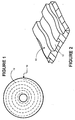
- Figures 1 and 2 show a phase-change DVD disc 10, hereinafter referred to as the disc 10.
- the disc 10 typically includes a rigid substrate that is coated with a recordable medium.
- the recordable medium may be made of a read/write material such as a phase change material.
- a spiral groove 12 is embedded in the disc 10.
- a laser beam can be used to heat and cool the recordable medium quickly to form marks having an amorphous state.
- the laser beam can also be used to erase the marks from the recordable medium by annealing the marks into a crystalline state. Data is represented by patterns of marks on the disc 10.
- the spiral groove 12 has a high frequency wobble.
- the high frequency wobble which gives the spiral groove 12 a slight sinusoidal wave, may be used to modulate the laser beam.
- a bit-accurate drive may generate a precise high frequency timing signal from such a modulated laser beam.
- Low frequency addressing information may also be imposed on the wobble (for example, by eliminating single wobble cycles in a pattern that conveys addressing information). The combination of the high frequency timing signal and the addressing information allows the bit-accurate drive to locate specific bits on the disc 10.
- Figure 1 merely provides an illustration to facilitate an understanding of the invention; it is not intended to show the disc 10 in detail or proper scale. For instance, pitch of the spiral, the thickness of the groove 12, the frequency of the wobble, etc., are not illustrated to scale.
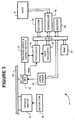
- Figure 3 shows the disc 10 and a bit-accurate DVD read/write drive 14 that follows a DVD format specification such as the DVD+RW format specification.
- the drive 14 includes a controller 16 for receiving a mode of operation from a host 8 (e.g., a personal computer).
- the modes of operation include a read mode and may include various write modes such as a write-append mode and an insert-edit mode.
- the drive 14 further includes a spindle motor 18 and motor control 20 for rotating the disc 10.
- the DVD drive 14 further includes an optical pickup unit 22, which typically includes a laser for generating a laser beam B1; and means (e.g., an optics assembly and photodetector array) for detecting a modulated beam B2.
- the optical pickup unit 22 generates an electrical signal RBK carrying data and timing/addressing information.
- the laser of the optical pickup unit 22 is driven by a laser driver 26. Power of the laser beam B1 depends upon the mode of operation of the drive 14. The laser power is controlled between various levels including a read level for reading data from the disc 10, an erase level for erasing data on the disc 10, and a write level for writing data to the disc 10.
- a processor 36 receives the electrical signal from the optical pickup unit 22.
- a tracking servo and wobble detection system 24 receives the electrical signal RBK from the processor 36.
- the tracking and wobble detection system 24 processes the electrical signal RBK to obtain addressing information and a precise high frequency timing signal.
- the addressing information and timing signal are supplied to the processor 36, which uses the addressing information and timing signal to control the timing of the laser driver 26 and to locate specific bits on the disc 10. Under command of the controller 16, the tracking servo and wobble detection system 24 also moves the optical pickup unit 22 along the disc 10.
- a bit-accurate drive derives timing accuracy from a high frequency reference signal.
- the bit-accurate drive also has the ability to unambiguously identify particular cycles in the reference signal.
- Generation of the high frequency signal using wobble of the spiral groove in the disc 10 is disclosed in Towner et al. US Serial No. 08/899,427,which was filed on July 24, 1997 and assigned to the assignee of the present invention.
- the reference signal cycles could be unambiguously identified by a systematic arrangement of missing wobble cycles, aligned with data sectors (e.g., in sync codewords).
- the ability to identify particular patterns of missing wobble cycles allows data sector addresses to be located.
- Data is written synchronously with the wobble.
- the combination of the high frequency reference signal and the address information derived from the missing wobbles allows data within data sectors to be identified. Moreover, the combination allows new data to be written to the disc without discontinuities in phase and frequency.
- a conventional data recovery circuit 28 also receives the electrical signal RBK from the processor 36 and recovers data from the electrical signal RBK.
- a decoder 30 demodulates the recovered data, arranges the demodulated data in error correction code (“ECC”) blocks in a RAM 32, and performs error correction on the ECC blocks. The error-corrected data is sent to the host 8.
- ECC error correction code
- the host 8 typically initiates an insert-edit operation by sending new data to the drive 14 in one or more two kilobyte (that is, "2K") sectors 50 (along with associated addressing information).
- Each 2K sector 50 includes a header 51, which contains address information.
- the 2K sectors 50 are buffered in the RAM 32 and arranged into 32K blocks.
- An encoder 34 performs ECC encoding on each 32K block of user data.
- Reed-Solomon Product Code (“RS-PC”) encoding is typically used in CD and DVD drives.
- Rows 52 and columns 54 of RS-PC codewords i.e., redundancy data
- the redundancy data may be interleaved with the user data.
- Resulting is an RS-PC block 56 that is typically 208 lines long and 182 bytes wide.
- the RS-PC blocks 56 are then modulation encoded by the encoder 34.
- a typical modulation code is a 2:10 Run Length Limited code.
- the eight bit bytes of the RS-PC blocks 56 are replaced with 16-bit symbol codewords.
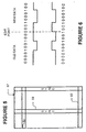
- Figure 5 shows a modulation-encoded block 57.
- the modulation-encoded block 57 includes sync codewords 59.
- the modulation-encoded header 58 of each modulation-encoded sector includes an address, address error detection and reserved symbol codewords.
- Each sync codeword 59 has a length of 32 bits.
- a sync codeword 59 is typically inserted after every 91 symbol codewords.
- Polarity refers to the high/low reflectivity characteristic of the disc 10. The polarity itself does not carry information, only the changes or transitions in polarity carry information. Thus, if the bit sequence "100" is old data, and the bit sequence "1001" is appended to the old data, either a "1001001” or a "1000001” will be read back, depending upon relative polarity of the old and new data (see Figure 6). If a new modulation-encoded block is appended to an old block, but the new block has an incompatible polarity at the edit point, a polarity conflict at the edit point will occur. As a result of the polarity conflict, an edge (i.e., transition) will be erroneously inserted into the modulation-encoded data. The unwanted edge will cause an error in the data.
- edge i.e., transition
- the drive 14 uses the combination of the addressing information and the timing signal to locate an edit bit on the disc 10.
- the edit bit is a specific bit at which the drive 14 begins or finishes a write operation.
- the controller 16 When the edit bit is located, the controller 16 has the modulation-encoded data sent to the laser driver 26, and commands the laser driver 26 to begin writing the data to the disc 10 (e.g., the controller 16 enables a write clock generator to send a write clock to the laser driver 26), starting at the edit bit. Timing of the laser driver 26 is controlled by the processor 36.
- the laser driver 26 causes the laser in an optical pickup unit 22 to write the data to the disc 10, starting at the edit bit.
- sync codeword One possible location for the edit bit is a sync codeword. Certain sync codewords are available in pairs, which differ by only one transition bit. This differing transition bit may be used as the edit bit. Exemplary sync codeword pairs for states 1 and 2 are as follows, with the double-underlined bit indicating the edit bit.
- Exemplary sync codeword pairs for states 3 and 4 are as follows, with the double-underlined bit indicating the differing transition bit.
- the drive 14 starts writing at the edit bit in the sync codeword, it does not matter which polarity is used at the edit point: the sync codeword will still be valid. Thus, by starting or stopping the write operation at the differing transition bit in the sync codeword, error caused by the polarity conflict will be avoided.
- the edit bit could be a bit in a codeword other than a sync codeword. Codewords pairs that differ by a bit may be designed for the reserved area of the header 58. This differing bit may be used as the edit bit. By making the edit at a bit in the reserved area of the header 58, the edit bit will follow the address information. In the event of an incorrect edit, the address information would not be affected.
- Figure 7 shows a general method of writing new data to a read/write disc.
- the host sends the one or more data sectors to the drive (block 102).
- the drive assembles the data sectors into 32K blocks, generates one or more RS-PC blocks (block 104), and modulation-encodes the RS-PC blocks (block 106).
- the drive locates an edit bit on the disc (block 108) and begins writing the modulation-encoded blocks to the disc, starting at the edit bit (block 100). In this manner, the new data is written to the disc.
- bit-accurate drive that can edit data on an optical read/write medium without the use of edit gaps.
- Starting or stopping a write operation at an appropriately selected bit avoids introducing any additional data due to polarity incompatibilities between old and new data.
- Starting or stopping the write operation at a differing transition bit in a sync codeword avoids any errors that might arise from polarity conflicts.
- the invention is not limited to the specific embodiment described and illustrated above.
- the editing could end at an edit bit instead of starting at the edit bit.
- an edit-insert operation could be performed in which the drive start writing data at the beginning of the disc 10 and ending at an edit bit on the disk. Therefore, the invention is construed according to the claims that follow.
Landscapes
- Engineering & Computer Science (AREA)
- Signal Processing (AREA)
- Multimedia (AREA)
- Optical Recording Or Reproduction (AREA)
- Signal Processing For Digital Recording And Reproducing (AREA)
- Information Retrieval, Db Structures And Fs Structures Therefor (AREA)
Applications Claiming Priority (2)
| Application Number | Priority Date | Filing Date | Title |
|---|---|---|---|
| US09/231,045 US6501721B2 (en) | 1999-01-14 | 1999-01-14 | Spliceless editing of a read/write optical medium |
| US231045 | 1999-01-14 |
Publications (2)
| Publication Number | Publication Date |
|---|---|
| EP1020859A1 EP1020859A1 (en) | 2000-07-19 |
| EP1020859B1 true EP1020859B1 (en) | 2006-07-19 |
Family
ID=22867557
Family Applications (1)
| Application Number | Title | Priority Date | Filing Date |
|---|---|---|---|
| EP00300074A Expired - Lifetime EP1020859B1 (en) | 1999-01-14 | 2000-01-07 | Optical storage medium |
Country Status (5)
| Country | Link |
|---|---|
| US (1) | US6501721B2 (enExample) |
| EP (1) | EP1020859B1 (enExample) |
| JP (1) | JP3981228B2 (enExample) |
| CN (1) | CN1192387C (enExample) |
| DE (1) | DE60029365T2 (enExample) |
Families Citing this family (13)
| Publication number | Priority date | Publication date | Assignee | Title |
|---|---|---|---|---|
| KR100329391B1 (ko) * | 1999-01-04 | 2002-03-22 | 구자홍 | 디지털 데이터 스트림의 기록방법 및 장치 |
| JP3679643B2 (ja) * | 1999-02-26 | 2005-08-03 | 三洋電機株式会社 | ディスク記録装置 |
| JP3505452B2 (ja) * | 1999-11-05 | 2004-03-08 | 三洋電機株式会社 | ディスク記録装置 |
| US6741547B2 (en) * | 2000-08-10 | 2004-05-25 | Ricoh Company, Ltd. | Optical recording medium having short wobble period length |
| FI112121B (fi) * | 2000-12-11 | 2003-10-31 | Rafsec Oy | Älytarraraina, menetelmä sen valmistamiseksi, menetelmä kantorainan valmistamiseksi ja älytarrarainan älytarran rakenneosa |
| KR100829013B1 (ko) * | 2001-11-06 | 2008-05-15 | 엘지전자 주식회사 | 진폭 편이 변조 방식을 이용한 광디스크의 워블 어드레싱방법 |
| KR100844847B1 (ko) * | 2001-12-06 | 2008-07-08 | 엘지전자 주식회사 | 광디스크의 워블신호 기록방법 및 그에 따른 광디스크 |
| EP1372151B1 (en) * | 2002-05-13 | 2005-07-13 | International Business Machines Corporation | Data overwriting in probe-based data storage devices |
| KR20070020043A (ko) * | 2004-04-23 | 2007-02-16 | 코닌클리케 필립스 일렉트로닉스 엔.브이. | 실시간 정보의 심리스 기록 |
| US20060072425A1 (en) * | 2004-09-30 | 2006-04-06 | Hanks Darwin M | Array-based optical head |
| US7468815B2 (en) * | 2004-09-30 | 2008-12-23 | Hewlett-Packard Development Company, L.P. | Optical data processing using photo-detector array and framing marks on optical media |
| US20080080326A1 (en) * | 2006-09-29 | 2008-04-03 | Media Tek Inc. | Optical recording method and apparatus |
| US20100302919A1 (en) * | 2005-10-27 | 2010-12-02 | Mediatek Inc. | Optical Recording Method and Apparatus |
Citations (1)
| Publication number | Priority date | Publication date | Assignee | Title |
|---|---|---|---|---|
| WO2000034952A1 (en) * | 1998-12-09 | 2000-06-15 | Koninklijke Philips Electronics N.V. | Method and device for recording information in units |
Family Cites Families (6)
| Publication number | Priority date | Publication date | Assignee | Title |
|---|---|---|---|---|
| US5343455A (en) | 1990-04-05 | 1994-08-30 | Hitachi, Ltd. | Digital signal overlapped or joined recording method and apparatus |
| US5995470A (en) * | 1996-04-11 | 1999-11-30 | Sony Corporation | Method of recording and reproducing information signals and apparatus for editing the same |
| JP3589802B2 (ja) | 1996-08-22 | 2004-11-17 | パイオニア株式会社 | 情報記録方法及び装置 |
| JP2862850B2 (ja) | 1997-04-18 | 1999-03-03 | 株式会社東芝 | 情報記録方法と情報記録装置 |
| JPH10334616A (ja) | 1997-05-30 | 1998-12-18 | Sony Corp | 光ディスク装置およびデータ記録方法 |
| US6046969A (en) * | 1998-03-17 | 2000-04-04 | Hewlett-Packard Company | Multiple clock tracks for erasable and rewriteable optical disks |
-
1999
- 1999-01-14 US US09/231,045 patent/US6501721B2/en not_active Expired - Lifetime
- 1999-08-13 CN CNB991179048A patent/CN1192387C/zh not_active Expired - Fee Related
-
2000
- 2000-01-07 EP EP00300074A patent/EP1020859B1/en not_active Expired - Lifetime
- 2000-01-07 DE DE60029365T patent/DE60029365T2/de not_active Expired - Lifetime
- 2000-01-12 JP JP2000003684A patent/JP3981228B2/ja not_active Expired - Fee Related
Patent Citations (1)
| Publication number | Priority date | Publication date | Assignee | Title |
|---|---|---|---|---|
| WO2000034952A1 (en) * | 1998-12-09 | 2000-06-15 | Koninklijke Philips Electronics N.V. | Method and device for recording information in units |
Also Published As
| Publication number | Publication date |
|---|---|
| US20020126595A1 (en) | 2002-09-12 |
| JP3981228B2 (ja) | 2007-09-26 |
| US6501721B2 (en) | 2002-12-31 |
| DE60029365T2 (de) | 2007-02-15 |
| EP1020859A1 (en) | 2000-07-19 |
| CN1260569A (zh) | 2000-07-19 |
| DE60029365D1 (de) | 2006-08-31 |
| CN1192387C (zh) | 2005-03-09 |
| JP2000215608A (ja) | 2000-08-04 |
Similar Documents
| Publication | Publication Date | Title |
|---|---|---|
| JP4733834B2 (ja) | ユニットで情報を記録する方法及び装置 | |
| KR100434210B1 (ko) | 디지털데이터기록/재생장치및방법과,디스크형기록매체 | |
| EP1020859B1 (en) | Optical storage medium | |
| KR100470377B1 (ko) | 데이터 기록 장치 및 데이터 기록 제어기 | |
| CN1213427C (zh) | 以单元记录信息的方法和设备 | |
| EP1102261A2 (en) | Data recorder capable to prevent buffer underrun errors | |
| EP0938092B1 (en) | Information recording apparatus and method | |
| EP0272135B1 (en) | Optical disk and optical disk apparatus | |
| EP0944088A2 (en) | Optical disk | |
| EP1102262A2 (en) | Controller for data recorder to prevent buffer underrun errors | |
| EP0991061B1 (en) | Optical recording method and apparatus for recording a link part | |
| US6956799B1 (en) | Phase discontinuity compensation in a bit-accurate optical drive | |
| KR100464409B1 (ko) | 광기록매체상의 상대 어드레스 검출 및 보정 장치 및 방법 | |
| WO2002031818A2 (en) | Method and device for recording information in units | |
| JP2000040306A (ja) | 書換可能な記録膜を用いた追記型光ディスク、および光ディスク初期化方法および光ディスク再生方法および光ディスク追記方法、および光ディスク初期化装置および光ディスク再生装置および光ディスク追記装置 | |
| JP2746873B2 (ja) | 情報処理装置 | |
| JP3708617B2 (ja) | Eccメモリ制御システム | |
| JP2686802B2 (ja) | 光ディスクに対する記録方法 | |
| US7167427B1 (en) | Data recorder | |
| JPH08180611A (ja) | データ記録再生方法及びその装置、並びにデータ伝送方法及びその装置 | |
| JPH08195033A (ja) | データ記録方法、データ再生方法、データ記録再生方法及びディスク状記録媒体 | |
| JPH10308080A (ja) | 情報記録媒体 |
Legal Events
| Date | Code | Title | Description |
|---|---|---|---|
| PUAI | Public reference made under article 153(3) epc to a published international application that has entered the european phase |
Free format text: ORIGINAL CODE: 0009012 |
|
| AK | Designated contracting states |
Kind code of ref document: A1 Designated state(s): DE FR GB |
|
| AX | Request for extension of the european patent |
Free format text: AL;LT;LV;MK;RO;SI |
|
| 17P | Request for examination filed |
Effective date: 20000911 |
|
| AKX | Designation fees paid |
Free format text: DE FR GB |
|
| RAP1 | Party data changed (applicant data changed or rights of an application transferred) |
Owner name: HEWLETT-PACKARD COMPANY, A DELAWARE CORPORATION |
|
| 17Q | First examination report despatched |
Effective date: 20031017 |
|
| GRAP | Despatch of communication of intention to grant a patent |
Free format text: ORIGINAL CODE: EPIDOSNIGR1 |
|
| GRAS | Grant fee paid |
Free format text: ORIGINAL CODE: EPIDOSNIGR3 |
|
| GRAA | (expected) grant |
Free format text: ORIGINAL CODE: 0009210 |
|
| AK | Designated contracting states |
Kind code of ref document: B1 Designated state(s): DE FR GB |
|
| REG | Reference to a national code |
Ref country code: GB Ref legal event code: FG4D |
|
| REF | Corresponds to: |
Ref document number: 60029365 Country of ref document: DE Date of ref document: 20060831 Kind code of ref document: P |
|
| EN | Fr: translation not filed | ||
| PLBE | No opposition filed within time limit |
Free format text: ORIGINAL CODE: 0009261 |
|
| STAA | Information on the status of an ep patent application or granted ep patent |
Free format text: STATUS: NO OPPOSITION FILED WITHIN TIME LIMIT |
|
| 26N | No opposition filed |
Effective date: 20070420 |
|
| PG25 | Lapsed in a contracting state [announced via postgrant information from national office to epo] |
Ref country code: FR Free format text: LAPSE BECAUSE OF FAILURE TO SUBMIT A TRANSLATION OF THE DESCRIPTION OR TO PAY THE FEE WITHIN THE PRESCRIBED TIME-LIMIT Effective date: 20070511 |
|
| PG25 | Lapsed in a contracting state [announced via postgrant information from national office to epo] |
Ref country code: FR Free format text: LAPSE BECAUSE OF FAILURE TO SUBMIT A TRANSLATION OF THE DESCRIPTION OR TO PAY THE FEE WITHIN THE PRESCRIBED TIME-LIMIT Effective date: 20060719 |
|
| REG | Reference to a national code |
Ref country code: GB Ref legal event code: 732E Free format text: REGISTERED BETWEEN 20120329 AND 20120404 |
|
| PGFP | Annual fee paid to national office [announced via postgrant information from national office to epo] |
Ref country code: GB Payment date: 20171222 Year of fee payment: 19 |
|
| PGFP | Annual fee paid to national office [announced via postgrant information from national office to epo] |
Ref country code: DE Payment date: 20170816 Year of fee payment: 19 |
|
| REG | Reference to a national code |
Ref country code: DE Ref legal event code: R119 Ref document number: 60029365 Country of ref document: DE |
|
| GBPC | Gb: european patent ceased through non-payment of renewal fee |
Effective date: 20190107 |
|
| PG25 | Lapsed in a contracting state [announced via postgrant information from national office to epo] |
Ref country code: DE Free format text: LAPSE BECAUSE OF NON-PAYMENT OF DUE FEES Effective date: 20190801 |
|
| PG25 | Lapsed in a contracting state [announced via postgrant information from national office to epo] |
Ref country code: GB Free format text: LAPSE BECAUSE OF NON-PAYMENT OF DUE FEES Effective date: 20190107 |