EP1020548B1 - Card clothing for flats of a carding machine - Google Patents
Card clothing for flats of a carding machine Download PDFInfo
- Publication number
- EP1020548B1 EP1020548B1 EP00100677A EP00100677A EP1020548B1 EP 1020548 B1 EP1020548 B1 EP 1020548B1 EP 00100677 A EP00100677 A EP 00100677A EP 00100677 A EP00100677 A EP 00100677A EP 1020548 B1 EP1020548 B1 EP 1020548B1
- Authority
- EP
- European Patent Office
- Prior art keywords
- card
- wire
- area
- support element
- wires
- Prior art date
- Legal status (The legal status is an assumption and is not a legal conclusion. Google has not performed a legal analysis and makes no representation as to the accuracy of the status listed.)
- Expired - Lifetime
Links
Images

Classifications
-
- D—TEXTILES; PAPER
- D01—NATURAL OR MAN-MADE THREADS OR FIBRES; SPINNING
- D01G—PRELIMINARY TREATMENT OF FIBRES, e.g. FOR SPINNING
- D01G15/00—Carding machines or accessories; Card clothing; Burr-crushing or removing arrangements associated with carding or other preliminary-treatment machines
- D01G15/84—Card clothing; Manufacture thereof not otherwise provided for
- D01G15/88—Card clothing; Manufacture thereof not otherwise provided for formed from metal sheets or strips
-
- D—TEXTILES; PAPER
- D01—NATURAL OR MAN-MADE THREADS OR FIBRES; SPINNING
- D01G—PRELIMINARY TREATMENT OF FIBRES, e.g. FOR SPINNING
- D01G15/00—Carding machines or accessories; Card clothing; Burr-crushing or removing arrangements associated with carding or other preliminary-treatment machines
- D01G15/84—Card clothing; Manufacture thereof not otherwise provided for
-
- D—TEXTILES; PAPER
- D01—NATURAL OR MAN-MADE THREADS OR FIBRES; SPINNING
- D01G—PRELIMINARY TREATMENT OF FIBRES, e.g. FOR SPINNING
- D01G15/00—Carding machines or accessories; Card clothing; Burr-crushing or removing arrangements associated with carding or other preliminary-treatment machines
- D01G15/02—Carding machines
- D01G15/12—Details
- D01G15/14—Constructional features of carding elements, e.g. for facilitating attachment of card clothing
- D01G15/24—Flats or like members
-
- D—TEXTILES; PAPER
- D01—NATURAL OR MAN-MADE THREADS OR FIBRES; SPINNING
- D01G—PRELIMINARY TREATMENT OF FIBRES, e.g. FOR SPINNING
- D01G15/00—Carding machines or accessories; Card clothing; Burr-crushing or removing arrangements associated with carding or other preliminary-treatment machines
- D01G15/84—Card clothing; Manufacture thereof not otherwise provided for
- D01G15/90—Lags, e.g. for jute cards
Definitions
- the invention relates to a scratch covering for a cover Card according to the preamble of claim 1 with a carrier element and a number of each with at least one receiving section received in the carrier element Scratching wires, each of which is at least one outside of the carrier element exposed processing section has as well as one for producing such a scratching covering usable support element.
- a card is used in the production of yarn for parallelization of the individual fibers one of disordered fibers existing raw material used.
- a card is usually used for this essentially from one essentially in shape of a circular cylinder and a number of along an approximately parallel to the surface of the drum, predetermined path with respect to the drum movable Lids.
- the Tambour on its outer surface for example in the form of Sawtooth wires formed drum set while the Cover on its along the given path facing the drum Side are equipped with cover sets.
- This too Lid sets can be in the form of parallel to the given Saw tooth wire sections extending in the path his.
- lid sets in the form of Scratch coverings of the type described above for use.
- the invention is based on the object an inexpensive and low-wear scratching covering at the beginning Provide described type with which reliable operation a card can be guaranteed with little effort can.
- the short fibers collecting the lid proven if the length of the outside of the support member exposed machining sections less than 3 mm, preferably less than 2 mm, particularly preferably less than Is 1.5 mm.
- scratch wires For holding the scratch wires in the carrier element can the scratch wires on their facing away from the processing section End of the receiving section with one on the back of the support element adjacent holding section his.
- the scraper wires two outside of Carrier element exposed processing sections and two have receiving sections penetrating the carrier element, the receiving sections via a on the back of the Carrier element adjacent connecting section with each other are connected.
- Such scratch wires can for example in be formed substantially U-shaped, each of the two outer Leg of such a U-shaped scraper wire one processing section exposed outside the carrier element and a receiving portion received in the support member has and the two outer legs together connecting legs of the scratch wire on the back of the support element rests.
- Such machining tips are conventionally thereby made that scratch wire with a constant length Cross-sectional area in a perpendicular to its longitudinal axis extending cutting plane at one of its ends to provide of the tip surface segment running obliquely to the longitudinal axis be ground, embossed or punched.
- the scratch wires of a scratch covering according to the invention in the Fiber material has proven to be particularly favorable if one of the tip surface segments approximately parallel to the longitudinal axis of the scraper wire and preferably an acute angle from about 5 to 30 °, preferably about 5 to 20 °, particularly preferably about 12 ° with one touching the machining tip Includes surface normals on the front of the support element.
- the distance is between the front of the receiving area and the front of the fastening area in a perpendicular to the front of the recording area extending direction for attaching the retaining clip available without going through the front of the fastening area of the holding part of the holding clip the processing of the textile fibers with those from the front of the Recording area of the support element protruding processing sections the scratch wire is affected.
- the support member. formed in the manner of a carrier tape is the processing sections of the scraper wires facing back in a roughly parallel to the front the plane of the machining area is arranged, the front of the mounting area also in one approximately parallel to the front of the machining area extending plane can be arranged.
- the scratch coverings according to the invention themselves extending over the entire width of the reel of a card Width, while its length is parallel to the given one Machining route direction is essential is shorter than the width of the drum. Accordingly, it is in progress the processing section facing the drum the processing area of the carrier element usually in essentially rectangular. This can be a reliable attachment the scratch coating on the flat bar are ensured, if the rectangular front on at least one, preferably about two of their longer side edges parallel to the fastening area.
- the inventive Scraps over one with a holding part on the Front of the fastening area of the support element and starting from there towards the back of the support element and, if necessary, extending holding element to be attached to the flat bar of a card, wherein a particularly reliable fastening is ensured, if the holding element in the fastening area of the carrier element has penetrating fastening part.
- a carrier element suitable for such scratch coverings essentially characterized in that there is one for receiving the receiving sections of the scraper wires serving area with a has a substantially flat front, which at least one of its edges merges into a fastening area, the Front with respect to the front of the recording area is offset towards the back of the carrier element.
- a carrier element is preferably made of an elastic Plastic, such as polyvinyl chloride, polyurethane or Polyamide, possibly with appropriate plasticizers.
- carrier elements made of plastic, in particular made of PVC. It can at least increase the strength one, preferably two spaced apart in the thickness direction Tissue inserts can be embedded in the carrier element.
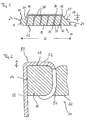
- the scratch coating shown in the drawing is essentially of a carrier element 10 and a number of used in this support member 10.
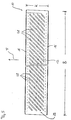
- Scratching wires 30 a synopsis of FIGS. 1 and 5 shows that the carrier element 10 in the manner of a carrier tape with a width B, which corresponds essentially to the width of the cardboard reel, and a much shorter length K in a parallel to the direction of movement indicated by the arrow F in FIG. 5 the lid runs along the specified path Direction is formed. From Fig. 1 it appears that the Carrier element a central receiving area 12 with a comparatively has a large thickness into which the scratch wires 30 are inserted, the opposite of each other on its two Edges each in a fastening area 16 less Fat passes.
- the back 22 of the carrier element essentially formed flat, while the essentially flat and parallel to the rear 22 front 14 of the receiving area receiving the scratch wires 30 12 greater thickness on their two opposite one another Edges over towards the back 22 extending steps 20 in the also substantially flat and approximately parallel to the rear side 22 of the carrier element 10 extending front sides 18 of the fastening area 16. Accordingly, the front faces 18 are the fastening areas 16 with respect to the front 14 of the receiving area 12 in the direction offset in parallel on the rear side 22 of the carrier element 10.
- the edge regions 16 of reduced thickness of the carrier element 10 are available for attaching to attach the scratching surface on a flat bar usually used holding clips Available.
- the difference in height d between the Front 14 of the receiving area 12 and the front 18 the attachment areas 16 an attachment of the retaining clips enables the effectiveness of the over the front 14 of the receiving area projecting and exposed processing sections 36 of the scratch wires 30 leaves uninfluenced.
- FIG. 2 The attachment of retaining clips 50 to the opposite one another Fastening areas 16 of the carrier element 10 is exemplary in .Fig. 2 shown.
- the end of the fastening part facing away from the holding part 52 54 bears against the rear side 22 of the carrier element and thus makes a reliable fastening of the holding clip 50 the carrier element safely.
- the fat d 'of the holding part 52 in a direction perpendicular to the front 18 of the fastening region 16 extending direction is less than the height difference d between the front 14 of the Receiving area 12 and the front 18 of the mounting area 16. This ensures that the effectiveness of the outside of the carrier element 10 exposed processing segments 36 of the scratch wires 30 by attaching the retaining clip 50 is not affected.
- the individual inserted into the receiving area 12 of the support member 10 Scratching wires 30 are formed in a substantially U-shape and have two outer legs 32, one over the back 22 of the support element adjoining connecting section 48 are interconnected.
- Each of the outer legs 32 has one received in the receiving area 12 of the carrier element 10 Receiving section 34 and one over the front 14 of the receiving area 12 projecting, exposed Processing section 36 on.
- the length L of the receiving sections 34 in the direction of the longitudinal axis 31 of the scraper wire 30 much larger than the length 1 of the processing sections 36, the length 1 being approximately 1 mm and the length L approximately 6 mm is.
- the Width b of the individual scratch wires in a direction perpendicular to the direction of movement F and parallel to the front 14 of the recording area 12 running direction is the one in the drawing shown scratching surface about 0.2 mm, while the thickness D of the scratch wire in a perpendicular to that through the longitudinal axis 31 and the width direction spanned plane Direction is approximately 0.48 mm (see FIG. 4). Thereby is guaranteed with sufficient stability of the Scraper wire in a direction parallel to the direction of movement F.
- This machining tip 38 will by two enclosing an acute angle ⁇ of about 16 ° Tip surface segments 40 and 46 formed.
- This in Direction of the lid movement indicated by arrow F. along the specified machining path during a machining process front tip surface segment 46 runs approximately parallel to the longitudinal axis 31 of the scraper wire 30 and closes an acute angle ⁇ of about 12 ° with the machining tip 38 touching surface normals on the front 14 of the recording area w. That the front tip surface segment 46 opposite rear tip surface segment 40 closes with the longitudinal axis 31 of the scraper wheel 30 the acute angle.
- the invention is not explained on the basis of the drawing Embodiment limited. Rather, it is about it thought the angle between the front tip surface segment 46 and the surface normal touching the machining tip 38 on the front 14 of the receiving area 12 in one area to vary between 5 ° and 20 °.
- the angle between the front tip surface segment 46 and the surface normal touching the machining tip 38 on the front 14 of the receiving area 12 in one area to vary between 5 ° and 20 °.
- a square, round or oval cross section become.
- an embodiment is also contemplated in which the front sides 18 of the fastening areas 16 are starting from the side surfaces 24 towards the rear 22 of the support member 10, and so an even more reliable To enable attachment of the retaining clips 50.
Abstract
Description
Die Erfindung betrifft einen Kratzenbelag für Deckel einer Karde nach dem Oberbegriff des Anspruchs 1 mit einem Trägerelement und einer Anzahl von jeweils mit mindestens einem Aufnahmeabschnitt in dem Trägerelement aufgenommenen Kratzendrähten, von denen jeder mindestens einen außerhalb des Trägerelementes freiliegenden Bearbeitungsabschnitt aufweist sowie ein zum Herstellen eines derartigen Kratzenbelags einsetzbares Trägerelement.The invention relates to a scratch covering for a cover Card according to the preamble of claim 1 with a carrier element and a number of each with at least one receiving section received in the carrier element Scratching wires, each of which is at least one outside of the carrier element exposed processing section has as well as one for producing such a scratching covering usable support element.
Eine Karde wird bei der Herstellung von Garn zum Parallelisieren der einzelnen Fasern eines aus ungeordneten Fasern bestehenden Rohmaterials eingesetzt. Dazu besteht eine Karde üblicherweise im wesentlichen aus einem im wesentlichen in Form eines Kreiszylinders gebildeten Tambour und einer Anzahl von längs einer sich etwa parallel zur Mantelfläche des Tambours erstreckenden, vorgegebenen Bahn bezüglich dem Tambour bewegbaren Deckeln. Zum Bearbeiten der Fasern des Rohmaterials weist der Tambour auf seiner Mantelfläche eine beispielsweise in Form von Sägezahndrähten gebildete Tambourgarnitur auf, während die Deckel an ihrer längs der vorgegebenen Bahn dem Tambour zugewandten Seite mit Deckelgarnituren bestückt sind. Auch diese Deckelgarnituren können in Form von sich parallel zu der vorgegebenen Bahn erstreckenden Sägezahndrahtabschnitten gebildet sein. Daneben kommen jedoch auch Deckelgarnituren in Form von Kratzenbelägen der vorstehend beschriebenen Art zum Einsatz. Diese zeichnen sich im Vergleich zu aus Sägezahndrahtabschnitten gebildeten Ganzstahlgarnituren durch ein wesentlich geringeres Gewicht und durch deutlich geringere Herstellungskosten aus. Dabei kann das Gewicht eines mit einem Kratzenbelag der vorstehend beschriebenen Art ausgestatteten Deckels weniger als die Hälfte des Gewichtes eines Deckels mit einer aus Sägezahndrähten gebildeten Deckelgarnitur betragen. Das führt nicht nur zu einem deutlich geringeren Energieverbrauch beim Betrieb einer Karde, sondern auch zu einem geringeren Verschleiß, weil die Bewegung und Führung der mit einem Kratzenbelag der vorstehend beschriebenen Art ausgestatteten Deckel längs der vorgegebenen Strecke mit einem besonders geringen Kraftaufwand erfolgen kann. Aus diesem Grund werden insbesondere bei der Herstellung von preiswerten Garnen mit geringen Qualitätsanforderungen zunehmend Kratzenbeläge der vorstehend beschriebenen Art eingesetzt.A card is used in the production of yarn for parallelization of the individual fibers one of disordered fibers existing raw material used. A card is usually used for this essentially from one essentially in shape of a circular cylinder and a number of along an approximately parallel to the surface of the drum, predetermined path with respect to the drum movable Lids. For processing the fibers of the raw material, the Tambour on its outer surface, for example in the form of Sawtooth wires formed drum set while the Cover on its along the given path facing the drum Side are equipped with cover sets. This too Lid sets can be in the form of parallel to the given Saw tooth wire sections extending in the path his. In addition, there are also lid sets in the form of Scratch coverings of the type described above for use. These are distinguished from sawtooth wire sections formed all-steel sets by a much lower Weight and by significantly lower manufacturing costs. there can be the weight of one with a scratch covering of the above described type equipped lid less than half the weight of a lid with one formed from sawtooth wires Cover set. That doesn't just lead to one significantly lower energy consumption when operating a card, but also less wear and tear because of the movement and guiding the with a scratch coating of those described above Kind equipped lid along the given route can be done with particularly little effort. Out for this reason, especially in the manufacture of inexpensive Yarns with low quality requirements increasingly Scratch coverings of the type described above used.
Dabei hat es sich jedoch als problematisch erwiesen, daß die im allgemeinen aus einem elastischen Kunststoff und/oder einer Mehrzahl von zusammenvulkanisierten Gewebeschichten bestehenden bandförmigen Trägerelemente im Bereich der Aufnahmeabschnitte der Kratzendrähte schon nach kurzer Zeit ausreißen, weil während der Verarbeitung des Fasermaterials im Bereich der Aufnahmeabschnitte der Kratzendrähte erhebliche Kräfte auf das Trägerelement ausgeübt werden. Zur Beseitigung dieses Mangels wurde in der CH 636 134 bereits vorgeschlagen, die Trägerelemente von Kratzenbelägen der eingangs beschriebenen Art mit bandförmigen Verstärkungseinlagen zu versehen. Die Herstellung derartiger Trägerelemente ist jedoch mit vergleichsweise hohen Kosten verbunden, wodurch die durch den Einsatz dieser Kratzenbeläge zu erzielenden Kostenvorteile zumindest teilweise wieder zunichte gemacht werden.However, it has proven problematic that which are generally made of an elastic plastic and / or a A plurality of fabric layers vulcanized together band-shaped carrier elements in the area of the receiving sections the scratch wires tear out after a short time, because during the processing of the fiber material in the area of Receiving sections of the scratch wires have significant forces on it Carrier element are exercised. To remedy this shortcoming The support elements have already been proposed in CH 636 134 of scratch coverings of the type described above to provide band-shaped reinforcement inserts. The production such carrier elements is, however, comparatively high Cost associated with this through the use of these scratch coverings cost advantages to be achieved at least partially again be nullified.
Weiter hat es sich beim Einsatz von Kratzenbelägen der eingangs beschriebenen Art als nachteilhaft erwiesen, daß sich eine große Menge von Kurzfasern im Bereich der Bearbeitungsabschnitte der Kratzendrähte ansammelt, was zur Gewährleistung eines zuverlässigen Betriebs der Karde eine häufige Reinigung der Kratzenbeläge der Deckel erforderlich macht.Furthermore, it has the use of scratch coverings type described above proved to be disadvantageous that a large amount of short fibers in the processing section of the scratch wires accumulates, which ensures a reliable operation of the card a frequent cleaning of the Scratch coverings that make the cover necessary.
Ferner sind Kratzenbeläge nach dem Oberbegriff des Anspruchs 1 in der GB-A-1 474 889 beschrieben.Furthermore, scratch coverings according to the preamble of claim 1 are described in GB-A-1 474 889.
Angesichts der vorstehend beschriebenen Probleme im Stand der Technik liegt der Erfindung die Aufgabe zugrunde, einen preiswerten und verschleißarmen Kratzenbelag der eingangs beschriebenen Art bereitzustellen, mit dem ein zuverlässiger Betrieb einer Karde mit geringem Aufwand gewährleistet werden kann.Given the problems described in the State of the art, the invention is based on the object an inexpensive and low-wear scratching covering at the beginning Provide described type with which reliable operation a card can be guaranteed with little effort can.
Erfindungsgemäß wird diese Aufgabe durch die im Kennzeichnenden Teil des Anspruchs 1 angegebene Weiterbildung der bekannten Kratzenbeläge der eingangs beschriebenen Art gelöst. Bevorzugte Ausführungsformen der Erfindung sind in den abhängigen Patentansprüchen angegeben. According to the invention, this object is achieved by the further development specified in the characterizing part of claim 1 the known scratch coverings of the one described above Kind of solved. preferred Embodiments of the invention are in the dependent claims specified.
Im Hinblick auf die Verschleißfestigkeit erfindungsgemäßer Kratzenbeläge hat es sich als besonders vorteilhaft erwiesen, wenn das Verhältnis der Länge des in dem Trägerelement aufgenommenen Aufnahmeabschnittes der Kratzendrähte zu derjenigen des außerhalb des Trägerelementes freiliegenden Bearbeitungsabschnittes mindestens 3 : 1, vorzugsweise mindestens 5 : 1 beträgt. In terms of wear resistance according to the invention It has proven to be particularly advantageous if the ratio of the length of the in the support member recorded receiving portion of the scratch wires to that of the processing section exposed outside the carrier element at least 3: 1, preferably at least 5: 1 is.
Im Hinblick auf die Reduzierung der Menge der sich während des Betriebs einer Karde im Bereich der Kratzenbeläge der Deckel ansammelnden Kurzfasern hat es sich als besonders vorteilhaft erwiesen, wenn die Länge der außerhalb des Trägerelementes freiliegenden Bearbeitungsabschnitte weniger als 3 mm, vorzugsweise weniger als 2 mm, besonders bevorzugt weniger als 1,5 mm beträgt.With regard to reducing the amount of yourself during the operation of a card in the area of the scratch coverings of the It has proven to be particularly advantageous for the short fibers collecting the lid proven if the length of the outside of the support member exposed machining sections less than 3 mm, preferably less than 2 mm, particularly preferably less than Is 1.5 mm.
Produktionstechnisch hat es sich als besonders vorteilhaft erwiesen, wenn der Aufnahmeabschnitt der Kratzendrähte das Trägerelement ausgehend von dessen dem Bearbeitungsabschnitt abgewandten Rückseite bis zu dessen dem Bearbeitungsabschnitt zugewandten Vorderseite durchdringt, weil die Kratzendrähte dann bei der Herstellung erfindungsgemäße Kratzenbeläge ohne Beschädigung der während der Bearbeitung des Fasermaterials im allgemeinen dem Tambour zugewandten Vorderseite des Trägerelementes so weit in dessen Rückseite eingeführt werden können, bis der Bearbeitungsabschnitt aus der Vorderseite des Trägerelementes heraustritt.In terms of production technology, it has proven to be particularly advantageous proven when the receiving portion of the scratch wires the carrier element based on the processing section back facing away from the processing section penetrates facing front because the scratch wires then in the manufacture of scratch coverings according to the invention without damage who during the processing of the fiber material in general front of the support element facing the drum can be inserted so far into the back, until the processing section from the front of the carrier element emerges.
Zum Festhalten der Kratzendrähte in dem Trägerelement können die Kratzendrähte an ihrem dem Bearbeitungsabschnitt abgewandten Ende des Aufnahmeabschnittes mit einem an der Rückseite des Trägerelementes anliegenden Halteabschnitt ausgestattet sein. In diesem Zusammenhang hat es sich als besonders zweckmäßig erwiesen, wenn die Kratzendrähte zwei außerhalb des Trägerelementes freiliegende Bearbeitungsabschnitte sowie zwei das Trägerelement durchdringende Aufnahmeabschnitte aufweisen, wobei die Aufnahmeabschnitte über einen an der Rückseite des Trägerelementes anliegenden Verbindungsabschnitt miteinander verbunden sind. Derartige Kratzendrähte können beispielsweise im wesentlichen U-förmig gebildet sein, wobei jeder der beiden äußeren Schenkel eines derartigen U-förmigen Kratzendrahtes einen außerhalb des Trägerelementes freiliegenden Bearbeitungsabschnitt und einen in dem Trägerelement aufgenommenen Aufnahmeabschnitt aufweist und der die beiden äußeren Schenkel miteinander verbindende Schenkel des Kratzendrahtes an der Rückseite des Trägerelementes anliegt. For holding the scratch wires in the carrier element can the scratch wires on their facing away from the processing section End of the receiving section with one on the back of the support element adjacent holding section his. In this context, it has turned out to be special Proven useful if the scraper wires two outside of Carrier element exposed processing sections and two have receiving sections penetrating the carrier element, the receiving sections via a on the back of the Carrier element adjacent connecting section with each other are connected. Such scratch wires can for example in be formed substantially U-shaped, each of the two outer Leg of such a U-shaped scraper wire one processing section exposed outside the carrier element and a receiving portion received in the support member has and the two outer legs together connecting legs of the scratch wire on the back of the support element rests.
Im Hinblick auf eine weitere Verbesserung der Verschleißfestigkeit erfindungsgemäßer Kratzenbeläge hat es sich als vorteilhaft erwiesen, wenn der Kratzendraht in einer senkrecht zu seiner Längsachse und etwa senkrecht zu der Richtung der während der Verarbeitung des Rohmaterials auf ihn' einwirkenden Bearbeitungskräfte verlaufenden Richtung eine Breite von mindestens 0,2 mm, vorzugsweise mindestens 0,4 mm aufweist, weil auf diese Weise der während der Verarbeitung des Rohmaterials über die Kratzendrähte auf das Trägerelement ausgeübte Druck ohne Beeinträchtigung der Funktion der Karde geringgehalten werden kann, um so dem Ausreissen des Trägerelementes im Bereich der Aufnahmeabschnitte der Kratzendrähte weiter entgegenzuwirken.With a view to further improving wear resistance it has it according to the invention proven to be advantageous if the scratch wire in a vertical to its longitudinal axis and approximately perpendicular to the direction those acting on it during the processing of the raw material Machining forces direction a width of at least 0.2 mm, preferably at least 0.4 mm, because in this way the while processing the raw material exerted on the carrier element via the scratch wires Low pressure without affecting the function of the card can be so as to tear out the support member to counteract further in the area of the receiving sections of the scraper wires.
Im Hinblick auf die Sicherstellung einer möglichst hohen Stabilität des Trägerelementes muß dafür gesorgt werden, daß während des Einführens der Kratzendrähte in das Trägerelement keine zu große Materialverdrängung innerhalb des Trägerelementes erfolgt. Daher ist es im Hinblick auf die Sicherstellung einer hohen Stabilität des Trägerelementes bevorzugt, wenn die Kratzendrähte eine möglichst geringe Querschnittsfläche in einer senkrecht zu ihrer Längsrichtung verlaufenden Schnittebene aufweisen. Andererseits muß im Hinblick auf die während der.Bearbeitung des Fasermaterials auftretenden Bearbeitungskräfte eine hinreichend hohe Stabilität der Kratzendrähte in Richtung der Bearbeitungskräfte sichergestellt werden. Beim Einsatz der vorstehend beschriebenen Kratzendrähte mit einer Breite von mindestens 0,2 mm, vorzugsweise mindestens 0,4 mm hat es sich gezeigt, daß eine hinreichend hohe Stabilität der Kratzendrähte in Richtung der Bearbeitungskräfte unter Vermeidung einer übermäßigen Schwächung des Trägerelementes durch die darin auftretende Materialverdrängung sichergestellt werden kann. Es hat sich als besonders günstig erwiesen, wenn das Verhältnis der Dicke zur Breite weniger als 3 beträgt. In einer besonders bevorzugten Ausführungsform der Erfindung weisen die Kratzendrähte in einer senkrecht zu ihrer Längsachse verlaufenden Schnittebene einen im wesentlichen quadratischen Querschnitt aufweisen.With a view to ensuring the highest possible Stability of the support element must be ensured that during the insertion of the scratch wires into the carrier element no excessive material displacement within the carrier element he follows. Therefore, in terms of ensuring one high stability of the carrier element preferred if the scratch wires the smallest possible cross-sectional area in one have cutting plane perpendicular to their longitudinal direction. On the other hand, with regard to the of the fiber material occurring machining forces sufficiently high stability of the scratch wires in the direction of the Machining forces are ensured. When using the above described scratch wires with a width of at least 0.2 mm, preferably at least 0.4 mm, has been shown that a sufficiently high stability of the scratch wires in Direction of machining forces while avoiding excessive Weakening of the carrier element by the occurring in it Material displacement can be ensured. It has proven particularly favorable if the ratio of the Thickness to width is less than 3. In a particularly preferred one Embodiment of the invention have the scratch wires in a section plane running perpendicular to its longitudinal axis have a substantially square cross section.
Bei den erfindungsgemäßen Kratzenbelägen wird eine Verbesserung des Eingriffs der Kratzendrähte in das Fasermaterial erreicht, weil der Bearbeitungsabschnitt an seinem dem Trägerelement abgewandten Ende in einer Bearbeitungsspitze ausläuft, die von zwei einen spitzen Winkel von weniger als 20°, vorzugsweise etwa 16°, miteinander einschließenden Spitzenflächensegmenten der Begrenzungsfläche des Kratzendrahtes gebildet ist von denen mindestens eines schräg zur Längsachse des Kratzendrahtes verläuft und an einem in Richtung der Längsachse des Kratzendrahtes von der Bearbeitungsspitze beabstandeten Übergang in ein etwa parallel zur Längsachse des Kratzendrahtes verlaufendes hinteres Begrenzungsflächensegment der Begrenzungsfläche des Kratzendrahtes übergeht. Derartige Bearbeitungsspitzen werden herkömmlicherweise dadurch hergestellt, daß Kratzendrähte mit einer über ihre Länge konstanten Querschnittsfläche in einer senkrecht zu ihrer Längsachse verlaufenden Schnittebene an einem ihrer Enden zur Bereitstellung des schräg zur Längsachse verlaufenden Spitzenflächensegmentes geschliffen, geprägt oder gestanzt werden. Dabei entstehen im Bereich des Übergangs zwischen dem so hergestellten Spitzenflächensegment und dem parallel zur Längsachse des Kratzendrahtes verlaufenden hinteren Begrenzungsflächensegment üblicherweise sogenannte Schnittbrauen, an denen die zu parallelisierenden Fasern festgehalten werden können. Daher müssen herkömmliche Kratzendrähte zur Beseitigung der Schnittbrauen nach Herstellung der Bearbeitungsspitze einem weiteren Schleifvorgang unterzogen werden. Dadurch werden die Kosten für die Herstellung herkömmlicher Kratzenbeläge entsprechend erhöht.With the scratch coverings according to the invention will improve the engagement of the scratch wires in the Fiber material reached because the processing section on its End facing away from the carrier element in a machining tip leaks out of two an acute angle of less than 20 °, preferably about 16 °, enclosing each other Top surface segments of the boundary surface of the Scratch wire is formed at least one of which is inclined runs to the longitudinal axis of the scraper wire and at one in the direction the longitudinal axis of the scraping wire from the machining tip spaced transition into an approximately parallel to the longitudinal axis of the scratch wire extending rear boundary surface segment the boundary surface of the scratch wire passes. Such machining tips are conventionally thereby made that scratch wire with a constant length Cross-sectional area in a perpendicular to its longitudinal axis extending cutting plane at one of its ends to provide of the tip surface segment running obliquely to the longitudinal axis be ground, embossed or punched. This creates in the area of the transition between the so produced Point surface segment and the parallel to the longitudinal axis of the scratch wire trending rear boundary surface segment usually so-called cut brows, on which those to be parallelized Fibers can be held. Therefore, conventional Scratching wires to remove the cut brows Production of the machining tip a further grinding process be subjected. This will reduce the cost of manufacture conventional scratch coverings increased accordingly.
Diese Kostenerhöhung wird unter gleichzeitiger Vermeidung der Ansammlung von Fasern im Bereich der Bearbeitungsabschnitte der Kratzendrähte eines erfindungsgemäßen Kratzenbelags vermieden, weil der Übergang zwischen dem schräg zur Längsachse des Kratzendrahtes verlaufenden Spitzenflächensegment und dem hinteren Begrenzungsflächensegment des Kratzendrahtes innerhalb des Trägerelementes angeordnet ist. Dadurch wird erreicht, daß die während der Herstellung des Spitzenflächensegmentes entstehenden Schnittbrauen bei der Bearbeitung der Textilfasern nicht mehr außerhalb des Trägerelementes freiliegen und daher auch keine Fasern festhalten können.This cost increase will be avoided at the same time the accumulation of fibers in the area of the processing sections the scratch wires of an inventive Avoided scratching because of the transition between the tip surface segment running obliquely to the longitudinal axis of the scratch wire and the rear boundary surface segment of the Scraper wire is arranged within the carrier element. This ensures that during the manufacture of the tip surface segment resulting brews when processing the Textile fibers are no longer exposed outside the carrier element and therefore cannot hold onto fibers.
Im Hinblick auf einen besonders wirkungsvollen Eingriff der Kratzendrähte eines erfindungsgemäßen Kratzenbelags in das Fasermaterial hat es sich als besonders günstig erwiesen, wenn eines der Spitzenflächensegmente etwa parallel zur Längsachse des Kratzendrahtes verläuft und vorzugsweise einen spitzen Winkel von etwa 5 bis 30°, vorzugsweise etwa 5 bis 20°, besonders bevorzugt etwa 12° mit einer die Bearbeitungsspitze berührenden Flächennormalen auf der Vorderseite des Trägerelementes einschließt.With regard to a particularly effective intervention the scratch wires of a scratch covering according to the invention in the Fiber material has proven to be particularly favorable if one of the tip surface segments approximately parallel to the longitudinal axis of the scraper wire and preferably an acute angle from about 5 to 30 °, preferably about 5 to 20 °, particularly preferably about 12 ° with one touching the machining tip Includes surface normals on the front of the support element.
Zur Gewährleistung einer gleichmäßigen Bearbeitung bzw. Parallelisierung der einzelnen Fasern des Rohmaterials weisen herkömmliche Kratzenbeläge einen die Aufnahmeabschnitte der Kratzendrähte aufnehmenden Aufnahmebereich mit einer im wesentlichen ebenen, den Bearbeitungsabschnitten zugewandten Vorderseite auf. Derartige Kratzenbelägen werden üblicherweise mit Hilfe von an der den Bearbeitungsabschnitten zugewandten Vorderseite des Trägerelementes anliegenden Halteklammern an einem Deckelstab der Karde befestigt. Dabei kann die Bearbeitung der einzelnen Fasern des Rohmaterials durch das an der Vorderseite des Trägerelementes anliegenden Halteteil des Halteelementes beeinträchtigt werden. Zur Beseitigung dieses Mangels hat es sich als vorteilhaft erwiesen, wenn der die Aufnahmeabschnitte der Kratzendrähte aufnehmende Aufnahmebereich an mindestens einem seiner Ränder in einen Befestigungsbereich übergeht, dessen den Bearbeitungsabschnitten zugewandte Vorderseite bezüglich der Vorderseite des Aufnahmeabschnitts in Richtung auf die den Bearbeitungsabschnitten abgewandte Rückseite des Trägerelementes versetzt ist.To ensure even processing or Show parallelization of the individual fibers of the raw material conventional scratch coverings one the receiving sections of the A receiving area with a scratch wire receiving area flat front facing the machining sections on. Such scratch coverings are usually with Help from the front facing the machining sections of the support element bearing brackets on a The card's flat bar is attached. The editing of the individual fibers of the raw material through the front of the support element adjacent holding part of the holding element is impaired become. It has been found to remedy this defect proven to be advantageous if the receiving portions of the Receiving area for scratching wires on at least one of its edges merges into a fastening area, the Machining sections facing front with respect to Front of the receiving section towards the processing sections facing back of the support member is offset.
Bei dieser Anordnung steht der Abstand zwischen der Vorderseite des Aufnahmebereiches und der Vorderseite des Befestigungsbereiches in einer senkrecht zur Vorderseite des Aufnahmebereiches verlaufenden Richtung zur Anbringung der Halteklammer zur Verfügung, ohne daß durch das an der Vorderseite des Befestigungsbereiches anliegende Halteteil der Halteklammer die Bearbeitung der Textilfasern mit den aus der Vorderseite des Aufnahmebereiches des Trägerelementes herausragenden Bearbeitungsabschnitten der Kratzendrähte beeinträchtigt wird.With this arrangement, the distance is between the front of the receiving area and the front of the fastening area in a perpendicular to the front of the recording area extending direction for attaching the retaining clip available without going through the front of the fastening area of the holding part of the holding clip the processing of the textile fibers with those from the front of the Recording area of the support element protruding processing sections the scratch wire is affected.
Herstellungstechnisch hat es sich als besonders günstig erwiesen, wenn das Trägerelement. nach Art eines Trägerbandes gebildet ist, dessen den Bearbeitungsabschnitten der Kratzendrähte abgewandte Rückseite in einer sich etwa parallel zur Vorderseite des Bearbeitungsbereiches erstreckenden Ebene angeordnet ist, wobei die Vorderseite des Befestigungsbereiches ebenfalls in einer sich etwa parallel zur Vorderseite des Bearbeitungsbereiches erstreckenden Ebene angeordnet sein kann.Technically, it has proven to be particularly cheap proven if the support member. formed in the manner of a carrier tape is the processing sections of the scraper wires facing back in a roughly parallel to the front the plane of the machining area is arranged, the front of the mounting area also in one approximately parallel to the front of the machining area extending plane can be arranged.
Zur Gewährleistung einer zuverlässigen und gleichmäßigen Bearbeitung bzw. Parallelisierung der einzelnen Fasern des Rohmaterials weisen die erfindungsgemäßen Kratzenbeläge eine sich über die gesamte Breite des Tambours einer Karde erstreckende Breite auf, während ihre Länge in einer parallel zu der vorgegebenen Bearbeitungsstrecke verlaufenden Richtung wesentlich kürzer ist als die Breite des Tambours. Demnach ist die im Verlauf der Bearbeitungsstrecke dem Tambour zugewandte Vorderseite des Bearbeitungsbereiches des Trägerelementes üblicherweise im wesentlichen rechteckig. Dabei kann eine zuverlässige Befestigung des Kratzenbelages an dem Deckelstab sichergestellt werden, wenn die rechteckige Vorderseite an mindestens einer, vorzugsweise beiden ihrer längeren seitlichen Ränder in einen etwa parallel dazu verlaufenden Befestigungsbereich übergeht.To ensure reliable and even Processing or parallelization of the individual fibers of the raw material have the scratch coverings according to the invention themselves extending over the entire width of the reel of a card Width, while its length is parallel to the given one Machining route direction is essential is shorter than the width of the drum. Accordingly, it is in progress the processing section facing the drum the processing area of the carrier element usually in essentially rectangular. This can be a reliable attachment the scratch coating on the flat bar are ensured, if the rectangular front on at least one, preferably about two of their longer side edges parallel to the fastening area.
Wie vorstehend bereits angesprochen, können die erfindungsgemäßen Kratzenbläge über ein mit einem Halteteil an der Vorderseite des Befestigungsbereiches des Trägerelementes anliegendes und sich ausgehend davon in Richtung auf die Rückseite des Trägerelementes und ggf. darüber hinaus erstreckendes Halteelement an dem Deckelstab einer Karde befestigt werden, wobei eine besonders zuverlässige Befestigung sichergestellt wird, wenn das Halteelement ein den Befestigunsgbereich des Trägerelementes durchdringendes Befestigungsteil aufweist.As already mentioned above, the inventive Scraps over one with a holding part on the Front of the fastening area of the support element and starting from there towards the back of the support element and, if necessary, extending holding element to be attached to the flat bar of a card, wherein a particularly reliable fastening is ensured, if the holding element in the fastening area of the carrier element has penetrating fastening part.
Wie der vorstehenden Erläuterung erfindungsgemäßer Kratzenbeläge zu entnehmen ist, zeichnet sich ein zur Herstellung derartiger Kratzenbeläge geeignetes Trägerelement im wesentlichen dadurch aus, daß es einen zur Aufnahme der Aufnahmeabschnitte der Kratzendrähte dienenden Aufnahmebereich mit einer im wesentlichen ebenen Vorderseite aufweist, der an mindestens einem seiner Ränder in einen Befestigungsbereich übergeht, dessen Vorderseite bezüglich der Vorderseite des Aufnahmebereiches in Richtung auf die Rückseite des Trägerelementes versetzt ist. Ein derartiges Trägerelement wird vorzugsweise aus einem elastischen Kunststoff, wie etwa Polyvinylchlorid, Polyurethan oder Polyamid, ggf. mit entsprechenden Weichmachern, hergestellt.As the above explanation of scratch coverings according to the invention can be seen, is one for production Carrier element suitable for such scratch coverings essentially characterized in that there is one for receiving the receiving sections of the scraper wires serving area with a has a substantially flat front, which at least one of its edges merges into a fastening area, the Front with respect to the front of the recording area is offset towards the back of the carrier element. Such a carrier element is preferably made of an elastic Plastic, such as polyvinyl chloride, polyurethane or Polyamide, possibly with appropriate plasticizers.
Zur Herstellung erfindungsgemäßer Kratzenbeläge werden zweckmäßigerweise Trägerelemente aus Kunststoff eingesetzt, insbesondere aus PVC. Dabei kann zur Erhöhung der Festigkeit mindestens eine, vorzugsweise zwei in Dickenrichtung voneinander beabstandete Gewebeeinlagen in das Trägerelement eingebettet sein.To produce scratch coverings according to the invention expediently used carrier elements made of plastic, in particular made of PVC. It can at least increase the strength one, preferably two spaced apart in the thickness direction Tissue inserts can be embedded in the carrier element.
Nachstehend wird die Erfindung unter Bezugnahme auf die Zeichnung, auf die hinsichtlich aller erfindungswesentlichen in der Beschreibung nicht näher herausgestellten Einzelheiten ausdrücklich verwiesen wird, erläutert. In der Zeichnung zeigt:
- Fig. 1
- eine Schnittansicht eines erfindungsgemäßen Kratzenbelags,
- Fig. 2
- eine die Befestigung einer Halteklammer an dem Trägerelement des in Fig. 1 dargestellten Kratzenbelages veranschaulichende Detaildarstellung,
- Fig. 3
- eine einen Kratzendraht des in Fig. 1 dargestellten Kratzenbelages darstellende Detaildarstellung,
- Fig. 4
- eine in der Schnittebene I-I in Fig. 3 genommene Schnittdarstellung des Kratzendrahtes und
- Fig. 5
- eine Ansicht des in Fig. 1 dargestellten Kratzenbelages von hinten.
- Fig. 1
- 2 shows a sectional view of a scratch covering according to the invention,
- Fig. 2
- 2 shows a detailed illustration illustrating the fastening of a retaining clip to the carrier element of the scratch covering shown in FIG. 1,
- Fig. 3
- 1 shows a detailed representation of a scratch wire of the scratch covering shown in FIG. 1,
- Fig. 4
- a sectional view of the scraper wire taken in the sectional plane II in Fig. 3 and
- Fig. 5
- a view of the scratch coating shown in Fig. 1 from behind.
Der in der Zeichnung dargestellte Kratzenbelag besteht
im wesentlichen aus einem Trägerelement 10 und einer Anzahl von
in dieses Trägerelement 10 eingesetzten. Kratzendrähten 30. Aus
einer Zusammenschau der Fig. 1 und 5 geht hervor, daß das Trägerelement
10 nach Art eines Trägerbandes mit einer Breite B,
die im wesentlichen der Breite des Tambours der Karde entspricht,
und einer wesentlich geringeren Länge K in einer parallel
zur durch den in Fig. 5 mit dem Pfeil F angedeuteten Bewegungsrichtung
der Deckel längs der vorgegebenen Bahn verlaufenden
Richtung gebildet ist. Aus Fig. 1 geht hervor, daß das
Trägerelement einen zentralen Aufnahmebereich 12 mit einer vergleichsweise
großen Dicke aufweist, in den die Kratzendrähte 30
eingesteckt sind, der an seinen beiden einander entgegengesetzten
Rändern jeweils in einen Befestigungsbereich 16 geringerer
Dicke übergeht. Dazu ist die Rückseite 22 des Trägerelementes
im wesentlichen eben gebildet, während die im wesentlichen
ebene und parallel zur Rückseite 22 verlaufende Vorderseite
14 des die Kratzendrähte 30 aufnehmenden Aufnahmebereichs
12 größerer Dicke an ihren beiden einander entgegengesetzten
Rändern über sich in Richtung auf die Rückseite 22
erstreckende Stufen 20 in die ebenfalls im wesentlichen ebenen
und sich etwa parallel zur Rückseite 22 des Trägerelementes 10
erstreckenden Vorderseiten 18 der Befestigungsbereich 16 übergeht.
Demnach sind die Vorderseiten 18 der Befestigungsbereiche
16 bezüglich der Vorderseite 14 des Aufnahmebereichs 12 in Richtung
auf die Rückseite 22 des Trägerelementes 10 parallel versetzt.The scratch coating shown in the drawing is
essentially of a
Die Randbereiche 16 geringerer Dicke des Trägerelementes
10 stehen zur Anbringung von zur Befestigung des Kratzenbelages
an einem Deckelstab üblicherweise eingesetzte Halteklammern zur
Verfügung. Dabei wird durch die Höhendifferenz d zwischen der
Vorderseite 14 des Aufnahmebereichs 12 und der Vorderseite 18
der Befestigungsbereiche 16 eine Anbringung der Halteklammern
ermöglicht, durch die die Wirksamkeit der über die Vorderseite
14 des Aufnahmebereichs hinausragenden und freiliegenden Bearbeitungsabschnitte
36 der Kratzendrähte 30 unbeeinf lußt läßt.The
Die Anbringung von Halteklammern 50 an den einander entgegengesetzten
Befestigungsbereichen 16 des Trägerelementes 10
ist beispielhaft in .Fig. 2 dargestellt. Bei der in dieser Figur
dargestellten Ausführungsform der Erfindung weist die Halteklammer
50 ein an der Vorderseite 18 der Befestigungsbereich 16
anliegendes Halteteil 12 auf, das an seinem dem Aufnahmebereich
12 des Trägerelementes 10 abgewandten Ende in ein sich in Richtung
auf die Rückseite 22 und darüber hinaus erstreckendes, an
einer Seitenfläche 24 des Trägerelementes anliegendes Klammerteil
56 und an seinem dem Aufnahmebereich 12 zugewandten Ende
in ein das Trägerelement 10 durchdringendes Befestigungsteil 54
übergeht. Das dem Halteteil 52 abgewandte Ende des Befestigungsteils
54 liegt an der Rückseite 22 des Trägerelementes an und
stellt so eine zuverlässige Befestigung der Halteklammer 50 an
dem Trägerelement sicher. Andererseits kann das über die Rückseite
22 des Trägerelementes 10 hinausragende Endes des Klammerteils
56 in entsprechender Weise über eine Rückseite eines
Deckelstabes gebogen werden, um so eine zuverlässige Befestigung
des Kratzenbelages an dem Deckelstab zu ermöglichen. Die Dicke
d' des Halteteils 52 in einer sich senkrecht zur Vorderseite 18
des Befestigungsbereichs 16 erstreckenden Richtung ist geringer
als die Höhendifferenz d zwischen der Vorderseite 14 des
Aufnahmebereichs 12 und der Vorderseite 18 des Befestigungsbereichs
16. Dadurch wird sichergestellt, daß die Wirksamkeit der
außerhalb des Trägerelementes 10 freiliegenden Bearbeitungssegmente
36 der Kratzendrähte 30 durch die Anbringung der Halteklammer
50 nicht beeinträchtigt wird. Wie der Fig. 5 zu entnehmen
ist, erstrecken sich die an den einander entgegengesetzten
Rändern des Halteelementes 10 angeordneten Befestigungsbereiche
16 etwa über die gesamte Breite B des bandförmigen Trägerelementes.
Dadurch wird eine sichere und zuverlässige Festlegung des
Kratzenbelages an einem Deckelstab über dessen gesamte Breite
ermöglicht.The attachment of retaining clips 50 to the opposite one another
Wie besonders deutlich in Fig. 3 dargestellt, sind die
einzelnen in den Aufnahmebereich 12 des Trägerelementes 10 eingesetzten
Kratzendrähte 30 im wesentlichen U-förmig gebildet und
weisen zwei äußere Schenkel 32 auf, die über einen an der Rückseite
22 des Trägerelementes anliegenden verbindungsabschnitt 48
miteinander verbunden sind. Jeder der äußeren Schenkel 32 weist
einen in dem Aufnahmebereich 12 des Trägerelementes 10 aufgenommenen
Aufnahmeabschnitt 34 und einen über die Vorderseite
14 des Aufnahmebereichs 12 hinausragenden, freiliegenden
Bearbeitungsabschnitt 36 auf. Dabei ist die Länge L der Aufnahmeabschnitte
34 in Richtung der Längsachse 31 des Kratzendrahtes
30 wesentlich größer als die Länge 1 der Bearbeitungsabschnitte
36, wobei die Länge 1 etwa 1 mm beträgt und die Länge L etwa 6
mm beträgt. Dadurch wird zum einen eine erhöhte Verschleißfestigkeit
des in der Zeichnung dargestellten Kratzenbelages und
zum anderen eine Verringerung der Menge der sich im Bereich der
Bearbeitungsabschnitte 36 ansammelnden Kurzfasern erreicht. Die
Breite b der einzelnen Kratzendrähte in einer senkrecht zur Bewegungsrichtung
F und parallel zur Vorderseite 14 des Aufnahmebereichs
12 verlaufenden Richtung beträgt bei dem in der Zeichnung
dargestellten Kratzenbelag etwa 0,2 mm, während die.Dicke D
des Kratzendrahtes in einer senkrecht zu der durch die Längsachse
31 und die Breitenrichtung aufgespannten Ebene verlaufenden
Richtung etwa 0,48 mm beträgt (vgl. Fig. 4). Dadurch
wird unter Gewährleistung einer hinreichenden Stabilität des
Kratzendrahtes in einer parallel zur Bewegungsrichtung F verlaufenden
Richtung einerseits eine im Hinblick auf die Verschleißfestigkeit
des erfindungsgemäßen Kratzenbelages vorteilhafte
Krafteinleitung der während eines Bearbeitungsvorganges
auf die Bearbeitungsabschnitte 36 einwirkenden Bearbeitungskräfte
in das Trägerelement 10 und andererseits eine zur Gewährleistung
einer hinreichenden Stabilität des Trägerelementes
10 genügend geringe Materialverdrängung beim Einstechen der
Kratzendrähte 30 in den Aufnahmebereich 12 des Trägerelementes
10 sichergestellt. As shown particularly clearly in Fig. 3, the
individual inserted into the receiving
Wie besonders deutlich in Fig. 4 dargestellt, weisen die
einzelnen Bearbeitungsabschnitte 36 des Kratzendrahtes 30 an ihren.der
Vorderseite 14 des Aufnahmebereichs 12 abgewandten Enden
eine Bearbeitungsspitze 38 auf. Diese Bearbeitungsspitze 38 wird
durch zwei einen spitzen Winkel α von etwa 16° miteinander einschließenden
Spitzenflächensegmenten 40 und 46 gebildet. Das in
Richtung der durch den Pfeil F angedeuteten Bewegung der Deckel
längs der vorgegebenen Bearbeitungsstrecke während eines Bearbeitungsvorgangs
vordere Spitzenflächensegment 46 verläuft etwa
parallel zur Längsachse 31 des Kratzendrahtes 30 und schließt
einen spitzen Winkel β von etwa 12° mit einer die Bearbeitungsspitze
38 berührenden Flächennormalen auf der Vorderseite
14 des Aufnahmebereichesw ein. Das dem vorderen Spitzenflächensegment
46 entgegengesetzte hintere Spitzenflächensegment
40 schließt mit der Längsachse 31 des Kratzenrades 30
den spitzen Winkel. α ein und geht an einem in Richtung der
Längsachse 31 des Kratzendrahtes 30 von der Bearbeitungsspitzen
38 beabstandeten Übergang 42 in ein hinteres Begrenzungsflächensegment
44 über, das parallel zur Längsachse 31 des Kratzendrahtes
30 verläuft. Dabei ist der Übergang 42 innerhalb des
Aufnahmebereichs 12 des Trägerelementes 10 angeordnet. Dadurch
wird sichergestellt, daß die während der Herstellung des hinteren
Spitzenflächensegmentes 40 durch einen Schleif-, Stanzoder
Prägevorgang im Bereich des Übergangs 42 entstehenden
Schnittbrauen nicht außerhalb des Trägerelementes freiliegen und
daher auch nicht zum Festhalten einzelner Fasern des mit dem erfindungsgemäßen
Kratzenbelag zu bearbeitenden Rohmaterials zur
Verfügung stehen. Daher kann bei der Herstellung des erfindungsgemäßen
Kratzenbelages von einem ansonsten zur Beseitigung der
Schnittbrauen im Bereich des Übergangs 42 notwendigen weiteren
Schleifvorgang abgesehen werden.As shown particularly clearly in FIG. 4, the
Wie in Fig. 5 dargestellt, verlaufen die Verbindungssegmente
48 der Kratzendrähte 30 etwa parallel zur Breitenrichtung
des Trägerelementes 10, wobei die in das Trägerelement
10 eingesetzten Kratzendrähte zu einer Vielzahl von schräg zu
der durch den Pfeil F angedeuteten Bewegungsrichtung längs der
Bearbeitungsstrecke und parallel zueinander verlaufenden Bearbeitungsstreifen
zusammengefaßt sind. Dadurch wird eine gleichmäßige
Bearbeitung des Rohmaterials über die gesamte Breite B
des Kratzenbelages sichergestellt.As shown in Fig. 5, the connecting segments run
48 of the
Die Erfindung ist nicht auf das anhand der Zeichnung erläuterte
Ausführungsbeispiel beschränkt. Vielmehr ist auch daran
gedacht, den Winkel zwischen dem vorderen Spitzenflächensegment
46 und der die Bearbeitungsspitze 38 berührenden Flächennormalen
auf der Vorderseite 14 des Aufnahmebereichs 12 in einem Bereich
zwischen 5° und 20° zu variieren. Ferner können anstelle der in
der Zeichnung dargestellten Kratzendrähte mit einer im wesentlichen
rechteckigen Schnittfläche in einer senkrecht zur
Längsachse 31 verlaufenden Schnittebene auch Kratzendrähte mit
einem quadratischen, runden oder ovalen Querschnitt eingesetzt
werden. Darüber hinaus ist auch an eine Ausführungsform gedacht,
bei der die Vorderseiten 18 der Befestigungsbereiche 16 sich
ausgehend von den.Seitenflächen 24 in Richtung auf die Rückseite
22 des Trägerelementes 10 erstrecken, und so eine noch zuverlässigere
Befestigung der Halteklammern 50 zu ermöglichen.The invention is not explained on the basis of the drawing
Embodiment limited. Rather, it is about it
thought the angle between the front
Claims (12)
- Card clothing for flats of a carding machine, with a support element (10) and a number of card wires (30) received with at least one receiving section (34) in the support element (10), each of which wires exhibits at least one processing section laid bare outside the support element (10), wherein the processing section (36) terminates at its end facing away from the support element (10) in a processing tip (38) which is formed from two tip area segments (40, 46) of the limiting area of the card wire (30) forming an acute angle (□) to each other, at least one of these segments runs obliquely to the longitudinal axis (31) of the card wire (30) and passes into a rear limiting area segment (44) running approximately parallel with the longitudinal axis (31) of the card wire (30), wherein the transition (42) is arranged inside the support element (10), characterised in that the angle (□) between the tip area segments is less than 20°, preferably approximately 16°.
- Card clothing according to Claim 1, characterised in that one of the tip area segments (46) runs approximately parallel with the longitudinal axis of the card wire, and preferably forms an acute angle (□) of approximately 5-30°, preferably approximately 5-20°, and in particular preference approximately 12°, with a surface normal contacting the processing tip (38) on the front side (14) of the support element (10).
- Card clothing according to Claim 1 or 2, characterised in that a receiving area (12) of the support element (10) receiving receiving sections (34) of the card wire (30) exhibits an essentially flat front side (14) facing the processing sections (36), wherein the receiving area (12) passes on at least one of its edges into a fastening area (16) whose front side (18), facing the processing sections (36), is offset in relation to the front side (14) of the receiving area (12) in the direction of the back (22) of the support element (10) facing away from the processing sections (36), wherein the back (22) of the support element (10) is preferably arranged in a plane extending approximately parallel with the front side (14) of the receiving area (12), and the front side (18) of the fastening area (16) is arrange din a plane extending approximately parallel with the front side (14) of the processing area (12).
- Card clothing according to Claim 3, characterised by a retaining element (50) in contact with a retaining part (52) on the front side (18) of the fastening area (16), and extending from this point in the direction of the back (22) of the support element (10) and beyond if necessary, for retaining the card clothing on a cover bar, wherein the retaining element (50) preferably exhibits a fastening section (54) penetrating the fastening area (16).
- Card clothing according to one of the preceding claims, characterised in that the support element consists essentially of plastic, especially PVC.
- Card clothing according to Claim 5, characterised in that at least one, preferably at least two fabric inserts spaced apart in the thickness direction are embedded in the support element.
- Card clothing according to one of the preceding claims, characterised in that in the case of at least one of the card wires (30) the receiving section (34) is at least as long as the processing section (36), wherein preferably in the case of at least one of the card wires (30) the ratio of the length (L) of the receiving section (34) to that (I) of the processing section (36) is at least 3:1, in particular preference at least 5:1.
- Card clothing according to Claim 7, characterised in that in the case of at least one of the card wires (30) the length (I) of the processing section (36) is less than 3 mm, preferably less than 2 mm, and in particular preference less than 1.5 mm.
- Card clothing according to Claim 8, characterised in that the length (I) of the processing section is approximately 1 mm.
- Card clothing according to one of the preceding claims, characterised in that the card wire exhibits a width of at least 0.2 mm, preferably at least 0.4 mm, in a direction running perpendicularly to its longitudinal axis.
- Card clothing according to Claim 10, characterised in that the ratio of the thickness (D) to the width (b) of the card wire is less than 3.
- Card clothing according to Claim 11, characterised in that the card wire exhibits an essentially square cross-section in a sectional plane running perpendicularly to its longitudinal axis (31).
Applications Claiming Priority (2)
| Application Number | Priority Date | Filing Date | Title |
|---|---|---|---|
| DE19901010 | 1999-01-13 | ||
| DE19901010 | 1999-01-13 |
Publications (3)
| Publication Number | Publication Date |
|---|---|
| EP1020548A2 EP1020548A2 (en) | 2000-07-19 |
| EP1020548A3 EP1020548A3 (en) | 2001-04-18 |
| EP1020548B1 true EP1020548B1 (en) | 2003-12-17 |
Family
ID=7894121
Family Applications (1)
| Application Number | Title | Priority Date | Filing Date |
|---|---|---|---|
| EP00100677A Expired - Lifetime EP1020548B1 (en) | 1999-01-13 | 2000-01-13 | Card clothing for flats of a carding machine |
Country Status (7)
| Country | Link |
|---|---|
| US (1) | US6170124B1 (en) |
| EP (1) | EP1020548B1 (en) |
| KR (1) | KR20000062455A (en) |
| AT (1) | ATE256773T1 (en) |
| BR (1) | BR0000050A (en) |
| DE (1) | DE50004754D1 (en) |
| TW (1) | TW592222U (en) |
Families Citing this family (5)
| Publication number | Priority date | Publication date | Assignee | Title |
|---|---|---|---|---|
| WO2002068739A1 (en) * | 2001-02-24 | 2002-09-06 | Maschinenfabrik Rieter Ag | Clip for card clothing strips |
| CN101498065B (en) * | 2009-03-03 | 2011-01-19 | 金轮科创股份有限公司 | Cover plate card covering needling machine |
| CH702329A1 (en) | 2009-12-01 | 2011-06-15 | Rieter Ag Maschf | Revolving flat. |
| CH706587A1 (en) | 2012-06-04 | 2013-12-13 | Graf & Co Ag | Clothing support. |
| CN108441991B (en) * | 2018-05-22 | 2023-09-12 | 海盐兴达纺针科技有限公司 | Needle plate with conveniently replaced comb needles |
Family Cites Families (13)
| Publication number | Priority date | Publication date | Assignee | Title |
|---|---|---|---|---|
| US129662A (en) * | 1872-07-23 | Improvement in teeth for carding-machines | ||
| US401991A (en) * | 1889-04-23 | Petebs | ||
| US1293504A (en) * | 1915-04-13 | 1919-02-04 | Herbert Midgley | Foundation for card-clothing. |
| GB347704A (en) * | 1930-01-28 | 1931-04-28 | Alfred Law Mowat | Improvements in card clothing |
| US2488442A (en) * | 1948-03-10 | 1949-11-15 | Jr Edwin Allen Snape | Card clothing |
| US2937412A (en) * | 1955-11-07 | 1960-05-24 | John D Hollingsworth | Card clothing |
| FR1189593A (en) * | 1958-01-08 | 1959-10-05 | Improvement in cardboard fillings | |
| US3151362A (en) * | 1959-06-18 | 1964-10-06 | Lemahieu Antoinette M Cornelie | Clothings for flats of carding machines |
| US3290729A (en) * | 1961-08-04 | 1966-12-13 | Deering Milliken Res Corp | Card clothing |
| GB1474889A (en) * | 1973-10-04 | 1977-05-25 | English Card Clothing | Card clothing |
| DE2825506A1 (en) | 1978-06-10 | 1979-12-20 | Truetzschler & Co | CARD SET |
| CH636134A5 (en) * | 1979-04-20 | 1983-05-13 | Graf & Co Ag | SCRAP CARRIER FOR CARD COVERINGS. |
| DE3801031A1 (en) * | 1987-10-05 | 1989-04-13 | Sulzer Morat Gmbh | CARD WHEEL FOR A KNITTING MACHINE FOR PRODUCING KNITWEAR WITH COMBED FIBERS |
-
2000
- 2000-01-10 TW TW092222788U patent/TW592222U/en unknown
- 2000-01-12 KR KR1020000001295A patent/KR20000062455A/en not_active Application Discontinuation
- 2000-01-12 US US09/481,789 patent/US6170124B1/en not_active Expired - Fee Related
- 2000-01-12 BR BR0000050-7A patent/BR0000050A/en not_active IP Right Cessation
- 2000-01-13 DE DE50004754T patent/DE50004754D1/en not_active Expired - Fee Related
- 2000-01-13 AT AT00100677T patent/ATE256773T1/en not_active IP Right Cessation
- 2000-01-13 EP EP00100677A patent/EP1020548B1/en not_active Expired - Lifetime
Also Published As
| Publication number | Publication date |
|---|---|
| EP1020548A2 (en) | 2000-07-19 |
| KR20000062455A (en) | 2000-10-25 |
| EP1020548A3 (en) | 2001-04-18 |
| DE50004754D1 (en) | 2004-01-29 |
| BR0000050A (en) | 2000-09-05 |
| US6170124B1 (en) | 2001-01-09 |
| ATE256773T1 (en) | 2004-01-15 |
| TW592222U (en) | 2004-06-11 |
Similar Documents
| Publication | Publication Date | Title |
|---|---|---|
| EP1736576A2 (en) | Device for cleaning a combing segment in a combing machine | |
| DE2539603C3 (en) | Carding with at least one worker and turning roller | |
| EP1136599B1 (en) | Saw tooth wire | |
| EP0905293B1 (en) | Carding machine flat | |
| WO2004048654A1 (en) | All-steel card clothing for rollers and/or drums of carders or carding machines | |
| EP1069224B1 (en) | Felting needle | |
| CH711742A1 (en) | Clothing wire. | |
| EP1020548B1 (en) | Card clothing for flats of a carding machine | |
| DE102006006944A1 (en) | Device on a carding machine for cotton, man-made fibers u. Like., In which at least one flat bar is present with a flat fitting. | |
| WO2015135982A1 (en) | Clothing wire and method for producing staple fibre nonwovens | |
| DE2407074A1 (en) | BREAD HOLDER | |
| DE10247215B4 (en) | sawtooth | |
| EP1411157B1 (en) | Carding machine with a flat-clothing having a point grinding | |
| EP1227179B1 (en) | Card clothing | |
| DE10229172B4 (en) | Flat bar for a card, which has a support body and a detachable garment | |
| EP1586683B1 (en) | Gripper tape for a rapier loom and rapier loom | |
| CH685766A5 (en) | Sägezahnwalze with helically extending sawtooth. | |
| DE2102478A1 (en) | Wire screen joint - with oblique disposition wrt direction of motion to reduce flapping and starting torque | |
| DE1785241B2 (en) | DEVICE FOR REMOVING THE FIBER BLANK FROM THE CARD REMOVER OF A CARD OR KREMPEL | |
| DE10203853C5 (en) | Cover set for a card cover | |
| EP1004692B1 (en) | Method of operating a carding machine and flats for carrying out such a method | |
| EP1333113A1 (en) | Saw-tooth wire for the comb clothing in a combing machine | |
| DE10323359A1 (en) | Textile carding machine has light metal or alloy capping rods anchored to base strip by multi-section clips on each side of strip | |
| DE60109881T2 (en) | System for driving the lid, and cleaning the guide elements of the lid, in a flat card | |
| DE3037445C2 (en) | Needle bar drawing unit for slivers |
Legal Events
| Date | Code | Title | Description |
|---|---|---|---|
| PUAI | Public reference made under article 153(3) epc to a published international application that has entered the european phase |
Free format text: ORIGINAL CODE: 0009012 |
|
| AK | Designated contracting states |
Kind code of ref document: A2 Designated state(s): AT BE CH CY DE DK ES FI FR GB GR IE IT LI LU MC NL PT SE |
|
| AX | Request for extension of the european patent |
Free format text: AL;LT;LV;MK;RO;SI |
|
| PUAL | Search report despatched |
Free format text: ORIGINAL CODE: 0009013 |
|
| AK | Designated contracting states |
Kind code of ref document: A3 Designated state(s): AT BE CH CY DE DK ES FI FR GB GR IE IT LI LU MC NL PT SE |
|
| AX | Request for extension of the european patent |
Free format text: AL;LT;LV;MK;RO;SI |
|
| 17P | Request for examination filed |
Effective date: 20010523 |
|
| AKX | Designation fees paid |
Free format text: AT BE CH CY DE DK ES FI FR GB GR IE IT LI LU MC NL PT SE |
|
| 17Q | First examination report despatched |
Effective date: 20021101 |
|
| GRAH | Despatch of communication of intention to grant a patent |
Free format text: ORIGINAL CODE: EPIDOS IGRA |
|
| GRAS | Grant fee paid |
Free format text: ORIGINAL CODE: EPIDOSNIGR3 |
|
| GRAA | (expected) grant |
Free format text: ORIGINAL CODE: 0009210 |
|
| AK | Designated contracting states |
Kind code of ref document: B1 Designated state(s): AT BE CH CY DE DK ES FI FR GB GR IE IT LI LU MC NL PT SE |
|
| PG25 | Lapsed in a contracting state [announced via postgrant information from national office to epo] |
Ref country code: IT Free format text: LAPSE BECAUSE OF FAILURE TO SUBMIT A TRANSLATION OF THE DESCRIPTION OR TO PAY THE FEE WITHIN THE PRESCRIBED TIME-LIMIT;WARNING: LAPSES OF ITALIAN PATENTS WITH EFFECTIVE DATE BEFORE 2007 MAY HAVE OCCURRED AT ANY TIME BEFORE 2007. THE CORRECT EFFECTIVE DATE MAY BE DIFFERENT FROM THE ONE RECORDED. Effective date: 20031217 Ref country code: FI Free format text: LAPSE BECAUSE OF FAILURE TO SUBMIT A TRANSLATION OF THE DESCRIPTION OR TO PAY THE FEE WITHIN THE PRESCRIBED TIME-LIMIT Effective date: 20031217 Ref country code: IE Free format text: LAPSE BECAUSE OF FAILURE TO SUBMIT A TRANSLATION OF THE DESCRIPTION OR TO PAY THE FEE WITHIN THE PRESCRIBED TIME-LIMIT Effective date: 20031217 Ref country code: CY Free format text: LAPSE BECAUSE OF FAILURE TO SUBMIT A TRANSLATION OF THE DESCRIPTION OR TO PAY THE FEE WITHIN THE PRESCRIBED TIME-LIMIT Effective date: 20031217 Ref country code: FR Free format text: LAPSE BECAUSE OF FAILURE TO SUBMIT A TRANSLATION OF THE DESCRIPTION OR TO PAY THE FEE WITHIN THE PRESCRIBED TIME-LIMIT Effective date: 20031217 Ref country code: NL Free format text: LAPSE BECAUSE OF FAILURE TO SUBMIT A TRANSLATION OF THE DESCRIPTION OR TO PAY THE FEE WITHIN THE PRESCRIBED TIME-LIMIT Effective date: 20031217 Ref country code: GB Free format text: LAPSE BECAUSE OF FAILURE TO SUBMIT A TRANSLATION OF THE DESCRIPTION OR TO PAY THE FEE WITHIN THE PRESCRIBED TIME-LIMIT Effective date: 20031217 |
|
| REG | Reference to a national code |
Ref country code: GB Ref legal event code: FG4D Free format text: NOT ENGLISH |
|
| REG | Reference to a national code |
Ref country code: CH Ref legal event code: EP Ref country code: CH Ref legal event code: NV Representative=s name: DR. LUSUARDI AG |
|
| PG25 | Lapsed in a contracting state [announced via postgrant information from national office to epo] |
Ref country code: LU Free format text: LAPSE BECAUSE OF NON-PAYMENT OF DUE FEES Effective date: 20040113 Ref country code: AT Free format text: LAPSE BECAUSE OF NON-PAYMENT OF DUE FEES Effective date: 20040113 |
|
| REG | Reference to a national code |
Ref country code: IE Ref legal event code: FG4D Free format text: GERMAN |
|
| REF | Corresponds to: |
Ref document number: 50004754 Country of ref document: DE Date of ref document: 20040129 Kind code of ref document: P |
|
| PG25 | Lapsed in a contracting state [announced via postgrant information from national office to epo] |
Ref country code: MC Free format text: LAPSE BECAUSE OF NON-PAYMENT OF DUE FEES Effective date: 20040131 Ref country code: LI Free format text: LAPSE BECAUSE OF NON-PAYMENT OF DUE FEES Effective date: 20040131 Ref country code: BE Free format text: LAPSE BECAUSE OF NON-PAYMENT OF DUE FEES Effective date: 20040131 Ref country code: CH Free format text: LAPSE BECAUSE OF NON-PAYMENT OF DUE FEES Effective date: 20040131 |
|
| PG25 | Lapsed in a contracting state [announced via postgrant information from national office to epo] |
Ref country code: DK Free format text: LAPSE BECAUSE OF FAILURE TO SUBMIT A TRANSLATION OF THE DESCRIPTION OR TO PAY THE FEE WITHIN THE PRESCRIBED TIME-LIMIT Effective date: 20040317 Ref country code: GR Free format text: LAPSE BECAUSE OF FAILURE TO SUBMIT A TRANSLATION OF THE DESCRIPTION OR TO PAY THE FEE WITHIN THE PRESCRIBED TIME-LIMIT Effective date: 20040317 Ref country code: SE Free format text: LAPSE BECAUSE OF FAILURE TO SUBMIT A TRANSLATION OF THE DESCRIPTION OR TO PAY THE FEE WITHIN THE PRESCRIBED TIME-LIMIT Effective date: 20040317 |
|
| PG25 | Lapsed in a contracting state [announced via postgrant information from national office to epo] |
Ref country code: ES Free format text: LAPSE BECAUSE OF FAILURE TO SUBMIT A TRANSLATION OF THE DESCRIPTION OR TO PAY THE FEE WITHIN THE PRESCRIBED TIME-LIMIT Effective date: 20040328 |
|
| NLV1 | Nl: lapsed or annulled due to failure to fulfill the requirements of art. 29p and 29m of the patents act | ||
| GBV | Gb: ep patent (uk) treated as always having been void in accordance with gb section 77(7)/1977 [no translation filed] |
Effective date: 20031217 |
|
| REG | Reference to a national code |
Ref country code: IE Ref legal event code: FD4D |
|
| BERE | Be: lapsed |
Owner name: GRAF + CIE A.G. Effective date: 20040131 |
|
| PG25 | Lapsed in a contracting state [announced via postgrant information from national office to epo] |
Ref country code: DE Free format text: LAPSE BECAUSE OF NON-PAYMENT OF DUE FEES Effective date: 20040803 |
|
| REG | Reference to a national code |
Ref country code: CH Ref legal event code: PL |
|
| PLBE | No opposition filed within time limit |
Free format text: ORIGINAL CODE: 0009261 |
|
| STAA | Information on the status of an ep patent application or granted ep patent |
Free format text: STATUS: NO OPPOSITION FILED WITHIN TIME LIMIT |
|
| 26N | No opposition filed |
Effective date: 20040920 |
|
| EN | Fr: translation not filed | ||
| PG25 | Lapsed in a contracting state [announced via postgrant information from national office to epo] |
Ref country code: PT Free format text: LAPSE BECAUSE OF NON-PAYMENT OF DUE FEES Effective date: 20040517 |