EP1019769B1 - Konfokales theta-mikroskop - Google Patents
Konfokales theta-mikroskop Download PDFInfo
- Publication number
- EP1019769B1 EP1019769B1 EP99938354A EP99938354A EP1019769B1 EP 1019769 B1 EP1019769 B1 EP 1019769B1 EP 99938354 A EP99938354 A EP 99938354A EP 99938354 A EP99938354 A EP 99938354A EP 1019769 B1 EP1019769 B1 EP 1019769B1
- Authority
- EP
- European Patent Office
- Prior art keywords
- microscope
- light
- lens
- confocal
- mirror
- Prior art date
- Legal status (The legal status is an assumption and is not a legal conclusion. Google has not performed a legal analysis and makes no representation as to the accuracy of the status listed.)
- Expired - Lifetime
Links
- 238000001514 detection method Methods 0.000 claims description 28
- 239000000835 fiber Substances 0.000 claims description 24
- 238000005286 illumination Methods 0.000 claims description 24
- 238000000386 microscopy Methods 0.000 claims description 24
- 238000003384 imaging method Methods 0.000 claims description 2
- 230000009977 dual effect Effects 0.000 claims 1
- 239000013307 optical fiber Substances 0.000 description 19
- 238000000034 method Methods 0.000 description 11
- 230000003287 optical effect Effects 0.000 description 9
- 239000000523 sample Substances 0.000 description 8
- 238000004624 confocal microscopy Methods 0.000 description 6
- 238000007654 immersion Methods 0.000 description 4
- XLYOFNOQVPJJNP-UHFFFAOYSA-N water Substances O XLYOFNOQVPJJNP-UHFFFAOYSA-N 0.000 description 4
- 230000005540 biological transmission Effects 0.000 description 3
- 230000008878 coupling Effects 0.000 description 3
- 238000010168 coupling process Methods 0.000 description 3
- 238000005859 coupling reaction Methods 0.000 description 3
- 230000004048 modification Effects 0.000 description 3
- 238000012986 modification Methods 0.000 description 3
- 229920013655 poly(bisphenol-A sulfone) Polymers 0.000 description 3
- 238000011160 research Methods 0.000 description 3
- 230000004075 alteration Effects 0.000 description 2
- 239000012472 biological sample Substances 0.000 description 2
- 230000001427 coherent effect Effects 0.000 description 2
- 238000001218 confocal laser scanning microscopy Methods 0.000 description 2
- 230000006872 improvement Effects 0.000 description 2
- 230000033001 locomotion Effects 0.000 description 2
- 230000007480 spreading Effects 0.000 description 2
- NCGICGYLBXGBGN-UHFFFAOYSA-N 3-morpholin-4-yl-1-oxa-3-azonia-2-azanidacyclopent-3-en-5-imine;hydrochloride Chemical compound Cl.[N-]1OC(=N)C=[N+]1N1CCOCC1 NCGICGYLBXGBGN-UHFFFAOYSA-N 0.000 description 1
- 208000025174 PANDAS Diseases 0.000 description 1
- 208000021155 Paediatric autoimmune neuropsychiatric disorders associated with streptococcal infection Diseases 0.000 description 1
- 239000006117 anti-reflective coating Substances 0.000 description 1
- XKRFYHLGVUSROY-UHFFFAOYSA-N argon Substances [Ar] XKRFYHLGVUSROY-UHFFFAOYSA-N 0.000 description 1
- 229910052786 argon Inorganic materials 0.000 description 1
- -1 argon ion Chemical class 0.000 description 1
- 230000008901 benefit Effects 0.000 description 1
- 230000001413 cellular effect Effects 0.000 description 1
- 238000010226 confocal imaging Methods 0.000 description 1
- 230000007423 decrease Effects 0.000 description 1
- 238000013461 design Methods 0.000 description 1
- 238000010586 diagram Methods 0.000 description 1
- 229910052736 halogen Inorganic materials 0.000 description 1
- 150000002367 halogens Chemical class 0.000 description 1
- 238000011835 investigation Methods 0.000 description 1
- QSHDDOUJBYECFT-UHFFFAOYSA-N mercury Chemical compound [Hg] QSHDDOUJBYECFT-UHFFFAOYSA-N 0.000 description 1
- 230000005693 optoelectronics Effects 0.000 description 1
- 230000008569 process Effects 0.000 description 1
- 239000010453 quartz Substances 0.000 description 1
- 230000035945 sensitivity Effects 0.000 description 1
- 238000000926 separation method Methods 0.000 description 1
- VYPSYNLAJGMNEJ-UHFFFAOYSA-N silicon dioxide Inorganic materials O=[Si]=O VYPSYNLAJGMNEJ-UHFFFAOYSA-N 0.000 description 1
- 230000000007 visual effect Effects 0.000 description 1
Images



Classifications
-
- G—PHYSICS
- G02—OPTICS
- G02B—OPTICAL ELEMENTS, SYSTEMS OR APPARATUS
- G02B21/00—Microscopes
- G02B21/0004—Microscopes specially adapted for specific applications
- G02B21/002—Scanning microscopes
- G02B21/0024—Confocal scanning microscopes (CSOMs) or confocal "macroscopes"; Accessories which are not restricted to use with CSOMs, e.g. sample holders
- G02B21/0052—Optical details of the image generation
- G02B21/0056—Optical details of the image generation based on optical coherence, e.g. phase-contrast arrangements, interference arrangements
-
- G—PHYSICS
- G02—OPTICS
- G02B—OPTICAL ELEMENTS, SYSTEMS OR APPARATUS
- G02B21/00—Microscopes
- G02B21/0004—Microscopes specially adapted for specific applications
- G02B21/002—Scanning microscopes
- G02B21/0024—Confocal scanning microscopes (CSOMs) or confocal "macroscopes"; Accessories which are not restricted to use with CSOMs, e.g. sample holders
- G02B21/0032—Optical details of illumination, e.g. light-sources, pinholes, beam splitters, slits, fibers
-
- G—PHYSICS
- G02—OPTICS
- G02B—OPTICAL ELEMENTS, SYSTEMS OR APPARATUS
- G02B21/00—Microscopes
- G02B21/0004—Microscopes specially adapted for specific applications
- G02B21/002—Scanning microscopes
- G02B21/0024—Confocal scanning microscopes (CSOMs) or confocal "macroscopes"; Accessories which are not restricted to use with CSOMs, e.g. sample holders
- G02B21/0052—Optical details of the image generation
- G02B21/0072—Optical details of the image generation details concerning resolution or correction, including general design of CSOM objectives
-
- G—PHYSICS
- G02—OPTICS
- G02B—OPTICAL ELEMENTS, SYSTEMS OR APPARATUS
- G02B21/00—Microscopes
- G02B21/0004—Microscopes specially adapted for specific applications
- G02B21/002—Scanning microscopes
- G02B21/0024—Confocal scanning microscopes (CSOMs) or confocal "macroscopes"; Accessories which are not restricted to use with CSOMs, e.g. sample holders
- G02B21/0052—Optical details of the image generation
- G02B21/0076—Optical details of the image generation arrangements using fluorescence or luminescence
Definitions
- the resolution is defined by the expansion of the point spread function (PSF), which is a mathematical description of the distribution of the electromagnetic energy in the area of the focal point.
- PSF point spread function
- a confocal microscope is known from DE 43 26 473 C2, which is characterized in that it is a first lens for diffraction-limited point lighting and a second lens for confocal imaging of the object light on a point detector used, the detection direction relative to the Illumination direction is inclined by an angle that such is chosen that the overlapping area of the illumination volume with the detection volume compared to a conventional one confocal microscope is reduced.
- the microscope called theta microscope uses so the latter method for improving resolution and creates an almost isotropic resolution.
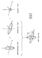
- Figure 1 represents such a confocal theta microscope with the angle ⁇ unequal 0 between the axes for illuminating the sample and for Detection of the emitted light.
- the lighting takes place along the z axis, and the resulting PSF is in extended in this direction. In the same way it is Detection PSF extended along the x axis. Both PSFs overlap in the area of the common focus. Only in This overlap area illuminates points and theirs Emission detected. If the angle ⁇ between the lighting and the detection axis is 90 °, is the overlapping area almost spherical, which means that the resolution is comparable in all three spatial directions. The extension of the total PSF resulting from the product of lighting and Detection PSFs are reduced to a minimum, what synonymous with an improved microscope resolution is.
- the interference of this the two rays reduce the full width at half maximum of the main maximum the lighting PSF.
- the 4Pi (B) confocal The technique called microscopy creates the interference the detection aperture and thus reduces the expansion of the Detection PSF. Called the 4Pi (C) confocal microscopy Method combines these two techniques.
- the sample is as in illuminated with a 4Pi (A) confocal microscope and the emitted Light orthogonal as in a confocal theta microscope detected so that the axial secondary maxima of the PSF are suppressed become. This means that the emission is outside the focal plane is not detected with 4Pi lighting.
- the illuminating light passes through the objective lens and forms the virtual focal point C i under the 45 ° mirror.
- the reflection on the mirror surface of the 45 ° mirror directs the light horizontally to the focal point C, which is located within the object to be observed.
- the detection optics only collect the light of the virtual image C d , which is formed by the horizontal mirror.
- the detection axis is therefore vertical, and the illumination and detection axes thus form an angle of 90 °.
- the alignment of the two mirror surfaces is chosen so that the images C i and C d of C lie in the focal plane of the lens and are confocally imaged in the illumination and detection optics.
- the beam path in a conventional confocal microscope must be changed in order to operate it as SLTM. These changes should preferably be made so that the Microscope still in conventional confocal mode can be operated. Especially for 4Pi lighting is a special modification of the lighting device necessary.
- the present invention shows a way how the changes on a conventional confocal microscope can be made.
- the invention proposes according to the features defined in claim 1, that the light with the help of a between lens and an image plane of the microscope located beam splitter or Reflector is coupled in and / or out and / or that the Coupling and / or decoupling takes place via optical fibers.
- a preferred embodiment of the microscope according to the invention is based on a Zeiss Axioplan universal microscope (Model 1), in which the reflector slide (between tube and Objective lens attached to the microscope) modified was that the coupling and uncoupling of the light with the device is possible by means of one or more optical fibers. In spite of additional slide parts are only modified, so that the original function of the Axioplan is preserved remains.
- the types of microscopy possible with this system are the following: 1) traditional wide field microscopy, 2) confocal Laser scanning microscopy (LSM) (through system modifications, which are not described here) 3) confocal theta microscopy and 4) 4Pi confocal theta microscopy. Both Theta microscopy is applied to spatial scanning to represent extensive structures.
- Figure 3 shows the lens, the theta mirror unit and the illumination and detection beam paths of the SLTM.
- a single objective lens focuses the illuminating and detection light on three points in the virtual image plane.
- This system differs from the embodiment in Figure 2 in that the theta mirror unit consists of three sections: a horizontal mirror R1 and two inclined mirrors R2 at angles ⁇ 1 and ⁇ 2 to the horizontal. This makes the sample optimally accessible from three different directions.
- the two outer ray paths are used for illumination so that 4Pi illumination can be achieved and the middle ray path is used for observation of the sample.
- NA is the numerical aperture of the lens and n r is the refractive index of the immersion medium.
- d w and ⁇ are as large as possible, but with standard lenses, the working distance decreases in many cases with the numerical aperture.
- theta mirror unit In order to fully specify the theta mirror unit, the following parameters must be defined: the distance w of the horizontal mirror from the focal plane BE; the distance L from the center of the mirror unit to the inner edge of the 45 ° mirror; the horizontal distance s from the inner edge of the 45 ° mirror to the central axis of the illumination beam path and the mirror height h .
- ⁇ 45 ° in Figure 3
- the parameter L stands for the shortest distance between the theta mirror unit and the focal point C and represents the greatest distance by which an object in the system can be scanned vertically.
- both virtual lighting focal points must lie in the focal plane in the field of view of the lens. If the distance between the virtual lighting focal points in the object plane is 4 L , their distance in the image plane is 4 M obj L , where M obj represents the magnification of the lens (see Figure 3). So that the microscope can display the two focal points simultaneously, the distance between the two focal points must be less than the field diameter ⁇ f , so that L ⁇ f / 4th M obj
- h c the maximum height at which the outer cone of light hits the surface of the 45 ° mirror (see Figure 3).
- the outputs of the two polarization-maintaining optical fibers are placed so that the laser light over the outer beam paths aimed at the object under observation can be (see Figure 3).
- a multimode optical fiber is in the central beam path and collects the scattered or fluorescent light of the object being observed.
- the standard mirror slide was used modified from an Axioplan microscope, which is located between the lens and the tube lens. He was advantageously changed so that one of its four openings used for the SLTM. It can also be one act different slider. Other microscope models exist also the possibility of attaching the optical fibers to the microscope stand to fix.
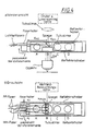
- Figure 4 shows a schematic representation of the mirror slide and the adjacent optics.
- the slider and the related components are in the front view and in the top view.
- Axioplan one of the four holes (A-D) in the slider, the side between the lens and the standard tube lens can. Then it either falls through the top part the eyepiece or through the rear aperture in the detection optics.
- Positions C and D work in the changed one System continues according to the principle just mentioned.
- B is for the Connection of the optical fibers used and A remains empty to the Do not block the beam path to the optical fibers. This empty position is used in the system's confocal LSM mode, where the light from the video port from the Axioplan is coupled in or out.
- the combination of the objective lens and that at position B of the Changes made by Slider preferably lead to a telecentric imaging system. This is structured that it is the light from the virtual focal points in the Lens focal plane collects and their enlarged images the optical fibers are projected on the image plane.
- d tm was set at 4.6 mm, so that d mf is 95.4 mm.
- the 63x lens used here has a focal length of 2.61 mm.
- the illuminating optical fibers for this work are, for example, Panda-type PP light guides (# WT-01-PGA-213-70C-005, WaveOptics Inc., Mountain View, CA, USA) with a field diameter of 3.5 ⁇ m, a cutoff wavelength of less than 470 nm and NA pp of 0.11.
- the lens is therefore over-illuminated, so that it can be assumed that the field is homogeneous over the entire rear focal plane.
- NA mm 0.22, 230 nm ⁇ ⁇ 1100 nm, 25 ⁇ m core, BTO Bungert GmbH, Weil der Stadt, Germany
- the exact positioning of the three fibers in the image plane of the Tube lens is for the successful operation of the SLTM from Meaning.
- the fibers must always be precise to each other and to Theta mirror device can be arranged.
- the MM optical fiber is directly on the modified mirror slide attached so that it serves as a fixed reference point.
- the theta mirror device can then be positioned on the basis of this reference point by operating the control elements for the xyz positioning on the microscope stage on which it rests.
- the PP optical fibers advantageously attached to translatory adjusting elements.
- the Fibers on three-axis piezoelectric position holders (Minitritor 3D MIN 38 NV, Piezsystem Jena GmbH, Jena, Germany) attached, which has a movement of 38 ⁇ m in each direction allow. These allow the lighting fibers to be spatially position relative to the MM fiber with nanometer accuracy. A rough adjustment of all three fibers can be done with Help the screws that hold the fibers to the mirror slide fix, be made.
- FIG. 5 shows a schematic diagram of the lighting and detection elements of the SLTM, which are located outside the microscope. The direction of light propagation is indicated by the arrows. The lighting beam paths are shown with continuous lines that correspond to the detection by dashed lines.
- the lasers are an argon ion laser (model 2014, Uniphase demos GmbH, Eching, Germany), which provides a line at 488 nm, and three HeNe lasers (models LHRP-1701, LHYP-0101, LHGP.0101, Research Electro-Optics, Inc., Boulder, Colorado, USA) for Wavelengths of 633, 594 and 543 nm. The entire arrangement is mounted on a vibration-isolated optical table.
- the light from the four lasers is transmitted through the dichroic mirrors dl-d3 bundled into a single beam, which is then in the AOM (Acoustic optical modulator: AA.AOTF.4C-T and AA.MOD.4C.230 VAC, A.A. Opto-Electronic, St.-Rémy-les-Chevreuse, France) is directed.
- AOM Acoustic optical modulator: AA.AOTF.4C-T and AA.MOD.4C.230 VAC, A.A. Opto-Electronic, St.-Rémy-les-Chevreuse, France
- the light beam coming from the AOM can either be directly in the first fiber coupler FC1 can be fed or through a Tilting mirror (Owis GmbH, Staufen i.Br., Germany) fm1 and the mirror m3 are redirected to the beam splitter.
- a Tilting mirror Olet al.
- fm1 is in the beam path brought and the beam of light coming from the AOM to the 50:50 non-polarizing beam splitter bs (broadband Hybrid cubic beam splitter 03 BSC 005, Melles Griot GmbH, Bensheim, Germany).
- the partial beams are over fc2 and fc3 coupled into fibers pp2 and pp3 (with fm2 OUT). These are used as lighting sources for the (4Pi-) confocal Theta microscopy is used
- the MM fiber mml is used with fm3 IN to the emitted Coupling out light from the Axioplan in confocal theta mode.
- the one emerging from this fiber (which ends at the separation adapter fc4)
- Light is collected through lens L (f / 1.25 mm Diameter, plane-convex, anti-reflective coating for visible light) and through mirrors m5 and fm3 (position ON) redirected to the filter wheel fw, which only the relevant Passes emission signals.
- What is urgent through this filter Light is emitted by the PMT (Photosensor module H5702-50, Hamamatsu Photonics Deutschland GmbH, Herrsching, Germany).
- fm1 is in the OUT position so that the laser light is transferred to the observation object via pp1.
- fm1, fm2 and fm3 are in the IN position. This makes it possible for the light is injected into pp2 and the signal is picked up by mml becomes. With fm2 IN and fm3 OUT, the light can also go out pp3 are directed into the PMT.
- the configuration for 4Pi confocal theta microscopy is similarly designed, except that fm2 is in the OUT position, so that both pp2 and pp3 are used as lighting sources can be.
- Laser scanning and detection optics are used at SLTM configuration not used.
- the sample is held by a capillary, which is attached to a precision scan table (model P-762.00, Physik Instrumente, Waldbronn, Germany), which has a range of motion of several millimeters and in all three directions over a range of 20 ⁇ m can be scanned with an accuracy of better than 40 nm.
- the capillary is aligned horizontally and inserted between the objective lens and the theta mirror unit to hold the object in position C (see Figure 3).
- the capillary is preferably rotated so that the observation object is below it and it blocks the beam path only minimally.
- the theta microscope is powered by an IBM PC compatible computer controlled, the cards for controlling the stepper motors in the Filter wheel, the DA converter (PCI-20098C, Burr-Brown / Intelligent Instrumentation, Arlington, USA) that drive the stage as well as the gain control for the PMT.
- ADC PCI-20098C, Burr-Brown / Intelligent Instrumentation, Arlington, USA
- the drives of the tilting mirrors and the piezo actuators for the fibers can over the Computers can be controlled, but also can not with the Computer connected and manually through the appropriate Drive units (PS1612 power supply, Monacor and E-101-01 Piezo control elements power supply, Piezosystem Jena GmbH) being controlled.
- a program written in Visual Basic manages the data acquisition.
- the computer generates three values for an xyz address that positions the observation object relative to the lens and the theta mirror unit.
- the positioning is controlled by an electronic component (model P-925.272, PI Physik Instrumente, Waldbronn, Germany), which works in a closed control loop.
- the intensity of the light emitted by the observation object is measured via a PMT as a function of the focus position in the object.
- the system can also be operated as a 4Pi confocal theta microscope become.
- This mode is very SLTM configuration Similar, with the exception that the object under observation is coherent is illuminated from at least two sides.
- the interference pattern, that of these two spreading in opposite directions Rays is designed to reduce the size of the lighting PSF and thus improves the resolution of the system.
- the best possible resolution is around 100 nm in 4Pi confocal Theta mode compared to 200-350 nm at the confocal Theta microscopy and approx. 1400 nm in confocal laser scanning mode.
- the distances d tm and d ot which define the position of the new tube lens, relate to the main planes of the lens and not to their physical dimensions.
- AOM Acoustic optical modulator bs beamsplitter d i dichroic mirror fc i fiber coupler fm i tilting mirror fw filter wheel L lens m i mirror mml Multimode optical fiber PMT Photomultiplier tube pp i polarization-maintaining optical fiber
Landscapes
- Physics & Mathematics (AREA)
- Chemical & Material Sciences (AREA)
- Analytical Chemistry (AREA)
- General Physics & Mathematics (AREA)
- Optics & Photonics (AREA)
- Microscoopes, Condenser (AREA)
Description
| C | Brennpunkt |
| Cd | virtueller Detektionsbrennpunkt |
| Ci | virtueller Beleuchtungsbrennpunkt |
| R1 | horizontaler Reflektor |
| R2 | schräger Reflektor |
| α | halber Öffnungswinkel des fokussierten Strahls |
| i | Neigungswinkel des Spiegels |
| ϑi | Winkel Theta |
| h | Höhe der Theta-Spiegeleinheit |
| hc | kritische Spiegelhöhe |
| L | horizontaler Abstand der Basis des schrägen Spiegels von der Mittelachse |
| s | horizontaler Abstand des Beleuchtungsbrennpunkts von der Basis des schrägen Spiegels |
| w | vertikaler Abstand des horizontalen Spiegels vom gemeinsamen Brennpunkt |
| dw | freier Arbeitsabstand |
| dmf | Anstand der Faser von der Tubuslinse |
| dtm | Abstand der Tubuslinse von dem Spiegel |
| dot | Abstand der Tubuslinse von dem Objektiv |
| xf | Abstand der Fasern voneinander |
| xmax | maximale Ausdehnung des beleuchteten Feldes auf dem Spiegel |
| AOM | Akusto-Optischer Modulator |
| bs | Strahlteiler |
| di | dichroitischer Spiegel |
| fci | Faserkoppler |
| fmi | Kippspiegel |
| fw | Filterrad |
| L | Linse |
| m i | Spiegel |
| mml | Multimode-Lichtleiterfaser |
| PMT | Photomultiplier Tube |
| ppi | polarisationserhaltende Lichtleiterfaser |
Claims (6)
- Lasermikroskop,dadurch gekennzeichnet,mit einer Objektivanordnung, durch die Beleuchtungslicht auf eine zu untersuchende Probe einfällt und die das zu registrierende Probenlicht aufnimmt, wobei die Detektionsrichtung in der Probe relativ zur Beleuchtungsrichtung um einen vorgegebenen Winkel geneigt ist,dass auf der probenabgewandten Seite der Objektivanordnung ein Schieber vorgesehen ist,dass der Schieber eine freie Durchgangsöffnung zur Verwendung des Mikroskops in einer ersten schieberstellung als Laserscanmikroskop aufweist,an den Schieber Lichtleitfasern angekoppelt sind und der Schieber ein Umlenkelement aufweist, welches in einer zweiten Schieberstellung das aus mindestens einer Beleuchtungslichtleitfaser austretende Beleuchtungslicht zu der Objektivanordnung und das aus der Objektivanordnung austretende Probenlicht zu mindestens einer Detektionslichtleitfaser richtet,
- Mikroskop nach Anspruch 1, dadurch gekennzeichnet, dass die Objektivanordnung als Doppelobjektv ausgebildet ist
- Mikroskop nach Anspruch 1 oder 2, dadurch gekennzeichnet, dass für die Theta-Mikroskopie zwei Beleuchtungslichtleitfasern vorgesehen sind, deren Beleuchtungslicht im Fokusbereich interferiert.
- Mikroskop nach einem der Ansprüche 1 bis 3, dadurch gekennzeichnet, dass die Lichtleitfasern piezoelektrisch justierbar sind.
- Mikroskop nach einem der Ansprüche 1 bis 5, dadurch gekennzeichnet, dass die Lichtleitfasern in Schieberichtung ausgerichtet sind und in einer Ebene liegen.
- Mikroskop nach einem der Ansprüche 1 bis 6, dadurch gekennzeichnet, dass die Objektivanordnung, eine Kollimationsoptik und die Lichtleitfasern ein telezentrisches Abbildungssystem bilden.
Applications Claiming Priority (3)
| Application Number | Priority Date | Filing Date | Title |
|---|---|---|---|
| DE19834279 | 1998-07-30 | ||
| DE19834279A DE19834279C2 (de) | 1998-07-30 | 1998-07-30 | Kompaktes Einzelobjektiv Theta-Mikroskop |
| PCT/EP1999/005372 WO2000007056A1 (de) | 1998-07-30 | 1999-07-27 | Konfokales theta-mikroskop |
Publications (2)
| Publication Number | Publication Date |
|---|---|
| EP1019769A1 EP1019769A1 (de) | 2000-07-19 |
| EP1019769B1 true EP1019769B1 (de) | 2004-09-29 |
Family
ID=7875791
Family Applications (1)
| Application Number | Title | Priority Date | Filing Date |
|---|---|---|---|
| EP99938354A Expired - Lifetime EP1019769B1 (de) | 1998-07-30 | 1999-07-27 | Konfokales theta-mikroskop |
Country Status (4)
| Country | Link |
|---|---|
| EP (1) | EP1019769B1 (de) |
| JP (1) | JP2002521733A (de) |
| DE (2) | DE19834279C2 (de) |
| WO (1) | WO2000007056A1 (de) |
Cited By (1)
| Publication number | Priority date | Publication date | Assignee | Title |
|---|---|---|---|---|
| US10983320B2 (en) | 2013-11-25 | 2021-04-20 | European Molecular Biology Laboratory | Optical arrangement for imaging a sample |
Families Citing this family (8)
| Publication number | Priority date | Publication date | Assignee | Title |
|---|---|---|---|---|
| DE10332073A1 (de) * | 2003-07-11 | 2005-02-10 | Carl Zeiss Jena Gmbh | Anordnung zur optischen Erfassung von in einer Probe angeregter und / oder rückgestreuter Lichtstrahlung mit Doppelobjektivanordnung |
| DE102005008619A1 (de) * | 2005-02-23 | 2006-09-07 | Leica Microsystems Cms Gmbh | Mikroskop und Detektormodul |
| DE102011054914A1 (de) * | 2011-10-28 | 2013-05-02 | Leica Microsystems Cms Gmbh | Verfahren und Anordnung zur Beleuchtung einer Probe |
| DE102012211943A1 (de) | 2012-07-09 | 2014-06-12 | Carl Zeiss Microscopy Gmbh | Mikroskop |
| DE102013213781A1 (de) * | 2013-03-20 | 2014-09-25 | Leica Microsystems Cms Gmbh | Verfahren und optische Anordnung zum Manipulieren und Abbilden einer mikroskopischen Probe |
| GB201315248D0 (en) * | 2013-08-28 | 2013-10-09 | Univ Singapore | Imaging |
| DE102013226277A1 (de) * | 2013-12-17 | 2015-06-18 | Leica Microsystems Cms Gmbh | Verfahren und Vorrichtung zum Untersuchen einer Probe mittels optischer Projektionstomografie |
| EP4235255B1 (de) | 2014-04-08 | 2026-05-06 | European Molecular Biology Laboratory | Optische anordnung und verfahren zur abbildung einer probe |
Family Cites Families (11)
| Publication number | Priority date | Publication date | Assignee | Title |
|---|---|---|---|---|
| US3013567A (en) * | 1953-03-10 | 1961-12-19 | Rooted Hair Inc | Method of stitching strands of simulated hair to a workpiece and of brushing aside loose ends of hair |
| EP0418928B1 (de) * | 1989-09-22 | 1996-05-01 | Fuji Photo Film Co., Ltd. | Rastermikroskop und Rastermechanismus dafür |
| DE4040441A1 (de) * | 1990-12-18 | 1992-07-02 | Hell Stefan | Doppelkonfokales rastermikroskop |
| DE4323129C2 (de) * | 1992-07-24 | 2002-10-02 | Zeiss Carl | Inverses Mikroskop |
| DE4326473C2 (de) * | 1993-08-06 | 1997-05-15 | European Molecular Biology Lab Embl | Konfokales Mikroskop |
| DE4404286C2 (de) * | 1994-02-11 | 1996-01-25 | Leica Mikroskopie & Syst | Fluoreszenzeinrichtung für ein Invers-Mikroskop |
| DE19529788B4 (de) * | 1994-08-30 | 2004-11-04 | Carl Zeiss | Zwischentubus für ein Mikroskop mit einer konfokalen Blendenscheibe |
| EP0718656B1 (de) * | 1994-12-23 | 1999-09-08 | Koike Seiki Co., Ltd. | Konfokales Durchlichtlasermikroskop |
| EP0842412A1 (de) * | 1995-08-01 | 1998-05-20 | Medispectra Inc. | Optische mikrosonden und verfahren zur spektralanalyse von materialien |
| DE19629725C2 (de) * | 1996-07-23 | 1998-09-17 | Europ Lab Molekularbiolog | Doppelobjektiv-System für ein Mikroskop, insbesondere Rastermikroskop |
| DE19632040C2 (de) * | 1996-08-08 | 1999-11-18 | Europ Lab Molekularbiolog | Konfokales Mikroskop |
-
1998
- 1998-07-30 DE DE19834279A patent/DE19834279C2/de not_active Expired - Fee Related
-
1999
- 1999-07-27 WO PCT/EP1999/005372 patent/WO2000007056A1/de not_active Ceased
- 1999-07-27 EP EP99938354A patent/EP1019769B1/de not_active Expired - Lifetime
- 1999-07-27 DE DE59910649T patent/DE59910649D1/de not_active Expired - Lifetime
- 1999-07-27 JP JP2000562790A patent/JP2002521733A/ja active Pending
Cited By (1)
| Publication number | Priority date | Publication date | Assignee | Title |
|---|---|---|---|---|
| US10983320B2 (en) | 2013-11-25 | 2021-04-20 | European Molecular Biology Laboratory | Optical arrangement for imaging a sample |
Also Published As
| Publication number | Publication date |
|---|---|
| EP1019769A1 (de) | 2000-07-19 |
| HK1031766A1 (en) | 2001-06-22 |
| DE19834279A1 (de) | 2000-03-02 |
| JP2002521733A (ja) | 2002-07-16 |
| DE19834279C2 (de) | 2002-09-26 |
| WO2000007056A1 (de) | 2000-02-10 |
| DE59910649D1 (de) | 2004-11-04 |
Similar Documents
| Publication | Publication Date | Title |
|---|---|---|
| EP0977069B2 (de) | Verfahren und Anordnung zur konfokalen Mikroskopie | |
| DE102011055294B4 (de) | Mikroskopische Einrichtung und Verfahren zur dreidimensionalen Lokalisierung von punktförmigen Objekten in einer Probe | |
| EP0866993B1 (de) | Konfokales mikroskop mit einem doppelobjektiv-system | |
| DE10105391A1 (de) | Scanmikroskop und Modul für ein Scanmikroskop | |
| DE10229935A1 (de) | Einrichtung zur Einkopplung von Licht in ein Mikroskop | |
| DE102012203736A1 (de) | Lichtrastermikroskop mit spektraler Detektion | |
| DE10340964A1 (de) | Lichtquelle mit einem mikrostrukturierten optischen Element | |
| DE102012020877A1 (de) | Optikanordnung und Lichtmikroskop | |
| WO2008098875A1 (de) | Mikroskop zur herkömmlichen fluoreszenzmikroskopie und zur totalinternen-reflexions-mikroskopie | |
| DE102006034906A1 (de) | Laser-Scanning-Mikroskop und Verfahren zu seinem Betrieb | |
| EP1678545B1 (de) | Mikroskop mit evaneszenter probenbeleuchtung | |
| EP2465001A1 (de) | Mikroskop zur messung von totalreflexions-fluoreszenz | |
| DE10118463A1 (de) | Verfahren und Anordnung zur tiefenaufgelösten optischen Erfassung einer Probe | |
| WO2018234582A2 (de) | Mikroskopsystem mit lichtblattmikroskopischer funktionseinheit | |
| DE19834279C2 (de) | Kompaktes Einzelobjektiv Theta-Mikroskop | |
| EP3066511B1 (de) | Mikroskop für evaneszente beleuchtung und punktförmige rasterbeleuchtung | |
| EP2122404B1 (de) | Konfokales lasermikroskop | |
| EP1281997A2 (de) | Scanmikroskop und optisches Element | |
| EP1697781A1 (de) | Objektiv zur evaneszenten beleuchtung und mikroskop | |
| WO2006000563A1 (de) | Mikroskop | |
| DE10031458B4 (de) | Scan-Mikroskop mit einem Zirkulator | |
| EP3516440B2 (de) | Mikroskopsystem | |
| EP1690122B1 (de) | Beleuchtungsmodul zur evaneszenten beleuchtung und mikroskop | |
| DE102006034914A1 (de) | Verfahren und Anordnung zur Ansteuerung eines Mikroskops, insbesondere eines Laser-Scanning-Mikroskopes | |
| DE102006034910B4 (de) | Mikroskop umfassend einen Strahlvereiniger |
Legal Events
| Date | Code | Title | Description |
|---|---|---|---|
| PUAI | Public reference made under article 153(3) epc to a published international application that has entered the european phase |
Free format text: ORIGINAL CODE: 0009012 |
|
| 17P | Request for examination filed |
Effective date: 20000311 |
|
| AK | Designated contracting states |
Kind code of ref document: A1 Designated state(s): AT BE CH CY DE DK ES FI FR GB GR IE IT LI LU MC NL PT SE |
|
| 17Q | First examination report despatched |
Effective date: 20030805 |
|
| GRAJ | Information related to disapproval of communication of intention to grant by the applicant or resumption of examination proceedings by the epo deleted |
Free format text: ORIGINAL CODE: EPIDOSDIGR1 |
|
| GRAP | Despatch of communication of intention to grant a patent |
Free format text: ORIGINAL CODE: EPIDOSNIGR1 |
|
| RBV | Designated contracting states (corrected) |
Designated state(s): DE GB |
|
| GRAS | Grant fee paid |
Free format text: ORIGINAL CODE: EPIDOSNIGR3 |
|
| GRAA | (expected) grant |
Free format text: ORIGINAL CODE: 0009210 |
|
| AK | Designated contracting states |
Kind code of ref document: B1 Designated state(s): DE GB |
|
| REG | Reference to a national code |
Ref country code: GB Ref legal event code: FG4D Free format text: NOT ENGLISH |
|
| REG | Reference to a national code |
Ref country code: IE Ref legal event code: FG4D Free format text: GERMAN |
|
| REF | Corresponds to: |
Ref document number: 59910649 Country of ref document: DE Date of ref document: 20041104 Kind code of ref document: P |
|
| GBT | Gb: translation of ep patent filed (gb section 77(6)(a)/1977) | ||
| REG | Reference to a national code |
Ref country code: IE Ref legal event code: FD4D |
|
| REG | Reference to a national code |
Ref country code: HK Ref legal event code: GR Ref document number: 1031766 Country of ref document: HK |
|
| PLBE | No opposition filed within time limit |
Free format text: ORIGINAL CODE: 0009261 |
|
| STAA | Information on the status of an ep patent application or granted ep patent |
Free format text: STATUS: NO OPPOSITION FILED WITHIN TIME LIMIT |
|
| 26N | No opposition filed |
Effective date: 20050630 |
|
| REG | Reference to a national code |
Ref country code: DE Ref legal event code: R081 Ref document number: 59910649 Country of ref document: DE Owner name: CARL ZEISS MICROSCOPY GMBH, DE Free format text: FORMER OWNER: CARL ZEISS JENA GMBH, 07745 JENA, DE Effective date: 20130206 |
|
| PGFP | Annual fee paid to national office [announced via postgrant information from national office to epo] |
Ref country code: DE Payment date: 20160129 Year of fee payment: 17 |
|
| PGFP | Annual fee paid to national office [announced via postgrant information from national office to epo] |
Ref country code: GB Payment date: 20160129 Year of fee payment: 17 |
|
| REG | Reference to a national code |
Ref country code: DE Ref legal event code: R119 Ref document number: 59910649 Country of ref document: DE |
|
| GBPC | Gb: european patent ceased through non-payment of renewal fee |
Effective date: 20160727 |
|
| PG25 | Lapsed in a contracting state [announced via postgrant information from national office to epo] |
Ref country code: DE Free format text: LAPSE BECAUSE OF NON-PAYMENT OF DUE FEES Effective date: 20170201 |
|
| PG25 | Lapsed in a contracting state [announced via postgrant information from national office to epo] |
Ref country code: GB Free format text: LAPSE BECAUSE OF NON-PAYMENT OF DUE FEES Effective date: 20160727 |