EP1019274B1 - Verfahren zum aufbringen definierter betätigungskräfte - Google Patents
Verfahren zum aufbringen definierter betätigungskräfte Download PDFInfo
- Publication number
- EP1019274B1 EP1019274B1 EP98959789A EP98959789A EP1019274B1 EP 1019274 B1 EP1019274 B1 EP 1019274B1 EP 98959789 A EP98959789 A EP 98959789A EP 98959789 A EP98959789 A EP 98959789A EP 1019274 B1 EP1019274 B1 EP 1019274B1
- Authority
- EP
- European Patent Office
- Prior art keywords
- act
- actuator
- torque
- brake
- signal
- Prior art date
- Legal status (The legal status is an assumption and is not a legal conclusion. Google has not performed a legal analysis and makes no representation as to the accuracy of the status listed.)
- Expired - Lifetime
Links
- 238000000034 method Methods 0.000 title claims description 48
- 230000006978 adaptation Effects 0.000 claims description 18
- 230000008569 process Effects 0.000 claims description 16
- 230000005484 gravity Effects 0.000 claims description 6
- 238000011144 upstream manufacturing Methods 0.000 claims description 5
- 230000005540 biological transmission Effects 0.000 description 12
- 230000033001 locomotion Effects 0.000 description 10
- 238000010586 diagram Methods 0.000 description 9
- 230000001133 acceleration Effects 0.000 description 7
- 238000013461 design Methods 0.000 description 4
- 230000005284 excitation Effects 0.000 description 4
- 230000008901 benefit Effects 0.000 description 3
- 238000012937 correction Methods 0.000 description 3
- 230000000694 effects Effects 0.000 description 3
- 230000003068 static effect Effects 0.000 description 3
- 230000033228 biological regulation Effects 0.000 description 2
- 238000011156 evaluation Methods 0.000 description 2
- 238000005259 measurement Methods 0.000 description 2
- 238000012935 Averaging Methods 0.000 description 1
- 238000013459 approach Methods 0.000 description 1
- 230000008859 change Effects 0.000 description 1
- 230000003750 conditioning effect Effects 0.000 description 1
- 230000007423 decrease Effects 0.000 description 1
- 238000011161 development Methods 0.000 description 1
- 230000007274 generation of a signal involved in cell-cell signaling Effects 0.000 description 1
- 230000006872 improvement Effects 0.000 description 1
- 230000010354 integration Effects 0.000 description 1
- 238000012544 monitoring process Methods 0.000 description 1
- 230000010355 oscillation Effects 0.000 description 1
- 238000012545 processing Methods 0.000 description 1
- 230000000630 rising effect Effects 0.000 description 1
- 230000001360 synchronised effect Effects 0.000 description 1
Images


Classifications
-
- B—PERFORMING OPERATIONS; TRANSPORTING
- B60—VEHICLES IN GENERAL
- B60T—VEHICLE BRAKE CONTROL SYSTEMS OR PARTS THEREOF; BRAKE CONTROL SYSTEMS OR PARTS THEREOF, IN GENERAL; ARRANGEMENT OF BRAKING ELEMENTS ON VEHICLES IN GENERAL; PORTABLE DEVICES FOR PREVENTING UNWANTED MOVEMENT OF VEHICLES; VEHICLE MODIFICATIONS TO FACILITATE COOLING OF BRAKES
- B60T13/00—Transmitting braking action from initiating means to ultimate brake actuator with power assistance or drive; Brake systems incorporating such transmitting means, e.g. air-pressure brake systems
- B60T13/74—Transmitting braking action from initiating means to ultimate brake actuator with power assistance or drive; Brake systems incorporating such transmitting means, e.g. air-pressure brake systems with electrical assistance or drive
Definitions
- the invention relates to a method for applying defined actuation forces a brake which can be actuated electrically by means of an actuator via a transmission, in which when the brake is tensioned, a first relationship between the actuator position and there is a second relationship when the brake is released exists between the actuator position and the actuator torque, as well as control systems to carry out the procedure.
- Such a method is e.g. from the German utility model DE 296 22 787 Ul known.
- a characteristic curve the controlled between the to be fed to the actuator Represents motor current and the actuating force to be expected for this motor current, queried by means of an electronic control device such that the desired Actuating force the corresponding current value is assigned.
- the determination of the Actuating force actual value are used by wheel sensors, the characteristic curve being changeable, see above that the stored relationship between motor current and actuating force actual context can be adjusted.
- the method for carrying out the known method is less advantageous view necessary use of the wheel sensors, their signals through drift and Offset can be disturbed. For this reason, the previously known method is unreliable and its implementation necessary.
- the actuator moments are used to specify the concept of the invention same actuator positions evaluated.
- the brake is additionally activated is controlled in such a way that an actuator torque passes through the actuator position surface e.g. if the brake actuation signal is sinusoidal or cosine Control signal is superimposed.
- the brake model reflects the rigidity or the efficiency of the brake.
- the actuator torque can be calculated either from one or more of the variables motor current I Akt , motor voltage U Akt and motor position ⁇ Akt .
- the motor position ⁇ Akt must be measurable (given the design of many motor types, eg electronically commutated synchronous motor, switched reluctance motor) or it must be possible to reconstruct it from the motor current I Akt and the motor voltage U Akt .
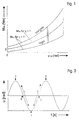
- Fig. 1 the basic course of the actuator torque M Act is plotted against the actuator position ⁇ Akt.
- the actuator torque values for quasi-static application acceleration ⁇ Akt so low that moments of inertia J and mass m are negligible
- a corresponding static moment M Akt, stat can be determined from the measured actuator torque M Akt, dyn via the inertias and the acceleration ( ⁇ ⁇ Akt ).
- v is a factor taking into account the ratio of the gearbox connected between the actuator and the brake.
- the absolute value of the dry friction is independent of the direction of rotation due to the design of the components subject to friction (bearings, e.g. ball bearings, barrel bearings etc. as well as spindle drives, e.g. roller screw drives).
- the design of the measuring method or the excitation determines to what extent subsequent correction calculations or additional identification procedures are necessary.
- the measurement duration should be as short as possible. However, it must be at least one period, which limits the usable frequency result. It must also be ensured that the procedure only is started with an approximately constant driver request and that with a strong change of the setpoint specified by the driver, the method is stopped so that the actual braking force follows the setpoint again.
- the proposed method allows the Estimate the efficiency or the actuation force of electric brakes. The estimate stands however not continuously available.
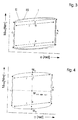
- the point A (Fig. 2) is the maximum vibration and thus also an inversion point Move. It is mapped in an area in the torque position diagram in FIG. 3, because by reversing the direction of motion, the friction torque also has its sign changes and thus a jump occurs in the actuator torque. That to maintain the Actuator torque required is reduced, because from this point it stops the friction the return of the brake and thus supports the holding of the position or Operating force.
- the falling edge 1 is also mapped into an area.
- the actuator torque increases with the position because the counter-torque that results from the clamping force. sinks (Spring characteristic).
- the rising edge (denoted by 2 in FIG. 2) is mapped into an area.
- the required torque also increases in proportion to the increase in position, since the Tension increases with the way and this connection for the small ones considered Changes around an operating point can be assumed to be linear.
- Point E in FIG. 2 again corresponds to point A. The cycle thus begins anew.
- Area 1 is slightly arched downwards because of the viscous friction of the backward movement inhibits the transmission, so less actuator torque to hold the predetermined Actuating force is necessary.
- the extreme of the curvature lies at point B, because there is also the maximum speed.
- Area 2 is curved upwards because the sign of the speed is positive here, that is the viscous friction in addition to the counter moment resulting from the actuating force, must be overcome by the actuator.
- the extreme of the curvature here is at point D, because the maximum speed for this movement section can be found here.
- the second derivative is also a sine. consequently the amount of acceleration is proportional to the deviation from the middle position.
- the behavior in area 1 is analogous.
- the actuator torque is reduced due to the inertia, since deceleration continues.
- the second half is an additional moment due to the onset of acceleration required.
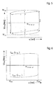
- this approach is obviously unsuitable in practice, since the estimate would be based on two isolated measured values and would therefore be extremely sensitive to interference. Different evaluation methods are therefore proposed.
- the method shown diagrammatically in FIG. 5 is very simple because it supports the Estimated value in turn only on two measured values.
- the curve is divided into an upper and a lower boundary line.
- the functions f above ( ⁇ Akt ) and f below ( ⁇ Akt) which represent these lines, are integrated, resulting in the areas F above and F below .
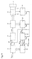
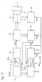
- the control circuit according to the invention shown in FIG. 9 for applying defined actuation forces essentially consists of a position controller 10, a position setpoint generator 11 connected upstream of the position controller 10, an electronic power unit 12 connected downstream of the position controller 10, a brake model adaptation module 13 and an estimation module 14.
- the electronic power unit 12, which is supplied with the output signal CMD (command manipulated variable) of the position controller 10, generates electrical output variables (for example, an actuator voltage U Akt and or an actuator current I Akt ) with which an actuator 15, which is only indicated schematically, is actuated, with the interposition a transmission 16 actuates an electromechanically actuated brake, which is provided with the reference number 17.
- the actuator 15 which is preferably formed by an electric motor, is preferably equipped with an angle measuring system 18, the signal of which corresponds to the actual actuator position is preferably fed to a position signal conditioning circuit 19, the output signal ⁇ Akt of a summation point 20, an actuator torque calculation module 21 and the previously mentioned estimation module 14 is provided.
- target position actuator is made of a one to ⁇ representing signal, and a control deviation ⁇ formed ⁇ the aforementioned signal Act Act, which serves as an input quantity of the position controller 10 degrees.
- the signal ⁇ soll is generated by the position setpoint generator 11, which contains a brake model and to which a signal F Bet, soll corresponding to an actuation force request is supplied.
- the actuator torque is calculated using actuator input variables supplied by the electronic power unit 12 and, if appropriate, the signal ⁇ Akt representing the actual actuator position.
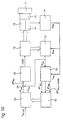
- the third control circuit shown in FIG. 11 has an actuating force controller 25, to which a control deviation ⁇ F Bet is supplied as an input variable, which, by subtracting a reconstructed actuating force signal F Bet, rek from the previously mentioned actuating force request signal F Bet, is intended in a third Summation point 27 is formed.
- the signal F Bet, rek corresponding to the reconstructed actuation force is preferably supplied by an actuation force reconstruction module 26 which contains the brake model and to which the actual actuator position signal ⁇ Akt and / or the actuator torque value M Akt determined in the actuator torque calculation module 21 are supplied as input variables.
- the brake model adaptation module 13 contains the model sizes calculated by means of parameter estimation.
- the brake model can preferably either map the rigidity of the brake 17 or its efficiency.
- a braking torque controller 28 is provided, to which a control deviation .DELTA.M B is supplied as an input variable, which by subtracting a signal M B, rek representing a reconstructed braking torque , from a desired braking torque signal M B, is intended in a fourth summation point 30 is formed.
- the signal M B, rek corresponding to the reconstructed braking torque is preferably supplied by a braking torque reconstruction module 29 which contains a relationship between the slip ⁇ rad occurring at the wheel and the associated braking torque and which is supplied with the signal ⁇ rad corresponding to the wheel slip and adapted characteristic quantities as input variables become.
- the adapted characteristic curve quantities are preferably generated in a characteristic curve adaptation module 31, to which the wheel slip signal ⁇ rad and an estimated actuation force value F * Bet, estimate are supplied, which is supplied by an estimation module 32 that is modified compared to the exemplary embodiments according to FIGS. 9 to 11 ,
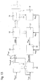
- the fifth control circuit according to FIG. 13 is characterized in that a slip controller 33 is provided, to which a control deviation ⁇ rad is supplied as an input variable, which is intended by subtracting the wheel slip signal ⁇ rad mentioned in connection with FIG. 12 from a wheel slip setpoint signal ⁇ rad is formed in a fifth summation point 35.
- the corresponding to the desired wheel slip signal ⁇ rad should be preferably provided by a slip regulator 33 upstream Radschlupfsollwertgenerator 34, the ⁇ a relationship between the occurring the wheel slip wheel and includes the corresponding braking torque or a this correlation representing characteristic and as input variables the braking torque request signal M B mentioned in connection with FIG. 12 is to be supplied as well as adapted characteristic curve quantities.
- the adapted characteristic curve quantities are generated in a characteristic curve adaptation module 31, to which the wheel slip signal ⁇ rad and the above-mentioned estimated actuation force value F * Bet are estimated.
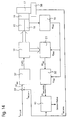
- the sixth control circuit shown in FIG. 14 has an actuating force controller 37, to which, similar to the embodiment shown in FIG. 11, the control deviation ⁇ F Bet is fed as an input variable, which was sensed by subtracting one on the brake 17 by means of an actuating force sensor 38
- Actuating force F Bet sens from the previously mentioned actuating force request signal F Bet, is to be formed in a sixth summation point 39.
- the signal F Bet sens corresponding to the sensed actuation force is also fed to an actuation force sensor monitoring module 40, to which the estimated actuation force value F * Bet, estimate mentioned in connection with FIGS. 12 and 13 is fed as a second input variable, and which monitors the actuation force sensor 38.
Description
ein Bremsenmodell-Adaptionsmodul vorgesehen ist, dem zur Adaption der dem Wirkungsgrad des Getriebes η=1 entsprechende Aktuatormomentwert, die die dazugehörigen Aktuatormomente aus einem oder beiden Zusammenhängen zwischen der Aktuatorposition und dem Aktuatormoment bzw. zwischen der Aktuatorposition und dem Aktuatormoment oder die die dazugehörige Aktuatorposition repräsentierenden Signale zugeführt werden und das Modellgrößen für ein Bremsenmodell erzeugt,
- Fig. 1
- eine diagrammatische Darstellung der Abhängigkeit des Aktuatormomentes von der Aktuatorposition bzw. der Arbeitsweise des erfindungsgemäßen Verfahrens;
- Fig. 2
- eine diagrammatische Darstellung des Zeitverlaufs der Aktuatorposition am Beispiel der Überlagerung des Betätigungssignals mit einem Sinussignal;
- Fig. 3 bis 8
- diagrammatische Darstellungen verschiedener Methoden zur Bestimmung des dem Wirkungsgrad des Getriebes η = 1 entsprechenden fiktiven Aktuatormomentes;
- Fig. 9 bis 13
- fünf Ausführungsbeispiele von zur Durchführung des erfindungsgemäßen Verfahrens verwendbaren Regelschaltungen.
- dges kann durch Identifikationsverfahren geschätzt werden. Dazu ist es zweckmäßig, die Bremse im gelüfteten Zustand (FBet = 0 also in Phasen, in denen die Bremse nicht vom Fahrer oder vom übergeordneten Regelsystem betätigt wird) dynamisch anzuregen, und dges mittels Parameterschätzung zu bestimmen.
- Es ist jedoch günstiger sicherzustellen, daß die Punkte gleicher Position bzw. gleicher Betätigungskraft beim Spannen und beim Lösen mit betragsmäßig gleicher Geschwindigkeit durchfahren werden. Dann wird der Term, mit dem dges multipliziert wird, zu Null und der Einfluß der viskosen Reibung wird ebenfalls mit sich selbst kompensiert. Dies kann man z.B. erreichen, indem man dem Aktuatorpositionssollsignal oder dem Betätigungskraftsollsignal einen Sinus mit kleiner Amplitude (vom Fahrer nicht spürbar) überlagert und so "Hysterezyklen" durchfährt (siehe Fig. 1). Die Geschwindigkeit ωAkt hat dann den Verlauf eines Cosinus, so daß sich an gleicher Aktuatorposition die gleiche Geschwindigkeit einstellt.


Claims (18)
- Verfahren zum Aufbringen definierter Betätigungskräfte bei einer mittels eines Aktuators über ein Getriebe elektrisch betätigbaren Bremse, bei dem beim Spannen der Bremse ein erster Zusammenhang zwischen der Aktuatorposition (ϕAkt) und dem Aktuatormoment (MAkt) besteht und beim Lösen der Bremse ein zweiter Zusammenhang zwischen der Aktuatorposition (ϕAkt) und dem Aktuatormoment (MAkt) besteht, dadurch gekennzeichnet, daß die sich aus dem ersten sowie dem zweiten Zusammenhang ergebenden Aktuatormomente (MAkt) zur Ermittlung des Wirkungsgrades (η) des Getriebes im Sinne der Ermittlung eines Aktuatormomentwertes (MAkt,η=1) ausgewertet werden, der beim Wirkungsgrad des Getriebes η=1 aufgebracht werden muß.
- Verfahren nach Anspruch 1, dadurch gekennzeichnet, daß die Aktuatormomente bei gleichen Aktuatorpositionen (ϕAkt) ausgewertet werden.
- Verfahren nach Anspruch 1 oder 2 dadurch gekennzeichnet, daß das Aktuatormoment aus dem Aktuatorstrom (IAkt) bzw. dem Aktuatorstrom (IAkt) und der Aktuatorspannung (UAkt) bzw. dem Aktuatorstrom (IAkt) und der Aktuatorposition (ϕAkt) bzw. der Aktuatorspannung (UAkt) und der Aktuatorposition (ϕAkt) bzw. dem Aktuatorstrom (IAkt), der Aktuatorspannung (UAkt) und der Aktuatorposition (ϕAkt) ermittelt wird.
- Verfahren nach Anspruch 3, dadurch gekennzeichnet, daß aus dem Aktuatormomentwert (MAkt,η=1) über die Getriebeübersetzung ein Schätzwert der Betätigungskraft (FBet,schätz) ermittelt wird.
- Verfahren nach einem der Ansprüche 1 bis 4, dadurch gekennzeichnet, daß eine einem Aktuatorpositionsbereich entsprechende, durch die beiden Zusammenhänge begrenzte Teilfläche ausgewertet wird.
- Verfahren nach Anspruch 5, dadurch gekennzeichnet, daß die Teilfläche derart ausgewertet wird, daß der Aktuatormomentwert (MAkt,η=1) durch Mittelung des maximalen und des minimalen Aktuatormomentes berechnet wird.
- Verfahren nach Anspruch 5, dadurch gekennzeichnet, daß die Teilfläche derart ausgewertet wird, daß der Aktuatormomentwert (MAkt,η=1) durch Berechnung der Ordinate der die Fläche halbierenden horizontalen Geraden bestimmt wird.
- Verfahren nach Anspruch 5, dadurch gekennzeichnet, daß die Teilfläche derart ausgewertet wird, daß die Aktuatormomente aus beiden Zusammenhängen bei jeweils gleicher Aktuatorposition gemittelt werden und durch die entstehenden Mittelwerte eine Ausgleichsgerade gelegt wird, deren Ordinate als Schätzwert für den Aktuatormentwert (MAkt,η=1) verwendet wird.
- Verfahren nach Anspruch 5, dadurch gekennzeichnet, daß die Teilfläche derart ausgewertet wird, daß der Schwerpunkt der Teilfläche berechnet wird und seine Ordinate als Schätzwert für den Aktuatormomentwert (MAkt,η=1) verwendet wird.
- Verfahren nach einem der Ansprüche 1 bis 9, dadurch gekennzeichnet, daß die Aktuatormomente vor der Ermittlung des Wirkungsgrades des Getriebes um die Trägheitsmomente der Bremse korrigiert werden.
- Verfahren nach einem der vorhergehenden Ansprüche, dadurch gekennzeichnet, daß die Bremse bei der Betätigung zusätzlich derart angesteuert wird, daß eine Aktuatorment-Aktuatorposition-Fläche durchfahren wird.
- Verfahren nach Anspruch 11, dadurch gekennzeichnet, daß dem Betätigungssignal der Bremse ein sinus- oder cosinusförmiges Ansteuersignal überlagert wird.
- Regelschaltung zum Aufbringen definierter Betätigungskräfte bei einer mittels eines Aktuators über ein Getriebe elektrisch betätigbaren Bremse, wobei beim Spannen der Bremse ein erster Zusammenhang zwischen der Aktuaterposition (ϕAkt) und dem Aktuatormoment (MAkt) besteht und beim Lösen der Bremse ein zweiter Zusammenhang zwischen der Aktuatorpositon (ϕAkt) und dem Aktuatormoment (MAkt) besteht, zur Durchführung des Verfahrens nach einem der Ansprüche 1 bis 12, dadurch gekennzeichnet, daßa) ein Lageregler (10) vorgesehen ist, dem als Eingangssignal die Regeldifferenz (ΔϕAkt) zwischen einem die Aktuator-Sollposition (ϕSoll) und einem die Aktuator-Istposition (ϕAkt) repräsentierenden Signalen zugeführt wird und mit dessen Ausgangssignal (CMD) der Aktuator (15) über eine elektronische Leistungseinheit (12) angesteuert wird,b) ein Bremsenmodell-Adaptionsmodul (13) vorgesehen ist, dem zur Adaption der dem Wirkungsgrad des Getriebes η=1 entsprechende Aktuatormomentwert (M*Akt,η=1,schatz), die die dazugehörigen Aktuatormomente (M*Akt) aus einem oder beiden Zusammenhängen zwischen der Aktuatorposition (ϕAkt) und dem Aktuatormoment (MAkt) bzw. zwischen der Aktuatorposition (ϕAkt) und dem Aktuatormoment (MAkt) oder die die dazugehörige Aktuatorposition (ϕ*Akt) repräsentierenden Signale zugeführt werden und das Modellgrößen für ein Bremsenmodell erzeugt,c) dem Lageregler (10) ein Lagesollwertgenerator (11) vorgeschaltet ist, der das Bremsenmodell beinhaltet und dem ein der gewünschten Betätigungskraft entsprechendes Signal (FBet,soll) sowie die adaptierten Modellgrößen zugeführt werden und der aus dem Bremsenmodell das Aktuator-Sollpositionssignal (ϕsoll) erzeugt,d) ein Schätzmodul (14) vorgesehen ist, dem das dem Aktuatormoment (MAkt) und das der Aktuatorposition (ϕAkt) entsprechende Signal zugeführt werden und das den dem Wirkungsgrad des Getriebes η=1 entsprechenden Aktuatormomentwert (M*Akt,η=1,schätz), die dazugehörigen Aktuatormomente (M*Akt) aus einem oder beiden Zusammenhängen zwischen der Aktuatorposition (ϕAkt)und dem Aktuatormoment (MAkt) bzw. zwischen der Aktuatorposition (ϕAkt) und dem Aktuatormoment (MAkt) oder die die dazugehörige Aktuatorposition (ω*Akt) repräsentierenden Signale erzeugt.
- Regelschaltung zum Aufbringen definierter Betätigungskräfte bei einer mittels eines Aktuators über ein Getriebe elektrisch betätigbaren Bremse, wobei beim Spannen der Bremse ein erster Zusammenhang zwischen der Aktuatorposition (ϕAkt) und dem Aktuatormoment (MAkt) besteht und beim Lösen der Bremse ein zweiter Zusammenhang zwischen der Aktuatorposition (ϕAkt) und dem Aktuatormoment (MAkt) besteht, zur Durchführung des Verfahrens nach einem der Ansprüche 1 bis 12 dadurch gekennzeichnet, daßa) ein Momentenregler (22) vorgesehen ist, dem als Eingangssignal die Regeldifferenz (ΔMAkt) zwischen einem das Aktuator-Sollmoment (Msoll) und einem das Aktuator-Istmoment (MAkt) repräsentierenden Signal zugeführt wird und mit dessen Ausgangssignal (CMD) der Aktuator (15) über eine elektronische Leistungseinheit (12) angesteuert wird,b) ein Bremsenmodell-Adaptionsmodul (13) vorgesehen ist, dem zur Adaption der dem Wirkungsgrad des Getriebes η=1 entsprechende Aktuatormomentwert (M*Akt,η=1,schätz), die die dazugehörigen Aktuatormomente (M* Akt) aus einem oder beiden Zusammenhängen zwischen der Aktuatorposition (ϕAkt) und dem Aktuatormoment (MAkt) bzw. zwischen der Aktuatorposition (ϕAkt) und dem Aktuatormoment (MAkt) oder die die dazugehörige Aktuatorposition (ϕ*Akt) repräsentierenden Signale zugeführt werden und das Modellgrößen für ein Bremsenmodell erzeugt,c) dem Momentenregler (22) ein Momentensollwertgenerator (23) vorgeschaltet ist, der das Bremsenmodell beinhaltet und dem ein der gewünschten Betätigungskraft entsprechendes Signal (FBet,soll) sowie die adaptierten Modellgrößen zugeführt werden und der aus dem Bremsenmodell das Aktuator-Sollmomentsignal (Msoll) erzeugt,d) ein Schätzmodul (14) vorgesehen ist, dem das dem Aktuatormoment (MAkt) und das der Aktuatorposition (ϕAkt) entsprechende Signal zugeführt werden und das dem Wirkungsgrad des Getriebes η=1 entsprechenden Aktuatormomentwert (M' Akt,η=1,schätz), das die dazugehörigen Aktuatormomente (M*Akt) aus einem oder beiden Zusammenhängen zwischen der Aktuatorposition (ϕAkt) und dem Aktuatormoment (MAkt) bzw. zwischen der Aktuatorposition (ϕAkt) und dem Aktuatormoment (MAkt) oder die die dazugehörige Aktuatorposition (ϕ*Akt) repräsentierenden Signale erzeugt.
- Regelschaltung zum Aufbringen definierter Betätigungskräfte bei einer mittels eines Aktuators über ein Getriebe elektrisch betätigbaren Bremse, wobei beim Spannen der Bremse ein erster Zusammenhang zwischen der Aktuatorposition (ϕAkt) und dem Aktuatormoment (MAkt) besteht und beim Lösen der Bremse ein zweiter Zusammenhang zwischen der Aktuatorposition (ϕAkt) und dem Aktuatormoment (MAkt) besteht, zur Durchführung des Verfahrens nach einem der Ansprüche 1 bis 12, dadurch gekennzeichnet, daßa) ein Betätigungsregler (25) vorgesehen ist, dem als Eingangssignal die Regeldifferenz (ΔFBet) zwischen einem den Betätigungskraft-Wunschwert (FBet,soll) und einem den rekonstruierten Betätigungskraft-Istwert (FBetk,rek) repräsentierenden Signalen zugeführt wird und mit dessen Ausgangssignal (CMD) der Aktuator (15) über eine elektronische Leistungseinheit (12) angesteuert wird,b) ein Bremsenmodell-Adaptionsmodul (13) vorgesehen ist, dem zur Adaption der dem Wirkungsgrad des Getriebes η=1 entsprechende Aktuatormomentwert (M*Akt,η=1,schatz) die die dazugehörigen Aktuatormomente (M*Akt) aus einem oder beiden Zusammenhängen zwischen der Aktuatorposition (ϕAkt) und dem Aktuatormoment (MAkt) bzw. zwischen der Aktuatorposition (ϕAkt) und dem Aktuatormoment (MAkt) oder die die dazugehörige Aktuatorposition (ϕ*Akt) repräsentierenden Signale zugeführt werden und das Modellgrößen für ein Bremsenmodell erzeugt,c) dem Betätigungskraftregler (25) ein Betätigungskraftrekonstruktionsmodul (26) vorgeschaltet ist, das das Bremsenmodell beinhaltet und dem ein das Aktuator-Istmoment (MAkt) oder ein die Aktuator-Istposition (ϕAkt) repräsentierendes Signal sowie die adaptierten Modellgrößen zugeführt werden und der aus dem Bremsenmodell den Betätigungskraft-Istwert (FBet,rek) erzeugt,d) ein Schätzmodul (14) vorgesehen ist, dem das dem Aktuatormoment (MAkt) und das der Aktuatorposition (ϕAkt) entsprechende Signal zugeführt werden und das den dem Wirkungsgrad des Getriebes η=1 entsprechenden Aktuatormomentwert (M*Akt,η=1,schätz), die die dazugehörigen Aktuatormomente (M'Akt) aus einem oder beiden Zusammenhängen zwischen der Aktuatorposition (ϕAkt) und dem Aktuatormoment (MAkt) bzw. zwischen der Aktuatorposition (ϕAkt) und dem Aktuatormoment (MAkt) oder die die dazugehörigen Aktuatorposition (ϕ*Akt) repräsentierenden Signale erzeugt.
- Regelschaltung nach einem der Ansprüche 13 bis 15, dadurch gekennzeichnet, daß das Bremsenmodell-Adaptionsmodul (13) die Bremsenmodellgrößen mittels Parameterschätzung berechnet.
- Regelschaltung nach Anspruch 13 oder 15, dadurch gekennzeichnet, daß das Bremsenmodell die Steifigkeit der Bremse (17) abbildet.
- Elektromechanisch betätigbare Bremse nach Anspruch 14 oder 15, dadurch gekennzeichnet, daß das Bremsenmodell den Wirkungsgrad der Bremse (17) abbildet.
Applications Claiming Priority (3)
| Application Number | Priority Date | Filing Date | Title |
|---|---|---|---|
| DE19742920A DE19742920A1 (de) | 1997-09-29 | 1997-09-29 | Verfahren zum Aufbringen definierter Betätigungskräfte |
| DE19742920 | 1997-09-29 | ||
| PCT/EP1998/006190 WO1999016650A1 (de) | 1997-09-29 | 1998-09-29 | Verfahren zum aufbringen definierter betätigungskräfte |
Publications (2)
| Publication Number | Publication Date |
|---|---|
| EP1019274A1 EP1019274A1 (de) | 2000-07-19 |
| EP1019274B1 true EP1019274B1 (de) | 2003-06-04 |
Family
ID=7843968
Family Applications (1)
| Application Number | Title | Priority Date | Filing Date |
|---|---|---|---|
| EP98959789A Expired - Lifetime EP1019274B1 (de) | 1997-09-29 | 1998-09-29 | Verfahren zum aufbringen definierter betätigungskräfte |
Country Status (5)
| Country | Link |
|---|---|
| US (1) | US6435625B1 (de) |
| EP (1) | EP1019274B1 (de) |
| JP (1) | JP4383654B2 (de) |
| DE (2) | DE19742920A1 (de) |
| WO (1) | WO1999016650A1 (de) |
Cited By (2)
| Publication number | Priority date | Publication date | Assignee | Title |
|---|---|---|---|---|
| DE102013109415A1 (de) | 2013-08-29 | 2015-03-05 | Fev Gmbh | Verfahren zur Ermittlung eines Reibmoments einer Getriebekomponente sowie Vorrichtung zur Ermittlung eines Reibmoments einer Getriebekomponente |
| DE102018222030A1 (de) * | 2018-12-18 | 2020-06-18 | Zf Friedrichshafen Ag | Verfahren zur Ermittlung eines Verlustmoments eines Getriebes |
Families Citing this family (33)
| Publication number | Priority date | Publication date | Assignee | Title |
|---|---|---|---|---|
| US6132016A (en) * | 1997-05-02 | 2000-10-17 | Hydro-Aire, Inc. | System and method for adaptive brake application and initial skid detection |
| US6722745B2 (en) * | 1997-05-02 | 2004-04-20 | Hydro-Aire, Inc. | System and method for adaptive brake application and initial skid detection |
| WO2000047458A1 (de) | 1999-02-11 | 2000-08-17 | Continental Teves Ag & Co. Ohg | Verfahren und vorrichtung zur ermittlung einer in der aufstandsfläche eines rades eines fahrzeugs wirkenden bremskraft |
| DE19954198B4 (de) * | 1999-02-11 | 2011-08-18 | Continental Teves AG & Co. OHG, 60488 | Verfahren und Vorrichtung zur Ermittlung einer in der Aufstandsfläche eines Rades eines Fahrzeugs wirkenden Bremskraft |
| US6550871B1 (en) | 1999-02-19 | 2003-04-22 | Continental Teves, Inc. | Method and system for controlling an electromechanically actuated brake for motor vehicles |
| DE19925607A1 (de) * | 1999-02-19 | 2000-08-24 | Continental Teves Ag & Co Ohg | Verfahren und System zur Ansteuerung einer elektromechanisch betätigbaren Bremse für Kraftfahrzeuge |
| US6848756B2 (en) | 2000-03-15 | 2005-02-01 | Continental Teves Ag & Co., Ohg | Method and control system for applying defined clamping forces |
| DE10049526C2 (de) * | 2000-10-06 | 2003-03-06 | Bosch Gmbh Robert | Emulationsmodul zur Generierung von Signalen zur Erfassung von Fahrsituationen |
| DE10056549C2 (de) * | 2000-11-15 | 2003-11-06 | Bosch Gmbh Robert | Mehrfachnutzung von Sensorsignalen durch mehrere Fahrzeugsysteme |
| WO2002088562A1 (de) * | 2001-04-26 | 2002-11-07 | Knorr-Bremse Systeme für Nutzfahrzeuge GmbH | Scheibenbremse mit elektromotorisch angetriebenem verschleissnachstellsystem |
| DE10123568A1 (de) * | 2001-05-15 | 2002-11-21 | Continental Teves Ag & Co Ohg | Verfahren und System zur Ansteuerung einer elektromechanisch betätigbaren Bremse für Kraftfahrzeuge |
| WO2003011668A1 (de) * | 2001-07-31 | 2003-02-13 | Continental Teves Ag & Co. Ohg | Verfahren zur ermittlung des zusammenhangs zwischen aktuatorposition und aktuatorzuspannkraft |
| WO2003016745A2 (de) | 2001-08-16 | 2003-02-27 | Wabco Gmbh & Co.Ohg | Zuspanneinrichtung für eine bremse |
| US6913327B2 (en) * | 2002-06-20 | 2005-07-05 | Delphi Technologies, Inc. | Method and apparatus for control of a motor-driven brake actuator |
| US7448701B2 (en) * | 2003-09-26 | 2008-11-11 | Haldex Brake Products Ab | System for control of brake actuator based at least in part upon tire/road friction force |
| DE10361042B3 (de) | 2003-12-23 | 2005-05-25 | Lucas Automotive Gmbh | Feststellbremse und Verfahren zur Steuerung derselben |
| DE102005011267A1 (de) * | 2004-04-17 | 2006-03-30 | Continental Teves Ag & Co. Ohg | Verfahren und Regelsystem zum Aufbringen definierter Spannkräfte |
| DE102004059688A1 (de) * | 2004-12-10 | 2006-06-14 | Siemens Ag | Verfahren zur Betätigung einer Feststellbremsanlage für Fahrzeuge |
| EP1746399A1 (de) * | 2005-07-22 | 2007-01-24 | Delphi Technologies, Inc. | Abschätzung der Kraft/Drehmoment, der gegen einen electromotorischen Stellantrieb von einer Last ausgeübt wird |
| JP4618035B2 (ja) * | 2005-07-27 | 2011-01-26 | 株式会社アドヴィックス | 車両走行制御装置 |
| JP4834397B2 (ja) * | 2005-12-15 | 2011-12-14 | 日立オートモティブシステムズ株式会社 | 車両のブレーキ制御装置 |
| EP1800809A1 (de) * | 2005-12-19 | 2007-06-27 | ABB Technology AG | Bremsvorrichtung für einen Roboterantrieb und Verfahren zum Erkennen eines Bremsenzustandes |
| DE102006052810B4 (de) | 2006-11-09 | 2021-09-02 | Robert Bosch Gmbh | Verfahren zur Abschätzung einer Kraftentfaltung eines an eine Versorgungsspannung anschließbaren Aktuators |
| FR2908718B1 (fr) * | 2006-11-22 | 2009-10-02 | Jean Marc Loriot | Dispositif de commande d'un actionneur electrique de frein |
| JP5104370B2 (ja) * | 2008-02-13 | 2012-12-19 | 株式会社アドヴィックス | 駐車ブレーキ制御装置 |
| DE102010039309B4 (de) * | 2010-08-13 | 2023-03-30 | Robert Bosch Gmbh | Verfahren zur Ermittlung des Wirkungsgrades einer elektrisch betätigbaren Feststellbremse in einem Fahrzeug |
| DE102011003183A1 (de) * | 2011-01-26 | 2012-07-26 | Robert Bosch Gmbh | Verfahren zur Überwachung der Funktion einer Feststellbremse in einem Fahrzeug |
| JP6080682B2 (ja) | 2013-05-17 | 2017-02-15 | Ntn株式会社 | 電動式直動アクチュエータおよび電動ブレーキ装置 |
| US9610927B2 (en) * | 2015-06-26 | 2017-04-04 | Goodrich Corporation | Systems and methods for electric brake force estimation tolerant to drivetrain stiction |
| JP6527789B2 (ja) * | 2015-08-21 | 2019-06-05 | Ntn株式会社 | 電動ブレーキ装置 |
| AT522040B1 (de) | 2018-12-17 | 2020-11-15 | Greenbrakes Gmbh | Elektromechanische Bremsenanlage |
| DE102021201046A1 (de) | 2021-02-04 | 2022-08-04 | Continental Teves Ag & Co. Ohg | Verfahren zur Steuerung eines Bremssystems |
| DE102021214096A1 (de) | 2021-12-10 | 2023-06-15 | Continental Automotive Technologies GmbH | Verfahren zum Überwachen einer elektrisch betätigten Bremse und Bremsenanordnung |
Family Cites Families (12)
| Publication number | Priority date | Publication date | Assignee | Title |
|---|---|---|---|---|
| DE3603810A1 (de) * | 1986-02-07 | 1987-08-13 | Bosch Gmbh Robert | Regeleinrichtung |
| DE4317846A1 (de) | 1993-05-28 | 1994-12-01 | Wabco Vermoegensverwaltung | Verfahren zur Einstellung eines Bremswertes auf einen Soll-Bremswert |
| US5366280A (en) * | 1994-02-14 | 1994-11-22 | General Motors Corporation | Method of adaptively homing brake actuators |
| GB9420192D0 (en) * | 1994-10-06 | 1994-11-23 | Lucas Ind Plc | Improvements in hydraulic braking systems of the brake-by-wire type |
| DE19621671A1 (de) * | 1996-05-30 | 1997-12-04 | Bosch Gmbh Robert | Verfahren und Vorrichtung zur Ermittlung der Koppelkräfte innerhalb eines Wagenzuges |
| DE29622787U1 (de) | 1996-07-09 | 1997-06-12 | Continental Ag | Elektrische Bremsanlage für ein Kraftfahrzeug |
| DE19639686A1 (de) * | 1996-09-26 | 1998-04-16 | Siemens Ag | Bremsanlage für ein Kraftfahrzeug |
| FR2753948B1 (fr) * | 1996-10-01 | 2003-04-11 | Bosch Gmbh Robert | Procede et dispositif pour commander une installation de freins d'un vehicule |
| JP3837195B2 (ja) * | 1996-12-26 | 2006-10-25 | 曙ブレーキ工業株式会社 | パッドクリアランス調整機構を備えた電動ブレーキとそのパッドクリアランス調整法 |
| EP1032520B1 (de) * | 1997-11-22 | 2002-05-08 | Continental Teves AG & Co. oHG | Verfahren und system zur ansteuerung einer elektromechanisch betätigbaren feststellbremse für kraftfahrzeuge |
| US6036285A (en) * | 1997-12-31 | 2000-03-14 | The B.F. Goodrich Company | Brake system using torque feedback control with torque level transitioning |
| US6178369B1 (en) * | 1998-01-30 | 2001-01-23 | Continental Teves Ag & Co., Ohg | Method and regulating system for applying defined actuating forces |
-
1997
- 1997-09-29 DE DE19742920A patent/DE19742920A1/de not_active Withdrawn
-
1998
- 1998-09-29 EP EP98959789A patent/EP1019274B1/de not_active Expired - Lifetime
- 1998-09-29 DE DE59808654T patent/DE59808654D1/de not_active Expired - Lifetime
- 1998-09-29 JP JP2000513752A patent/JP4383654B2/ja not_active Expired - Lifetime
- 1998-09-29 WO PCT/EP1998/006190 patent/WO1999016650A1/de active IP Right Grant
- 1998-09-29 US US09/509,727 patent/US6435625B1/en not_active Expired - Fee Related
Cited By (2)
| Publication number | Priority date | Publication date | Assignee | Title |
|---|---|---|---|---|
| DE102013109415A1 (de) | 2013-08-29 | 2015-03-05 | Fev Gmbh | Verfahren zur Ermittlung eines Reibmoments einer Getriebekomponente sowie Vorrichtung zur Ermittlung eines Reibmoments einer Getriebekomponente |
| DE102018222030A1 (de) * | 2018-12-18 | 2020-06-18 | Zf Friedrichshafen Ag | Verfahren zur Ermittlung eines Verlustmoments eines Getriebes |
Also Published As
| Publication number | Publication date |
|---|---|
| EP1019274A1 (de) | 2000-07-19 |
| DE19742920A1 (de) | 1999-04-01 |
| DE59808654D1 (de) | 2003-07-10 |
| JP2003522060A (ja) | 2003-07-22 |
| WO1999016650A1 (de) | 1999-04-08 |
| US6435625B1 (en) | 2002-08-20 |
| JP4383654B2 (ja) | 2009-12-16 |
Similar Documents
| Publication | Publication Date | Title |
|---|---|---|
| EP1019274B1 (de) | Verfahren zum aufbringen definierter betätigungskräfte | |
| DE69930594T2 (de) | Verfahren zur Feststellung des Neigungswinkels eines sich bewegenden Fahrzeuges | |
| DE69930820T2 (de) | Steuersystem für eine elektrische Servolenkung | |
| DE10332581B4 (de) | Fahrzeugfahrbedienungsvorrichtung mit einer Vorrichtung zum Bestimmen der Linearität einer Reifencharakteristik | |
| DE19938935B4 (de) | Bremssteuerverfahren | |
| DE4438148B4 (de) | Bremssteuereinrichtung für Kraftfahrzeuge | |
| DE3819474C1 (de) | ||
| DE3635095C2 (de) | ||
| DE102020201897A1 (de) | Steer-by-Wire-Lenksystem für ein Fahrzeug und Verfahren zum Betreiben eines Steer-by-Wire-Lenksystems | |
| DE3700409A1 (de) | Hybrides fahrzeugbewegungsabschaetzsystem | |
| EP0229249B1 (de) | Verfahren zur Schlupferkennung | |
| DE102004001319B4 (de) | System und Verfahren einer Steer-by-wire-Regelung für Fahrzeuge durch Anwenden einer Mehrfach-Entkopplungs-Regelung | |
| DE112007000094T5 (de) | Fahrzeuglenksteuerungsvorrichtung | |
| EP1414686B1 (de) | Verfahren zur ermittlung des zusammenhangs zwischen aktuatorposition und aktuatorzuspannkraft | |
| EP1152935B1 (de) | Verfahren und vorrichtung zum ermitteln einer geschwindigkeitsgrösse mindestens eines angetriebenen rades eines kraftfahrzeugs | |
| DE19601825A1 (de) | Lenksystem für ein Kraftfahrzeug | |
| DE19542294A1 (de) | Schlupfregler für eine Antriebsschlupfregelung | |
| DE3214373C2 (de) | ||
| EP3092471B1 (de) | Verfahren und einrichtung zur regelung eines antriebsstrang-prüfstands | |
| DE19519767C2 (de) | Verfahren zum Erzeugen eines der translatorischen Geschwindigkeit eines Fahrzeuges entsprechenden Referenzgeschwindigkeitssignales, insbesondere für mit einer Blockier und/oder Schleuderschutzvorrichtung versehene Fahrzeuge sowie Vorrichtung zur Durchführung des Verfahrens | |
| DE2009109A1 (de) | Blockierregler | |
| DE60213215T2 (de) | Fahrzeuglenksystem mit Übersteuerkorrektur Assistent | |
| EP0859712A1 (de) | Verfahren und vorrichtung zur regelung einer die fahrzeugbewegung repräsentierenden bewegungsgrösse | |
| EP1081018B1 (de) | Verfahren und Vorrichtung zur Nachbildung einer mechanischen Kopplung | |
| DE10302515B4 (de) | Vorrichtung und Verfahren zur Kraft- und/oder Positionsregelung eines elektrischen Bremssystems eines Kraftfahrzeugs |
Legal Events
| Date | Code | Title | Description |
|---|---|---|---|
| PUAI | Public reference made under article 153(3) epc to a published international application that has entered the european phase |
Free format text: ORIGINAL CODE: 0009012 |
|
| 17P | Request for examination filed |
Effective date: 20000502 |
|
| AK | Designated contracting states |
Kind code of ref document: A1 Designated state(s): DE ES FR GB IT |
|
| 17Q | First examination report despatched |
Effective date: 20010817 |
|
| GRAH | Despatch of communication of intention to grant a patent |
Free format text: ORIGINAL CODE: EPIDOS IGRA |
|
| GRAH | Despatch of communication of intention to grant a patent |
Free format text: ORIGINAL CODE: EPIDOS IGRA |
|
| GRAA | (expected) grant |
Free format text: ORIGINAL CODE: 0009210 |
|
| AK | Designated contracting states |
Designated state(s): DE ES FR GB IT |
|
| PG25 | Lapsed in a contracting state [announced via postgrant information from national office to epo] |
Ref country code: GB Free format text: LAPSE BECAUSE OF FAILURE TO SUBMIT A TRANSLATION OF THE DESCRIPTION OR TO PAY THE FEE WITHIN THE PRESCRIBED TIME-LIMIT Effective date: 20030604 |
|
| REG | Reference to a national code |
Ref country code: GB Ref legal event code: FG4D Free format text: NOT ENGLISH |
|
| REF | Corresponds to: |
Ref document number: 59808654 Country of ref document: DE Date of ref document: 20030710 Kind code of ref document: P |
|
| PG25 | Lapsed in a contracting state [announced via postgrant information from national office to epo] |
Ref country code: ES Free format text: LAPSE BECAUSE OF FAILURE TO SUBMIT A TRANSLATION OF THE DESCRIPTION OR TO PAY THE FEE WITHIN THE PRESCRIBED TIME-LIMIT Effective date: 20030915 |
|
| GBV | Gb: ep patent (uk) treated as always having been void in accordance with gb section 77(7)/1977 [no translation filed] |
Effective date: 20030604 |
|
| ET | Fr: translation filed | ||
| PLBE | No opposition filed within time limit |
Free format text: ORIGINAL CODE: 0009261 |
|
| STAA | Information on the status of an ep patent application or granted ep patent |
Free format text: STATUS: NO OPPOSITION FILED WITHIN TIME LIMIT |
|
| 26N | No opposition filed |
Effective date: 20040305 |
|
| PGFP | Annual fee paid to national office [announced via postgrant information from national office to epo] |
Ref country code: IT Payment date: 20100915 Year of fee payment: 13 |
|
| PG25 | Lapsed in a contracting state [announced via postgrant information from national office to epo] |
Ref country code: IT Free format text: LAPSE BECAUSE OF NON-PAYMENT OF DUE FEES Effective date: 20110929 |
|
| PGFP | Annual fee paid to national office [announced via postgrant information from national office to epo] |
Ref country code: DE Payment date: 20120930 Year of fee payment: 15 |
|
| PGFP | Annual fee paid to national office [announced via postgrant information from national office to epo] |
Ref country code: FR Payment date: 20121011 Year of fee payment: 15 |
|
| REG | Reference to a national code |
Ref country code: DE Ref legal event code: R231 Ref document number: 59808654 Country of ref document: DE |
|
| PG25 | Lapsed in a contracting state [announced via postgrant information from national office to epo] |
Ref country code: DE Free format text: LAPSE BECAUSE OF THE APPLICANT RENOUNCES Effective date: 20130504 |
|
| REG | Reference to a national code |
Ref country code: FR Ref legal event code: ST Effective date: 20140530 |
|
| PG25 | Lapsed in a contracting state [announced via postgrant information from national office to epo] |
Ref country code: FR Free format text: LAPSE BECAUSE OF NON-PAYMENT OF DUE FEES Effective date: 20130930 |