EP1019117B2 - Unité de contrôle pour système de pompage implantable - Google Patents
Unité de contrôle pour système de pompage implantable Download PDFInfo
- Publication number
- EP1019117B2 EP1019117B2 EP98952096.0A EP98952096A EP1019117B2 EP 1019117 B2 EP1019117 B2 EP 1019117B2 EP 98952096 A EP98952096 A EP 98952096A EP 1019117 B2 EP1019117 B2 EP 1019117B2
- Authority
- EP
- European Patent Office
- Prior art keywords
- controller module
- pump
- processor
- motor
- controller
- Prior art date
- Legal status (The legal status is an assumption and is not a legal conclusion. Google has not performed a legal analysis and makes no representation as to the accuracy of the status listed.)
- Expired - Lifetime
Links
Images


Classifications
-
- A—HUMAN NECESSITIES
- A61—MEDICAL OR VETERINARY SCIENCE; HYGIENE
- A61M—DEVICES FOR INTRODUCING MEDIA INTO, OR ONTO, THE BODY; DEVICES FOR TRANSDUCING BODY MEDIA OR FOR TAKING MEDIA FROM THE BODY; DEVICES FOR PRODUCING OR ENDING SLEEP OR STUPOR
- A61M60/00—Blood pumps; Devices for mechanical circulatory actuation; Balloon pumps for circulatory assistance
- A61M60/40—Details relating to driving
- A61M60/403—Details relating to driving for non-positive displacement blood pumps
- A61M60/422—Details relating to driving for non-positive displacement blood pumps the force acting on the blood contacting member being electromagnetic, e.g. using canned motor pumps
-
- A—HUMAN NECESSITIES
- A61—MEDICAL OR VETERINARY SCIENCE; HYGIENE
- A61M—DEVICES FOR INTRODUCING MEDIA INTO, OR ONTO, THE BODY; DEVICES FOR TRANSDUCING BODY MEDIA OR FOR TAKING MEDIA FROM THE BODY; DEVICES FOR PRODUCING OR ENDING SLEEP OR STUPOR
- A61M60/00—Blood pumps; Devices for mechanical circulatory actuation; Balloon pumps for circulatory assistance
- A61M60/10—Location thereof with respect to the patient's body
- A61M60/122—Implantable pumps or pumping devices, i.e. the blood being pumped inside the patient's body
- A61M60/165—Implantable pumps or pumping devices, i.e. the blood being pumped inside the patient's body implantable in, on, or around the heart
- A61M60/178—Implantable pumps or pumping devices, i.e. the blood being pumped inside the patient's body implantable in, on, or around the heart drawing blood from a ventricle and returning the blood to the arterial system via a cannula external to the ventricle, e.g. left or right ventricular assist devices
-
- A—HUMAN NECESSITIES
- A61—MEDICAL OR VETERINARY SCIENCE; HYGIENE
- A61M—DEVICES FOR INTRODUCING MEDIA INTO, OR ONTO, THE BODY; DEVICES FOR TRANSDUCING BODY MEDIA OR FOR TAKING MEDIA FROM THE BODY; DEVICES FOR PRODUCING OR ENDING SLEEP OR STUPOR
- A61M60/00—Blood pumps; Devices for mechanical circulatory actuation; Balloon pumps for circulatory assistance
- A61M60/20—Type thereof
- A61M60/205—Non-positive displacement blood pumps
- A61M60/216—Non-positive displacement blood pumps including a rotating member acting on the blood, e.g. impeller
- A61M60/226—Non-positive displacement blood pumps including a rotating member acting on the blood, e.g. impeller the blood flow through the rotating member having mainly radial components
- A61M60/232—Centrifugal pumps
-
- A—HUMAN NECESSITIES
- A61—MEDICAL OR VETERINARY SCIENCE; HYGIENE
- A61M—DEVICES FOR INTRODUCING MEDIA INTO, OR ONTO, THE BODY; DEVICES FOR TRANSDUCING BODY MEDIA OR FOR TAKING MEDIA FROM THE BODY; DEVICES FOR PRODUCING OR ENDING SLEEP OR STUPOR
- A61M60/00—Blood pumps; Devices for mechanical circulatory actuation; Balloon pumps for circulatory assistance
- A61M60/20—Type thereof
- A61M60/205—Non-positive displacement blood pumps
- A61M60/216—Non-positive displacement blood pumps including a rotating member acting on the blood, e.g. impeller
- A61M60/237—Non-positive displacement blood pumps including a rotating member acting on the blood, e.g. impeller the blood flow through the rotating member having mainly axial components, e.g. axial flow pumps
-
- A—HUMAN NECESSITIES
- A61—MEDICAL OR VETERINARY SCIENCE; HYGIENE
- A61M—DEVICES FOR INTRODUCING MEDIA INTO, OR ONTO, THE BODY; DEVICES FOR TRANSDUCING BODY MEDIA OR FOR TAKING MEDIA FROM THE BODY; DEVICES FOR PRODUCING OR ENDING SLEEP OR STUPOR
- A61M60/00—Blood pumps; Devices for mechanical circulatory actuation; Balloon pumps for circulatory assistance
- A61M60/50—Details relating to control
- A61M60/508—Electronic control means, e.g. for feedback regulation
- A61M60/515—Regulation using real-time patient data
- A61M60/523—Regulation using real-time patient data using blood flow data, e.g. from blood flow transducers
-
- A—HUMAN NECESSITIES
- A61—MEDICAL OR VETERINARY SCIENCE; HYGIENE
- A61M—DEVICES FOR INTRODUCING MEDIA INTO, OR ONTO, THE BODY; DEVICES FOR TRANSDUCING BODY MEDIA OR FOR TAKING MEDIA FROM THE BODY; DEVICES FOR PRODUCING OR ENDING SLEEP OR STUPOR
- A61M60/00—Blood pumps; Devices for mechanical circulatory actuation; Balloon pumps for circulatory assistance
- A61M60/50—Details relating to control
- A61M60/508—Electronic control means, e.g. for feedback regulation
- A61M60/538—Regulation using real-time blood pump operational parameter data, e.g. motor current
- A61M60/546—Regulation using real-time blood pump operational parameter data, e.g. motor current of blood flow, e.g. by adapting rotor speed
-
- A—HUMAN NECESSITIES
- A61—MEDICAL OR VETERINARY SCIENCE; HYGIENE
- A61M—DEVICES FOR INTRODUCING MEDIA INTO, OR ONTO, THE BODY; DEVICES FOR TRANSDUCING BODY MEDIA OR FOR TAKING MEDIA FROM THE BODY; DEVICES FOR PRODUCING OR ENDING SLEEP OR STUPOR
- A61M2205/00—General characteristics of the apparatus
- A61M2205/33—Controlling, regulating or measuring
- A61M2205/3331—Pressure; Flow
- A61M2205/3334—Measuring or controlling the flow rate
-
- A—HUMAN NECESSITIES
- A61—MEDICAL OR VETERINARY SCIENCE; HYGIENE
- A61M—DEVICES FOR INTRODUCING MEDIA INTO, OR ONTO, THE BODY; DEVICES FOR TRANSDUCING BODY MEDIA OR FOR TAKING MEDIA FROM THE BODY; DEVICES FOR PRODUCING OR ENDING SLEEP OR STUPOR
- A61M60/00—Blood pumps; Devices for mechanical circulatory actuation; Balloon pumps for circulatory assistance
- A61M60/10—Location thereof with respect to the patient's body
- A61M60/122—Implantable pumps or pumping devices, i.e. the blood being pumped inside the patient's body
- A61M60/126—Implantable pumps or pumping devices, i.e. the blood being pumped inside the patient's body implantable via, into, inside, in line, branching on, or around a blood vessel
- A61M60/148—Implantable pumps or pumping devices, i.e. the blood being pumped inside the patient's body implantable via, into, inside, in line, branching on, or around a blood vessel in line with a blood vessel using resection or like techniques, e.g. permanent endovascular heart assist devices
-
- A—HUMAN NECESSITIES
- A61—MEDICAL OR VETERINARY SCIENCE; HYGIENE
- A61M—DEVICES FOR INTRODUCING MEDIA INTO, OR ONTO, THE BODY; DEVICES FOR TRANSDUCING BODY MEDIA OR FOR TAKING MEDIA FROM THE BODY; DEVICES FOR PRODUCING OR ENDING SLEEP OR STUPOR
- A61M60/00—Blood pumps; Devices for mechanical circulatory actuation; Balloon pumps for circulatory assistance
- A61M60/50—Details relating to control
- A61M60/508—Electronic control means, e.g. for feedback regulation
- A61M60/562—Electronic control means, e.g. for feedback regulation for making blood flow pulsatile in blood pumps that do not intrinsically create pulsatile flow
Definitions
- the invention relates generally to pump control systems and, more specifically, to a controller module for an implantable pump system.
- Implantable blood pump systems are generally employed either to completely replace a human heart that is not functioning properly, or to boost blood circulation in patients whose heart still functions but is not pumping blood at an adequate rate.
- Known implantable blood pump systems are primarily used as a "bridge to transplant.”
- existing blood pump system applications are mainly temporary fixes, intended to keep a patient alive until a donor is available.
- the shortage of human organ donors, coupled with improvements in blood pump reliability make long-term, or even permanent blood pump implementations a reality.
- the estimated need for a relatively simple, long-term ventricle assist device (VAD) is presently projected at between 50,000 and 100,000 patients per year in the United States alone.
- VAD ventricle assist device
- Implantable pump systems have not been satisfactory for long term use.
- Known systems of the continuous flow type are designed primarily for use in a hospital setting. These systems typically include the implanted pump device, a power source such as a rechargeable battery, a motor controller for operating the pump motor, and an external operator console. While some existing implantable pump systems allow for operation while decoupled from the operator console, operating these systems "stand-alone" can be a risky endeavor. This is due, at least in part, to the lack of an adequate user interface when the system is decoupled from the console.
- Prior art blood pump systems generally only include electronics for operating the pump when disconnected from the console. Often, the user interface is limited to a green light indicating that the system is operating, or a red light indicating that the system is not operating properly. There are no provisions for displaying system parameters, diagnostic messages, alarm messages, etc. Further, known systems typically lack memory capabilities. Hence, when a technician attempts to diagnose a prior art blood pump system after the red light indicated a system failure, there is no record of the system conditions related to the failure.
- prior blood pump systems are not conducive to long-term use outside an institutional setting.
- known systems require a large, fixed operator console for the system to function. While prior art operator consoles may be cart mounted to be wheeled about the hospital, at home use of known systems is difficult at best.
- WO-A-95 23000 discloses a controller module which comprises a processor, a motor controller electrically coupled to the processor, the motor controller adapted to power the pump motor such that the pump motor operates at a desired speed, the motor controller adapted to output digital representations of pump motor operating parameters to the processor, a first memory device coupled to the processor for storing the digital data representing system operating parameters; and a user interface coupled to the processor for displaying the pump motor operating parameters.
- controller module for an implantable pump system of the invention is characterized by the features claimed in the characterizing part of claim 1.
- a controller module for an implantable pump system which includes a pump having an electric motor is presented in the present invention.
- the controller module includes a microprocessor, a motor controller electrically coupled to the microprocessor and adapted to power the pump motor such that the pump motor operates at a desired speed.
- the motor controller outputs digital representations of the pump motor operating parameters to the microprocessor.
- a first memory device is coupled to the microprocessor for storing the digital signals representing the pump motor operating parameters.
- the controller module further includes a user interface.
- the user interface includes an LCD display and a keypad.
- a rechargeable battery is included for powering the controller module.
- a data acquisition system in another aspect, includes a primary power supply and a computer.
- the data acquisition system is adapted to be removably coupled to the controller module such that the power supply provides power to the controller module when the data acquisition device is coupled to the controller module.
- the computer is programmed to exchange data with the controller module when the data acquisition device is coupled to the controller module.
- a patient home support system in yet another aspect, includes a power supply and a battery charger adapted to receive and charge the rechargeable battery.
- a first connector is adapted to removably couple the home support system to the controller module such that the power supply provides power to the controller module when the home support device is coupled to the controller module.
- a method of controlling an implanted pump includes the acts of coupling the inventive controller module to the implanted pump.
- the controller module includes a microprocessor, a display device, a user input device, and a digital memory.
- the method further includes collecting operating parameters of the implanted pump, displaying the collected parameters on the display device as selected by a user via the input device, storing the collected parameters in the digital memory, and displaying the stored parameters on the display device as selected by a user via the input device.
- the controller module 16 may be placed on the CDAS 18 or placed on a nightstand when the user is in bed.
- a spare controller module 16 may be stored in the PHSS 20.
- the controller module 16 includes two connectors 24 and 26 for coupling to one or more batteries 28, which provide power for the controller module 16 when in a stand-alone mode.
- the system 10 may further include a battery charger (not shown in Fig. 1 ).
- the same connectors 24, 26 also may couple the controller module to either the CDAS 18 or PHSS 20.
- the system 10 including the inventive controller is controlled in an open loop fashion where a predetermined speed is set and the flow rate varies according to the pressure differential across the pump 12.
- the pump 12 is controlled in a closed loop fashion, wherein the actual pump speed is fed back to the controller module 16, which compares the actual speed to the desired predetermined speed and adjusts the pump 12 accordingly.
- the controller module 16 is programmed such that closed loop, physiologic control methods are implemented by the system 10.
- the controller module 16 may vary the pump 12 speed according to the cardiac cycle (triggered either by electrical sensors or by real-time analysis of the pump 12 speed (RPM) or current).
- the pump 12 is used in conjunction with a valve in the graft coupled to the implanted pump 12 outflow.
- the pump speed is increased synchronously with the heart during systole since high pump speed while the valve is closed would waste energy.
- a mean low flow through the pump 12 is desired, for example, 2-3 liters per minute, and there is no valve in the outflow graft. At this condition, the pump speed is too low to stop the negative flow through the pump during diastole, so it would be desirable to increase the pump speed asynchronously with the heart to prevent this reverse flow and still maintain a relatively low mean flow.
- the controller module may further be used for much lower frequency physiologic control as compared to the implementations described above. This lower frequency control adjusts the pump 12 for events such as sleeping, normal activity or high energy exertion. In these cases, the pump 12 average speed is adjusted in order to adjust the mean flow through the pump 12. Alternately, the high and low frequency control schemes may be combined, employing high frequency control based on each cardiac cycle and low frequency control based on blood flow requirements. Still further, the controller module 16 may used in conjunction with a cardiac output measuring device. The controller module 16 may be programmed with cycles to incrementally reduce the pump speed when the cardiac output measuring device determines to what extent the patient's heart has recovered while being assisted.
- the system 10 including the inventive controller module may incorporate an implantable continuous-flow blood pump 12, such as the various embodiments of axial flow pumps disclosed in U.S. Patent No. 5,527,159 or in U.S. Patent application serial number 08/766,886 , both of which are incorporated herein by reference in their entirety.
- An implantable centrifugal pump also would be suitable for use in other embodiments of the invention.
- pulsatile pumps are employed.
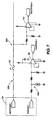
- the exemplary pump includes a pump housing 32, a diffuser 34, a flow straightener 36, and a brushless DC motor 38, which includes a stator 40 and a rotor 42.
- the housing 32 includes a flow tube 44 having a blood flow path 46 therethrough, a blood inlet 48, and a blood outlet 50.
- the stator 40 is attached to the pump housing 32, is preferably located outside the flow tube 44, and has a stator field winding 52 for producing a stator magnetic field.
- the stator 40 includes three stator windings and may be three phase "Y" or "Delta” wound.
- the flow straightener 36 is located within the flow tube 44, and includes a flow straightener hub 54 and at least one flow straightener blade 56 attached to the flow straightener hub 54.
- the rotor 42 is located within the flow tube 44 for rotation in response to the stator magnetic field, and includes an inducer 58 and an impeller 60. Excitation current is applied to the stator windings 52 to generate a rotating magnetic field.
- a plurality of magnets 62 are coupled to the rotor 42. The magnets 62, and thus the rotor 42, follow the rotary field to produce rotary motion.
- the inducer 58 is located downstream of the flow straightener 36, and includes an inducer hub 64 and at least one inducer blade 66 attached to the inducer hub 64.
- the impeller 60 is located downstream of the inducer 58, and includes an impeller hub 68 and at least one impeller blade 70 attached to the impeller hub 68.
- the diffuser 34 is located within the flow tube 44 downstream of the impeller 60, and includes a diffuser hub 72 and at least one diffuser blade 74 attached to the diffuser hub 72.
- the exemplary pump further includes a front bearing assembly 76 attached to the flow straightener hub 36.
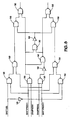
- the controller module 16 of the present invention is illustrated in greater detail in Fig. 3 in block diagram form.
- the controller module 16 is packaged in an ergonomic case 78 as illustrated in Fig. 4 .
- the controller module 16 includes a processor, such as a microcontroller 80, which in one embodiment of the invention is a model PIC16C77 microcontroller manufactured by Microchip Technology.
- the microcontroller 80 is coupled to a communications device 81 such as an RS-232 driver/receiver as is known in the art, and a hardware clock and calendar device 82, which contains clock and date information, allowing the controller module 16 to provide real-time clock and calendar information.
- the microcontroller 80 communicates with the hardware clock 82 via the I 2 C protocol.
- the microcontroller 80 also is programmed with a selftest routine, which is executed upon application of power to check components of the controller module 16.
- the controller module 16 includes first and second connectors 24, 26 for coupling the controller module 16 to a power source, such as a battery 28, or the CDAS 18 or PHSS 20.
- the connectors 24, 26 include a break-away feature, such that the connectors 24, 26 disengage themselves if a given force is applied. For example, if a battery pack connected to the controller module 16 falls on the floor, the connector will disengage rather than pull the controller module and in turn, tug on the percutaneous cable.
- the controller module 16 and the batteries 28 are contained in a support device comprising a vest 210 worn by the patient, illustrated in Fig. 5 .
- the vest 210 includes a first pocket 212 for holding the controller module 16 and two battery pouches 214 for holding two batteries 28.
- the battery pouches 214 may include integral connectors 216 adapted to receive and connect the batteries 28 to cables 218 which are coupled to the controller module connectors 24, 26.
- the cables 218 may be internal to the vest 210, accessible through openings secured by a fastener, such as a Velcro fastener (not shown).
- the battery pouches 214 also include covers 220 to further protect the batteries 28 held within the battery pouches 214.
- a particular embodiment includes a PHSS connector on one of the battery pouches 214, to which a cable connects to couple the controller module 16 to the PHSS 20.
- the controller module 16 and the batteries 28 are adapted to be connected to a belt worn by the patient, and in still further embodiments, the belt may include suspenders attached thereto to provide support for the belt.
- a motor controller 84 is coupled to the microcontroller 80, and the motor controller 84 is coupled to the pump 12.
- the operation of the brushless DC motor 38 of the present invention requires that current be applied in a proper sequence to the stator windings 52. Two stator windings 52 have current applied to them at any one time, and by sequencing the current on and off to the respective stator windings 52, a rotating magnetic field is produced.
- the motor controller 84 senses back electro motive force (EMF) voltage from the motor windings 52 to determine the proper commutation phase sequence using phase lock loop (PLL) techniques.
- EMF electro motive force
- a conductor such as a stator winding 52
- a voltage is induced.
- the voltage will increase with rotor speed 42. It is possible to sense this voltage in one of the three stator windings 52 because only two of the motor's windings 52 are activated at any one time, to determine the rotor 42 position.
- An alternative method of detecting the rotor 42 position relative to the stator 40 for providing the proper stator winding 52 excitation current sequence is to use a position sensor, such as a Hall effect sensor (not shown).
- a position sensor such as a Hall effect sensor (not shown).
- adding additional components, such as Hall effect sensors requires additional space, which is limited in any implanted device application.
- using a position detection device adds sources of system failures.
- the embodiment illustrated in Fig. 3 further includes a pump motor speed control circuit 88 coupled to the microcontroller 80 to receive inputs regarding pump operation parameters.
- the speed control circuit 88 is coupled to the motor controller 84 through a switching device 90, which couples either the speed control circuit 88 or a hardware-implemented "safe mode" speed setting 92, which is independent of the microcontroller 80.
- the switching device 90 is actuated by a microprocessor failure detector 94, which may comprise an external "watchdog" timer (not shown in Fig. 3 ) such as a monostable multivibrator, which continuously monitors the microcontroller 80. Any watchdog timers internal to the microcontroller 80 are disabled. Alternatively, the switching device 90 may be actuated by a safety plug 96 which is adapted to plug into either of the controller module connectors 24, 26. The external watchdog timer is periodically reset by the microcontroller 80 during normal controller module 16 operation. In the event that the microcontroller 80 fails, the watchdog timer will not be reset.
- a microprocessor failure detector 94 may comprise an external "watchdog" timer (not shown in Fig. 3 ) such as a monostable multivibrator, which continuously monitors the microcontroller 80. Any watchdog timers internal to the microcontroller 80 are disabled. Alternatively, the switching device 90 may be actuated by a safety plug 96 which is adapted to plug into
- the watchdog timer Upon the watchdog timer expiration, the watchdog timer activates the switching device 90, bypassing the microcontroller 80 and setting the pump 12 to a predetermined speed setting 92. This insures that the pump 12 continues to operate.
- the watchdog timer upon sensing a failure, triggers an emergency clamp and shuts down the pump 12. The emergency clamp prevents backward flow through the pump 12.
- Fig. 6 illustrates a schematic diagram of a motor control circuit 200 in accordance with an exemplary embodiment of the invention.
- the motor speed control circuit 200 includes the motor controller 84, the speed control circuit 88, the fail detector 94, the switching device 90 and the hard code speed 92 from Fig. 3 .
- the failure detector 94 includes a watchdog timer 210 coupled to the switching device 90.
- Suitable watchdog timers and switching devices include, for example, a model MAX705 monostable multivibrator and a model MAX4514 single pole-single throw CMOS analog switch, respectively, both available from Maxim Integrated Products.
- the output of the watchdog timer 210 is logically high during normal system operation (the microcontroller 80 functioning properly), and logically low when a malfunction or failure of the microcontroller 80 is detected.
- the microcontroller 80 periodically provides a watchdog timer reset signal to the input of the watchdog timer 210, which resets the watchdog timer 210, and forces its output 211 logically high.
- the output 211 of the watchdog timer is coupled to the control input 91 of the switching device 90.
- the switching device 90 is configured as a normally open switch. Therefore, the logically high signal at the control input 91 maintains the switching device 90 in a closed state, allowing the microcontroller 80 to control the pump 12 in accordance with user input.
- the watchdog timer 210 does not receive its periodic watchdog timer reset signal, after a predetermined time period (for example, one second), it will time-out and its output 211 will toggle from a logically high state to a logically low state.
- the logically low state at the control input 91 of the switching device 90 will decouple the microcontroller 80 from the motor controller 84 by opening the switching device 90.
- the switching device 90 may be operated by the safety plug 96 to manually decouple the microcontroller 80 from the motor controller 84.
- the onboard voltage reference V ref output varies from 6.5 volts to 7.5 volts (6.9 volts nominal).
- the actual pump motor speed may vary as much as ⁇ 20%.
- the speed control circuit 88 shown in Fig. 6 provides a speed control voltage input V spd level that is programmed to some proportion of the onboard voltage reference V ref value, rather than an absolute voltage level. This removes the motor speed control's dependency on the onboard voltage reference V ref output. In a particular embodiment of the invention, this reduces the pump motor speed error from ⁇ 20% to approximately ⁇ 1%.
- the speed control 88 includes a digitally programmable electronic potentiometer 212 that receives inputs from the microcontroller 80.
- a model X9312T nonvolatile digital potentiometer available from Xicor, Inc. is a suitable digital potentiometer.
- the "high" terminal 214 of the potentiometer 212 is directly coupled to the onboard voltage reference V ref output of the motor controller 84, and the "low" terminal 216 is coupled to the onboard voltage reference V ref through a voltage divider comprising resistors 218, 220.
- the resistors 218, 220 comprise 1.02k ⁇ and 1.5k ⁇ resistors, respectively.
- the potentiometer 212 thus provides a voltage output V set at its "wiper" terminal that varies from about 0.6 x V ref to V ref . Allowing the speed control voltage input V spd to equal the potentiometer 212 output voltage V set yields a pump motor speed range of about 7,500 RPM to 12,500 RPM.
- the potentiometer 212 output voltage V set is coupled to an input of a first unity gain buffer amplifier 222, the output of which is coupled, during normal operations, through the switching device 90 to an input of a second unity gain buffer amplifier 224.
- the output of the second unity gain buffer amplifier 224 is connected to the V spd input of the motor controller 84 via a resistive divider comprising resistors 226, 228.
- resistors 226, 228 should be selected so as to achieve two desired ends: 1.) minimize the loading of the V set signal when the microcontroller 80 is operating normally, and the switching device 80 is therefore closed; and 2.) provide the proper V spd voltage to realize the desired "safe mode” pump motor speed when the switching device 90 is opened via the watchdog timer 210 or the safety plug 96.
- the predetermined "safe mode" speed setting is 8,500 RPM.
- the resistors 226, 228 comprise 31.6k ⁇ and 66.5k ⁇ resistors, respectively, to achieve a V set value equal to 0.68xV ref when the switching device 90 is open.
- the microcontroller 80 may further be programmed with a pump restart feature for restarting the pump 12 in the event of a pump failure.
- the pump restart leaves the motor speed preset to its latest value.
- the microcontroller 80 initiates a start-up sequence of the motor controller 84, and locks a predetermined time period of pump performance data into the controller module's memory.
- the controller module memory is discussed further below. If the pump 12 successfully restarts in response to the pump restart feature within a given time limit (10 seconds in one embodiment), a diagnostic alarm is enabled and the motor controller 84 returns the pump 12 to the latest preset speed. If the pump 12 fails to restart, an emergency alarm is enabled and the restart sequence repeats.
- the microcontroller 80 may be programmed to limit the number of restart attempts. In a particular embodiment, the controller module 16 limits the number of restart attempts to three for a given pump stoppage.
- the microcontroller 80 includes a multiple channel analog to digital (A/D) converter, which receives indications of motor parameters from the motor controller 84.
- the controller module 16 may monitor parameters such as instantaneous motor current, the AC component of the motor current, and motor speed.
- the controller module 16 incorporates low pass digital filtering algorithms to calculate the mean values of parameters such as motor current to an accuracy of ⁇ 1% of full scale.
- the controller module 16 may include a ventricle collapse feature which detects excessive pump suction using the AC component of the motor current parameter, wherein the microcontroller 80 is programmed to detect an excessive suction condition and in response thereto, reduce the pump rate until the condition is eliminated, or until the minimum pump speed is reached.
- the excessive pump suction detection feature discriminates between a normal motor current wave form (quasi-sinusoidal after filtering) and a suspect wave form (predictably distorted). Alternately, variations in motor speed may be used to detect excess suction. Excessive pump suction parameters may be stored in an electrically erasable programmable read only memory (EEPROM) 98 coupled to the microcontroller 80.
- EEPROM electrically erasable programmable read only memory
- the controller module 16 receives power from the battery 28, the CDAS 18 or the PHSS 20 (see Fig. 1 ).
- the controller module 16 includes first and second connectors 24, 26, both of which are capable of coupling the battery 28 (which may be rechargeable), the CDAS 18 or the PHSS 20 to the controller module 16.
- the batteries 28 comprise Duracell DR36 Powersmart Batteries, which include an indicator that provides the battery's relative and absolute charge levels, and an internal memory that stores battery data, including the number of charge and discharge cycles, the battery time remaining, etc.
- the controller module 16 microcontroller 80 is programmed to query the battery 28 to obtain data related to the battery.
- the microprocessor may be programmed to display an alarm message when a battery reaches a minimum charge or time level, or if a battery has not had a desired number of charge and discharge cycles.
- the first and second connectors 24, 26 have first and second battery detect circuits 100, 102, respectively, coupled thereto.
- the battery detect circuits 100, 102 sense whether a battery 28, the CDAS 18 or PHSS 20, or nothing is coupled to the connector 24, 26.
- the battery detect circuits 100, 102 are coupled to a power source control circuit 104. If either the CDAS 18 or PHSS 20 is coupled the connectors 24, 26, the power source control circuit 104 detects this and switches the system such that the CDAS 18 or PHSS 20, as applicable, provides power to the controller module 16. If the batteries 28 are coupled to both connectors 24, 26, the battery 28 having the lower charge level (above a minimum level) is selected.
- FIG. 7 An embodiment of a battery detect circuit 100, 102 is illustrated in Fig. 7 , which includes a battery detect portion 106 and a DAS detect portion 108.
- the DAS detect portion 108 detects whether the CDAS 18 or PHSS 20 is coupled to the connector.
- the DAS detect portion 108 receives a first DAS connect input signal (DASCON1) from the first system connector 24.
- DASCON1 signal input is provided to a first comparator 110, which outputs a signal (DASPRES 1) indicating whether the CDAS 18 or PHSS 20 is connected to the terminal. If the CDAS 18 or PHSS 20 is coupled to the connector 24, DASPRES1 outputs a logically high signal, and a logically low signal is output if no device is coupled to the connector 24.
- DASPRES1 If the CDAS 18 or PHSS 20 is coupled to the connector 24, DASPRES1 outputs a logically high signal, and a logically low signal is output if no device is coupled to the connector
- a first battery connect input signal (BATTCON1) is coupled through a fuse 112 to an input of a second comparator 114, which outputs a signal (BATTPRES1) that is logically high if a battery 28 is coupled to the connector and above a predetermined minimum charge level.
- the BATTPRES1 signal is logically low if there is no battery 28 present, or if the battery 28 is below the minimum charge level.
- the first and second comparators 110, 114 may comprise two comparators of an LTC1443 quad comparator available from Linear Technology Corp. The remaining two comparators may be used for the second battery detect circuit 102.
- the exemplary logic circuit 104 comprises a plurality of two-input NAND gates 116 and a plurality of inverters 118.
- the exemplary logic circuit 104 comprises a plurality of two-input NAND gates 116 and a plurality of inverters 118.
- three 74HC00 quad NAND chips supply the NAND gates 116, and a 74HC04 inverter chip supplies the inverters 118.
- Inputs to the logic circuit 104 include the DASPRES1 and BATTPRES 1 signals from the first battery detect circuit 100, DASPRES2 and BATTPRES2 signals from the second battery detect circuit 102, and a battery select signal (BATTSEL).
- the power source control circuit 104 is implemented in software using a programmable logic device.
- the BATTSEL signal is provided by the microcontroller 80. If each of the connectors 24, 26 has a battery 28 attached, the microcontroller 80 monitors the connected batteries 28 and selects the battery 28 with the lower charge, as read from the battery pack, if the charge level is above a desired, predetermined level. The microcontroller 80 communicates with the batteries 28 via the I 2 C protocol. The microcontroller 80 queries the batteries 28 periodically to determine charge status. In an embodiment of the invention, the batteries 28 are queried upon connection and at intervals of approximately one minute thereafter. If the lower charged battery 28 falls below the minimum level, the power source control 104 switches to the higher charged battery 28.
- the microcontroller 80 If the battery 28 coupled to the first connector 24 is to be selected, the microcontroller 80 outputs a BATTSEL signal that is logically high, and if the battery 28 coupled to the second connector 26 is to be selected, BATTSEL is logically low. Moreover, if the microcontroller 80 determines that one or both batteries 28 fall below a given charge level, the microcontroller 80 may be programmed to shut down selected components of the system 10, such as the flow meter 124, to conserve power.
- the power source control circuit 104 provides two output signals, SELECT 1 and SELECT2, which in response to the DASPRES1, BATTPRES1, DASPRES2, BATTPRES2 and BATTSEL input signals, indicate whether the controller module 16 is to be powered by the device coupled to the respective connector 24, 26. If the device coupled to the first connector 24 is selected to power the controller module 16, the SELECT1 signal is logically high and the SELECT2 signal is logically low. Conversely, the SELECT1 signal is logically low and the SELECT2 signal is logically high if power is to be provided via the second connector 26.
- the power source control 104 includes two switching devices (not shown) coupled to the SELECT1 and SELECT2 output terminals and responsive thereto for connecting the controller module 16 to either the first or second connector 24,26.
- an internal battery 120 provides limited back-up power in the event of a complete power loss.
- the internal battery 120 powers the microcontroller 80 and alarms if power from the external batteries 28 is lost, and the internal battery 120 also powers the clock/calendar 82 and the system prompts 98 if the external batteries 28 are disconnected. Thus, power remains available to critical functions and to activate an alarm signaling the loss of power.
- a series of memory devices 122 are additionally coupled to the microcontroller 80 to save system parameters in the event of an emergency, such as a pump shutdown.
- the memory devices comprise three 128K banks of SRAM, which store pump parameters such as pump voltage, current, RPM and flow.
- the first of the three SRAM banks, segment 0, is the "looping bank," which employs a continuous, circular buffer that continuously stores the current performance data.
- the microcontroller 80 Upon a predetermined event, such as a pump shutdown and restart, the microcontroller 80 is programmed to transfer the data from the circular buffer to one of the other memory banks.
- the second SRAM bank, segment 1 contains the pump performance data prior to the first alarm or restart that occurs after initial power-on or a clearing of segment 0 by the CDAS (CDAS communications with the controller module will be further discussed below).
- the third bank, segment 2 contains pump performance data prior to the most recent restart event. After each restart event (or any alarm if segment 0 is clear) the data in the active looping bank are transferred to segment 0 or segment 1, as appropriate. For example, following initial start-up, if the pump stops, the processor transfers the data from the memory segment 0, the circular buffer, to memory segment 1. Assume that the pump then restarts. The pump performance data in the circular buffer associated with any subsequent predetermined events are transferred from memory segment 0 to segment 2, such that segment 2 always has the data associated with the most recent pump event.
- memory segments 0 and 1 each store 55 seconds of pump performance data segments, including pump speed (RPM), voltage, flow rate, instantaneous motor current and time. Further, sample rates for these parameters may be as follows: instantaneous motor current, 2000 samples per second; flow rate, 333 samples per second; pump speed, 10 samples per second; and voltage, 10 samples per second. The sampling resolution for these parameters is eight bits in one embodiment of the invention.
- Each memory segment includes predetermined boundaries for each sampled parameter. For example, pump motor current requires 110,000 bytes to store 55 seconds at 2000 samples per second which may be stored in a predetermined memory array. Defining parameter boundaries in this fashion allows a technician to request parametric data by reading a range of blocks.
- the last block in each memory segment contains time stamp information available from the real-time clock and calendar along with a start and stop memory pointer for each parameter.
- FIG. 3 Another novel aspect of an embodiment to be used with the inventive controller is the inclusion of an integral flow meter 124, as shown in Fig. 3 .
- an integral flow meter 124 As disclosed above, at least one flow sensor 14 is implanted down stream of the pump 12. Alternately, a flow sensor 14 may be integrated with the pump 12.
- a Custom 12A dual channel flow sensor available from Transonic Systems, Inc. is implanted downstream of the pump 12 in an embodiment of the invention.
- the flow meter 124 which may comprise a Transonic Systems, Inc. model FPT110 dual channel flow meter, is coupled between the implanted flow sensor 14 and the microcontroller 80.
- the flow meter 124 averages the data from the two flow sensor channels and outputs flow rate data to the microprocessor A/D converter (not shown), allowing the microprocessor to monitor instantaneous flow rate.
- the flow signal amplitude of each flow meter channel is also provided to the microprocessor to monitor system integrity.
- flow rate a true measure of system performance (flow rate) is available for analysis, in addition to pump parameters such as pump speed. Further, since the flow meter 124 is an integral component of the controller module 16, flow rate may be displayed on the controller module display (described below), and flow rate data may be saved in the controller module memory 122 for later analysis.
- Providing a flow meter 124 as an integral component of the portable controller module 16 solves a significant shortcoming of prior art VAD and artificial heart systems, which typically do not capture and display flow rate data on a portable device. Even if a known VAD or artificial heart system were to include an implanted flow transducer, prior art systems would require an external console to display and capture the flow data. This valuable system information would be lost whenever the system is not coupled to the external console. On the other hand, means to display and analyze flow rate data for all pump operating time may be provided, whether or not the controller module is connected to the CDAS.
- the EEPROM 98 connected to the microcontroller 80 in addition to storing excessive suction detection parameters, stores prompts and messages for display and manipulation via a user interface 126 (not shown in Fig. 3 ).
- the microprocessor communicates with the EEPROM 98 via the I 2 C protocol in one embodiment.
- the user interface 126 may comprise a display 128 and an input device 130.
- the controller module display 128 comprises a two-row, back-lit 16-character LCD display; two multicolored LEDs 132 which indicate battery status; and an additional LED 134 which indicates when the unit is in the safemode.
- the input device 130 may include a keypad, which in an embodiment of the invention, includes two sealed keypad switches to perform the functions of alarm silence and display scroll.
- the display 128 may be configured to display messages in multiple languages.
- the message displays may be arranged such that predetermined display character positions are reserved for displaying the parameter or alarm "label,” such as "PUMP SPEED.” These labels may be stored in one or more languages in the message and parameter EEPROM 98. Other predetermined positions on the display 128 may be reserved for displaying the parameter value reading as received by the controller module.
- the default LCD message displayed is flow rate and power on the first display line and the percent of capacity or time remaining for each battery connected on the second display line. Alternately, if the flow meter 124 is disabled, motor speed and motor power may be displayed on the first display line. If the controller module is coupled to the CDAS, the LCD displays "DAS CONNECTED.” Other main LCD messages displayed include “PERFORMING SELF TEST,” and “VAD SYSTEM MODEL NUMBER,” which are toggled upon initial power-up while the microprocessor executes the self test sequence.
- the controller module 16 is also capable of displaying diagnostic messages on the LCD 128.
- a user may scroll the diagnostic messages by pressing the display scroll keypad switch 130.
- the first depression of the display scroll key initially illuminates the backlight (if not previously lit), and all subsequent scroll key depressions continuously scan through the message displays.
- Diagnostic messages included in a particular embodiment of the invention include the date, time and unit serial number; motor current; motor speed; received amplitudes of the flow sensor channels; excess suction enabled (or disabled); flow sensor enabled (or disabled) and physiological control enabled (disabled).
- the controller module 16 also provides audible alarms and alarm messages, which are displayed on the LCD.
- The.audible alarm may use different distinct sounds to indicate diagnostic and emergency events.
- the diagnostic alarm may have multiple volume levels and may repeat a series of beeping tones which increase in rate and volume until answered by pressing the alarm silence key. Pressing the alarm silence key silences the audible alarm, but does not clear the alarm message displayed on the LCD 128.
- diagnostic alarms are provided when a measured parameter (PARAMETER) differs from a predetermined parameter value (PARAMETER alarm ) by a threshold amount.
- the PARAMETER alarm and threshold values are stored in the EEPROM.
- the EEPROM provides non-volatile storage for these important messages and system parameters.
- the emergency audible alarm may comprise a continuous beep at maximum volume level to indicate the severity of the event. If both diagnostic and emergency events occur simultaneously, the microprocessor is programmed to sound only the emergency alarm.
- the multicolored battery status LEDs 132 may indicate various battery conditions. For example, a solid green indicates that the battery is in use and blinking amber indicates a low charge level, expired battery, or battery disconnected. If the battery status LED is off, the charged battery is connected but not presently in use, and alternating amber and green indicates the self test mode.
- the safe mode indicator 134 is activated by the watchdog timer 94 in the event of a microcontroller 80 failure. Emergency alarms and diagnostic alarms for an embodiment of the invention are displayed in Table 1 and Table 2 below.
- the CDAS 18 includes a computer 128, which includes a processor 140, at least one memory storage device 142, a video display 144 and an input device 146, such as a computer keyboard.
- the video display 144 is an LCD.
- the CDAS 18 is mounted on a moveable cart 148 such that the CDAS 18 can escort a patient during movements within the hospital.
- the CDAS 18 is configured for use within a hospital setting, and is not intended to go home with a patient having an implanted pump 12.
- the CDAS 18 further collects and displays data from the controller module 16, sends comments and data to the controller module 16, and supplies power to the controller module 16.
- the primary power source for the CDAS 18 is 120 volt, 60 Hz AC power, or 220 volt, 50 Hz AC power as from standard wall electrical outlets.
- the CDAS 18 includes a medical grade power supply 149 such as is known in the art for providing power to the controller module 16.
- the AC mains are isolated by a medical grade isolation transformer 150.
- the CDAS 18 further includes a battery backed uninterruptable power supply (UPS) system 152.
- the UPS 152 is capable of operating the controller module 16 alone for eight hours and the controller module 16 and CDAS 18 for one hour when AC power is unavailable.
- the CDAS 18 provides an operator interface to the controller module in addition to the LCD 128 and controller module keypad 130.
- the CDAS 18 includes a communications port 153, such as a standard RS-232 communications port and an A/D converter 154. All data communication between the CDAS 18 and the controller module 16 is electrically isolated.
- a cable 155 couples the CDAS 18 to one of the controller module connectors 24, 26, through which the CDAS 18 provides power and communicates with the controller module 16.
- the cable 155 connects the CDAS power supply 149 to the battery detect circuit 100,102 associated with the appropriate controller module connector 24, 26.
- the same cable 155 additionally couples the communications port 153 to the RS-232 driver/receiver 81 and the digital to analog converter 154 to the flow meter 124 and the motor controller 84.
- the CDAS 18 is able to exchange commands and other information with the controller module 16, such as digital data stored in the parameters and messages EEPROM 98 or the controller module memory devices 122. Further, the CDAS 18 is directly coupled to the motor controller 84 and the flow meter 124 to receive real-time analog motor current and flow data, respectively. The real-time analog data received may be isolated and filtered, then displayed in real time on the CDAS video display 144.
- digital data regarding pump voltage, current, RPM and flow data are stored in the controller module memory device 128 and are downloaded to the CDAS 18 via the RS-232 interface.
- the CDAS 18 may then plot this information on the video display 144, and store the data in the CDAS memory device 142. Further, diagnostic and emergency messages may be downloaded and a log kept of these messages.
- the CDAS 18 is also coupled to the controller module real-time clock and calendar 82 so that these parameters may be synchronized with the controller module 18.
- the CDAS 18 may further be coupled to other devices external to the controller module 16. Examples of such devices may include an ex-vivo blood pressure transducer for capturing and displaying blood pressure information during surgery.
- An auxiliary contact microphone 158 may be coupled to the CDAS 18 to capture and display acoustic information for monitoring pump 12 condition.
- data in addition to that provided by the controller module 16 may be captured, stored, and displayed by the CDAS 18.
- the CDAS 18 further provides an interface for an operator to change system parameters such as pump speed, alarm thresholds and excess suction parameters, and to run test routines on the system.
- system access is password controlled based on different user levels. For example, Level 1 users (patient) may be allowed to view alarm messages and pump operating parameters; Level 2 users (physician) may view alarm messages and pump operating parameters, and also make minor system changes such as adjusting pump speed; and Level 3 users (technician) have access to all CDAS functionality.
- Another function related to the CDAS 18/controller module 16 interface involves diagnosing pump 12 problems.
- pump parameters are stored for a predetermined time period prior to two emergency events in the controller module memory. If, for example, the pump 12 fails while the controller module 16 is not connected to the CDAS 18, 55 seconds of pump performance data is stored in the controller module memory 122.
- analysis of the pump parameters just prior to the failure may be essential for diagnosing the problem.
- Examples of additional controller module 16 operations performed via the CDAS 18 in an embodiment of the invention include programming and verifying multilingual controller module LCD messages, real-time clock/calendar, parameters for use by the excess suction feature, alarm parameters, and operational parameters. Further, a user may operate the pump motor, the excess suction feature, and the flow meter via the CDAS, or closed loop physiological system control may be activated.
- the controller module includes processing, memory, and operator interface capabilities.
- the system 10 may be operated for an extended period independent of the CDAS 18 in a truly portable mode.
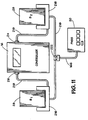
- the PHSS 20 of an embodiment of the invention is illustrated in Fig. 10 .
- the PHSS 20 is a portable device that can be hand-carried, as opposed to being moved on a cart as the consoles of prior art VAD systems.
- the PHSS 20 comprises a power supply 160 sourced by 120 volt, 60 Hz AC power or 220 volt, 50 Hz AC power as from standard wall electrical outlets.
- the AC mains are isolated by a medical grade isolation transformer 162.
- the PHSS further includes at least one compartment 164 having a connector (not shown) for receiving one or more batteries 28.
- the PHSS includes four battery compartments 164, each of the compartments 164 being coupled to an integral battery charger 30.
- the PHSS 20 is coupled to the controller module 16 via a cable 166.
- Fig. 11 illustrates the PHSS 20 connection to the controller module for one embodiment of the invention.
- the PHSS cable 166 is coupled to the PHSS connector 222, which may be connected directly to one of the battery connectors 216 or connected to a cable 218 between the battery connectors 216.
- the battery connectors 216 are coupled to the controller module connectors 24, 26.
- the DASPRES 1 or DASPRES2 signal of the power control circuit 104 will be logically high. Therefore, the power control circuit 104 will power the controller module 16 from the PHSS power supply.
- the controller module 16 will then attempt to communicate via the RS-232 interface with the connected device. Since the PHSS 20 does not include communications capabilities, the controller module 16 then knows that the PHSS 20 is connected rather than the CDAS 18.
- the PHSS connector 222 further includes a logic device or circuit (not shown) for further managing the system power when the PHSS 20 is coupled to the controller module 16.
- a logic device or circuit (not shown) for further managing the system power when the PHSS 20 is coupled to the controller module 16.
- the controller module 16 is powered via the PHSS.
- the batteries 28 may be removed from the battery connectors 216. A message noting that it is safe to remove the batteries may be displayed on the LCD 128.
- the batteries 28 are then placed in the battery compartments 164, where they either provide a back-up to the PHSS 20, or they are recharged by the charger 30 contained within the PHSS 20.
- Using the batteries 28 as a power back-up eliminates the need for an additional back-up power supply, in turn reducing the size requirement and making the PHSS more economical.
- the PHSS connector 222 queries the batteries 28 held in the compartments 164 to determine their respective charge levels. In one embodiment, the battery with the highest charge provides a power back-up to the PHSS. The remaining battery is recharged. If the recharging battery's charge level reaches a point higher than the back-up battery 28, PHSS connector 222 reverses the battery 28 function so the back-up battery 28 may now recharge.
- the remaining battery compartments 64 may hold additional spare batteries, which are either recharged or provide back-up to the PHSS power supply as determined by the logic circuit within the PHSS connector 222.
- the PHSS further includes an additional compartment 172 for holding a spare controller module (not shown), and a storage space 170 for holding spare cables and the like.
Claims (9)
- Unité de contrôle (16) pour système de pompage implantable comprenant une pompe (12) ayant un moteur électrique (38), l'unité de contrôle (16) comprenant :un processeur (80),un dispositif de commande de moteur (84) couplé électriquement au processeur (80), le dispositif de commande de moteur (84) étant connectable à un moteur de système de pompage implantable et utilisable pour assurer l'alimentation électrique d'un moteur de pompage (38) connecté à celui-ci de manière à ce que le moteur de pompage (38) fonctionne à un débit souhaité, le dispositif de commande de moteur (84) étant adapté pour recevoir des informations de paramètres de fonctionnement du moteur de pompage (38) connecté à celui-ci et pour délivrer des représentations numériques des paramètres de fonctionnement du moteur de pompage au processeur (80),un premier dispositif de mémoire (122) couplé au processeur (80) pour stocker les données numériques représentant les paramètres de fonctionnement du système, etune interface utilisateur (126) couplée au processeur (80) pour afficher les paramètres de fonctionnement du moteur de pompage,dans laquelle le premier dispositif de mémoire (122) comprend une pluralité de rangées de mémoire (SRAM0, SRAM1, SRAM2), dans laquelle le processeur (80) est programmé de manière à ce qu'au moins l'une des rangées de mémoire fonctionne en tant que mémoire tampon circulaire pour stocker continuellement les paramètres de moteur de pompage en temps réel par incréments de temps prédéfinis et la pluralité de rangées de mémoire (SRAM00, SRAM1, SRAM2) comprend au moins une première rangée de mémoire et une deuxième rangée de mémoire (SRAM0, SRAM1), dans laquelle le processeur (80) est programmé pour faire fonctionner la mémoire tampon circulaire dans la mémoire sur la première rangée de mémoire (SRAM0), et dans laquelle le processeur (80) est programmé pour transférer les données de la première rangée de mémoire (SRAM0) à la deuxième rangée de mémoire (SRAM1) lors d'un premier événement prédéterminé, caractérisée en ce que la pluralité de mémoires (SRAM0, SRAM1, SRAM2) comprend en outre une troisième rangée de mémoire (SRAM2), dans laquelle le processeur (80) est programmé pour transférer les données de la première rangée de mémoire (SRAM0) à la troisième rangée de mémoire (SRAM2) lors de tout événement prédéterminé à la suite du premier événement prédéterminé.
- Unité de contrôle selon la revendication 1, caractérisée en ce qu'elle comprend en outre une source d'alimentation électrique (28) connectée au processeur (80).
- Unité de contrôle selon la revendication 1, caractérisée en ce qu'elle comprend en outre au moins un connecteur (24) pour coupler l'unité de contrôle (16) à une source d'alimentation électrique externe (28).
- Unité de contrôle selon la revendication 1, caractérisée en ce qu'elle comprend en outre une horloge matérielle et un dispositif de calendrier (82) couplés au processeur (80).
- Unité de contrôle selon la revendication 1, caractérisée en ce que le premier dispositif de mémoire (122) comprend une SRAM.
- Unité de contrôle selon la revendication 1, caractérisée en ce qu'elle comprend en outre un dispositif de détection de défaillance (94) adapté pour détecter une défaillance de processeur, le dispositif de détection de défaillance (94) étant utilisable pour découpler le processeur (80) du dispositif de commande de moteur (84) en réponse à la défaillance de processeur détectée.
- Unité de contrôle selon la revendication 1, caractérisée en ce que l'interface utilisateur comprend un affichage de texte (128), et en ce que le processeur (80) est programmé pour afficher sélectivement les données stockées dans le premier dispositif de mémoire (122).
- Unité de contrôle selon la revendication 7, caractérisée en ce qu'elle comprend en outre un deuxième dispositif de mémoire (98) couplé au processeur (80) comprenant des données numériques stockées dans celui-ci, et en ce que le processeur (80) est programmé pour afficher sélectivement les données sur l'affichage de texte.
- Unité de contrôle selon la revendication 1, caractérisée en ce que :l'unité de commande de moteur (84) comprend une borne de sortie de tension de référence (V REF ) etune borne d'entrée de tension de contrôle de débit (VSPD ), etl'unité de commande de moteur (84) comprend en outre un dispositif de contrôle de débit de pompage (88) adapté pour calculer et fournir un niveau de tension à la borne d'entrée de tension de contrôle de débit (V SPD ) en proportion de la tension de référence pour atteindre un débit de pompage souhaité.
Priority Applications (1)
| Application Number | Priority Date | Filing Date | Title |
|---|---|---|---|
| DE69836495.3T DE69836495T3 (de) | 1997-10-02 | 1998-10-02 | Steuermodul für implantierbares Pumpsystem |
Applications Claiming Priority (3)
| Application Number | Priority Date | Filing Date | Title |
|---|---|---|---|
| US6066597P | 1997-10-02 | 1997-10-02 | |
| US60665P | 1997-10-02 | ||
| PCT/US1998/021015 WO1999017819A1 (fr) | 1997-10-02 | 1998-10-02 | Systeme de pompage implantable |
Publications (3)
| Publication Number | Publication Date |
|---|---|
| EP1019117A1 EP1019117A1 (fr) | 2000-07-19 |
| EP1019117B1 EP1019117B1 (fr) | 2006-11-22 |
| EP1019117B2 true EP1019117B2 (fr) | 2015-03-18 |
Family
ID=22031003
Family Applications (1)
| Application Number | Title | Priority Date | Filing Date |
|---|---|---|---|
| EP98952096.0A Expired - Lifetime EP1019117B2 (fr) | 1997-10-02 | 1998-10-02 | Unité de contrôle pour système de pompage implantable |
Country Status (7)
| Country | Link |
|---|---|
| US (3) | US6183412B1 (fr) |
| EP (1) | EP1019117B2 (fr) |
| AT (1) | ATE345825T1 (fr) |
| AU (1) | AU9787498A (fr) |
| DE (1) | DE69836495T3 (fr) |
| TW (1) | TW404842B (fr) |
| WO (1) | WO1999017819A1 (fr) |
Families Citing this family (335)
| Publication number | Priority date | Publication date | Assignee | Title |
|---|---|---|---|---|
| US6783328B2 (en) * | 1996-09-30 | 2004-08-31 | Terumo Cardiovascular Systems Corporation | Method and apparatus for controlling fluid pumps |
| US6554798B1 (en) | 1998-08-18 | 2003-04-29 | Medtronic Minimed, Inc. | External infusion device with remote programming, bolus estimator and/or vibration alarm capabilities |
| ITRE990003A1 (it) * | 1999-01-19 | 2000-07-18 | Maria Addolorata Civino | Capanno per smaltatura a disco doppio o singolo . |
| US20030060765A1 (en) * | 2000-02-16 | 2003-03-27 | Arthur Campbell | Infusion device menu structure and method of using the same |
| CA2404636A1 (fr) * | 2000-03-27 | 2001-10-04 | The Cleveland Clinic Foundation | Systeme de controle chronique du rendement des pompes sanguines rotodynamiques |
| ITTO20010448A1 (it) * | 2001-05-14 | 2001-08-14 | Eva Hubertova | Dispositivo biomeccanico di supporto alla rivascolarizzazione. |
| WO2003019311A2 (fr) * | 2001-08-24 | 2003-03-06 | Bs & B Safety Systems, Inc. | Systeme de surveillance pour recipient sous pression |
| US6970741B1 (en) | 2001-09-18 | 2005-11-29 | Advanced Bionics Corporation | Monitoring, preventing, and treating rejection of transplanted organs |
| US7308303B2 (en) | 2001-11-01 | 2007-12-11 | Advanced Bionics Corporation | Thrombolysis and chronic anticoagulation therapy |
| US7396327B2 (en) * | 2002-01-07 | 2008-07-08 | Micromed Technology, Inc. | Blood pump system and method of operation |
| US8323173B2 (en) * | 2002-01-07 | 2012-12-04 | Micromed Technology, Inc. | Method and system for physiologic control of an implantable blood pump |
| WO2004002552A1 (fr) * | 2002-06-26 | 2004-01-08 | Micromed Technology, Inc. | Procede et systeme de commande physiologique d'une pompe a sang |
| CA2471484A1 (fr) | 2002-01-08 | 2003-07-17 | Micromed Technology, Inc. | Procede et systeme de detection de collapsus ventriculaire |
| WO2003068292A1 (fr) * | 2002-02-11 | 2003-08-21 | National University Of Singapore | Dispositif et procede d'assistance cardiaque physiologiquement compatible |
| US6991595B2 (en) * | 2002-04-19 | 2006-01-31 | Thoratec Corporation | Adaptive speed control for blood pump |
| EP1558303A4 (fr) * | 2002-06-14 | 2010-12-08 | Michael Vollkron | Technique et systeme de detection d'aspiration ventriculaire |
| US20040068230A1 (en) * | 2002-07-24 | 2004-04-08 | Medtronic Minimed, Inc. | System for providing blood glucose measurements to an infusion device |
| US6949066B2 (en) | 2002-08-21 | 2005-09-27 | World Heart Corporation | Rotary blood pump diagnostics and cardiac output controller |
| US7284956B2 (en) * | 2002-09-10 | 2007-10-23 | Miwatec Co., Ltd. | Methods and apparatus for controlling a continuous flow rotary blood pump |
| US6817836B2 (en) * | 2002-09-10 | 2004-11-16 | Miwatec Incorporated | Methods and apparatus for controlling a continuous flow rotary blood pump |
| US20040122353A1 (en) * | 2002-12-19 | 2004-06-24 | Medtronic Minimed, Inc. | Relay device for transferring information between a sensor system and a fluid delivery system |
| IL154531A (en) * | 2003-02-19 | 2006-04-10 | Yair Tal | Method and system for regulating blood flow |
| US6838852B1 (en) * | 2003-04-01 | 2005-01-04 | General Motors Corporation | Plug and play electric machine |
| WO2004110360A2 (fr) * | 2003-05-16 | 2004-12-23 | Acorda Therapeutics, Inc. | Mutants de degradation du proteoglycane pour le traitement du systeme nerveux central |
| EP1486217B1 (fr) * | 2003-06-12 | 2010-05-12 | Terumo Kabushiki Kaisha | Système à pompe cardiaque artificielle et apparail de commande |
| US7494459B2 (en) * | 2003-06-26 | 2009-02-24 | Biophan Technologies, Inc. | Sensor-equipped and algorithm-controlled direct mechanical ventricular assist device |
| WO2006029216A2 (fr) * | 2004-09-07 | 2006-03-16 | Micromed Cardiovascular, Inc. | Procede et systeme pour le controle physiologique de pompe a sang |
| US20090226328A1 (en) * | 2004-11-16 | 2009-09-10 | Micromed Technology, Inc. | Remote Data Monitor For Heart Pump System |
| US20060247606A1 (en) * | 2005-03-09 | 2006-11-02 | Batch Richard M | System and method for controlling access to features of a medical instrument |
| KR100846074B1 (ko) * | 2005-05-09 | 2008-07-14 | 주식회사 엘지화학 | 파우치형 전지의 입체형 전극단자 |
| EP2438937B1 (fr) | 2005-06-06 | 2015-10-28 | The Cleveland Clinic Foundation | Pompe sanguine |
| JP2008543378A (ja) * | 2005-06-08 | 2008-12-04 | マイクロメッド・テクノロジー・インコーポレイテッド | 人工心臓システム |
| US20070052389A1 (en) * | 2005-07-19 | 2007-03-08 | Michiel Kooij | Battery receptacle |
| US20070077153A1 (en) * | 2005-09-30 | 2007-04-05 | Austen Timothy F | Rechargeable AC/DC pump |
| US20090222671A1 (en) | 2005-10-25 | 2009-09-03 | Burbank Jeffrey H | Safety features for medical devices requiring assistance and supervision |
| US20070142923A1 (en) | 2005-11-04 | 2007-06-21 | Ayre Peter J | Control systems for rotary blood pumps |
| CA2631227A1 (fr) * | 2005-11-28 | 2007-05-31 | Myotech Llc | Procede et appareil d'activation ventriculaire mecanique directe avec effraction minimale |
| EP1981585B1 (fr) * | 2006-01-27 | 2019-03-06 | CircuLite, Inc. | Systeme d'assistance cardiaque |
| US20070255126A1 (en) * | 2006-04-28 | 2007-11-01 | Moberg Sheldon B | Data communication in networked fluid infusion systems |
| US20070255125A1 (en) * | 2006-04-28 | 2007-11-01 | Moberg Sheldon B | Monitor devices for networked fluid infusion systems |
| US20070254593A1 (en) * | 2006-04-28 | 2007-11-01 | Medtronic Minimed, Inc. | Wireless data communication for a medical device network that supports a plurality of data communication modes |
| US8073008B2 (en) * | 2006-04-28 | 2011-12-06 | Medtronic Minimed, Inc. | Subnetwork synchronization and variable transmit synchronization techniques for a wireless medical device network |
| US20070253380A1 (en) * | 2006-04-28 | 2007-11-01 | James Jollota | Data translation device with nonvolatile memory for a networked medical device system |
| JP4814717B2 (ja) * | 2006-07-28 | 2011-11-16 | Hoya株式会社 | 電子内視鏡、及び、電子内視鏡システム |
| US8333686B2 (en) * | 2006-08-30 | 2012-12-18 | Circulite, Inc. | Cannula insertion devices, systems, and methods including a compressible member |
| US7905823B2 (en) * | 2006-08-30 | 2011-03-15 | Circulite, Inc. | Devices, methods and systems for establishing supplemental blood flow in the circulatory system |
| JP5537939B2 (ja) | 2006-08-30 | 2014-07-02 | サーキュライト・インコーポレーテッド | 循環系に補足的な血流を確立するための装置、方法、及びシステム |
| CA2663586C (fr) * | 2006-09-14 | 2014-10-28 | Circulite, Inc | Pompe a sang intravasculaire et catheter |
| US7963905B2 (en) | 2006-10-11 | 2011-06-21 | Thoratec Corporation | Control system for a blood pump |
| AU2007221905B2 (en) * | 2006-10-11 | 2012-07-12 | Thoratec Corporation | Control System for a Blood Pump |
| US8390244B2 (en) * | 2007-03-30 | 2013-03-05 | Nipro Healthcare Systems, Llc | Rechargeable battery backup apparatus and method for insulin pump |
| CN101678160A (zh) * | 2007-04-05 | 2010-03-24 | 麦克罗美德技术公司 | 血泵系统 |
| DE102007022286B4 (de) * | 2007-05-12 | 2009-01-15 | Dräger Medical AG & Co. KG | Medizinisches System mit galvanischer Trennung |
| US20080300572A1 (en) * | 2007-06-01 | 2008-12-04 | Medtronic Minimed, Inc. | Wireless monitor for a personal medical device system |
| US9993588B2 (en) * | 2007-06-06 | 2018-06-12 | WorldHeart, Inc. | Wearable VAD controller with reserve battery |
| JP5201887B2 (ja) * | 2007-06-20 | 2013-06-05 | テルモ株式会社 | 人工心臓用血液ポンプシステムおよび機器監視システム |
| CA2693223C (fr) * | 2007-07-19 | 2015-05-19 | Circulite, Inc. | Canule destinee a etre implantee dans une chambre cardiaque, et systemesconnexes |
| US8343029B2 (en) * | 2007-10-24 | 2013-01-01 | Circulite, Inc. | Transseptal cannula, tip, delivery system, and method |
| US20090112626A1 (en) * | 2007-10-30 | 2009-04-30 | Cary Talbot | Remote wireless monitoring, processing, and communication of patient data |
| US8376926B2 (en) * | 2007-11-29 | 2013-02-19 | Micromed Technology, Inc. | Rotary blood pump |
| US7794384B2 (en) * | 2007-12-07 | 2010-09-14 | Terumo Heart, Inc. | Dual communication interface for artificial heart system |
| US8313467B2 (en) | 2007-12-27 | 2012-11-20 | Medtronic Minimed, Inc. | Reservoir pressure equalization systems and methods |
| US20090177142A1 (en) | 2008-01-09 | 2009-07-09 | Smiths Medical Md, Inc | Insulin pump with add-on modules |
| US7856335B2 (en) * | 2008-01-25 | 2010-12-21 | Micromed Technology, Inc. | Device, method, and system for calibration of a flow meter used in conjunction with a ventricular assist device |
| JP5250755B2 (ja) * | 2008-03-25 | 2013-07-31 | 株式会社サンメディカル技術研究所 | 補助人工心臓ポンプ駆動装置及び補助人工心臓システム |
| US9515538B2 (en) | 2008-05-29 | 2016-12-06 | Nidec Motor Corporation | Dynamoelectric machine assemblies having memory for use by external devices |
| US10842645B2 (en) | 2008-08-13 | 2020-11-24 | Smed-Ta/Td, Llc | Orthopaedic implant with porous structural member |
| US9616205B2 (en) | 2008-08-13 | 2017-04-11 | Smed-Ta/Td, Llc | Drug delivery implants |
| US9700431B2 (en) | 2008-08-13 | 2017-07-11 | Smed-Ta/Td, Llc | Orthopaedic implant with porous structural member |
| US20100042213A1 (en) | 2008-08-13 | 2010-02-18 | Nebosky Paul S | Drug delivery implants |
| EP2339973B1 (fr) | 2008-08-13 | 2017-10-18 | Smed-Ta/Td, Llc | Implants d'apport de médicament |
| WO2010025386A1 (fr) | 2008-08-29 | 2010-03-04 | Smed-Ta/Td, Llc | Implant orthopédique |
| AU2009296514B2 (en) | 2008-09-26 | 2014-04-10 | Carnegie Mellon University | Magnetically-levitated blood pump with optimization method enabling miniaturization |
| US8208973B2 (en) * | 2008-11-05 | 2012-06-26 | Medtronic Minimed, Inc. | System and method for variable beacon timing with wireless devices |
| EP2194278A1 (fr) | 2008-12-05 | 2010-06-09 | ECP Entwicklungsgesellschaft mbH | Pompe à fluide dotée d'un rotor |
| US20100161346A1 (en) * | 2008-12-24 | 2010-06-24 | Kristen Getschmann | Systems and Methods for Providing Bolus Dosage Recommendations |
| EP2216059A1 (fr) | 2009-02-04 | 2010-08-11 | ECP Entwicklungsgesellschaft mbH | Dispositif de cathéter doté d'un cathéter et d'un dispositif d'actionnement |
| EP2229965A1 (fr) | 2009-03-18 | 2010-09-22 | ECP Entwicklungsgesellschaft mbH | Pompe à fluide dotée d'une forme spéciale de lame de rotor |
| US8460168B2 (en) * | 2009-03-27 | 2013-06-11 | Circulite, Inc. | Transseptal cannula device, coaxial balloon delivery device, and methods of using the same |
| US20100249491A1 (en) * | 2009-03-27 | 2010-09-30 | Circulite, Inc. | Two-piece transseptal cannula, delivery system, and method of delivery |
| US8315885B2 (en) | 2009-04-14 | 2012-11-20 | Baxter International Inc. | Therapy management development platform |
| EP2246078A1 (fr) | 2009-04-29 | 2010-11-03 | ECP Entwicklungsgesellschaft mbH | Agencement d'arbres doté d'un arbre se déroulant à l'intérieur d'une enveloppe rempli de fluide |
| EP2248544A1 (fr) | 2009-05-05 | 2010-11-10 | ECP Entwicklungsgesellschaft mbH | Pompe à fluide à diamètre modifiable, notamment à des fins médicales |
| US9514279B2 (en) | 2009-05-05 | 2016-12-06 | Carefusion 303, Inc. | Model-based infusion site monitor |
| US8372145B2 (en) | 2009-05-19 | 2013-02-12 | Hisham M. F. SHERIF | Implantable artificial ventricle having low energy requirement |
| US9782527B2 (en) | 2009-05-27 | 2017-10-10 | Tc1 Llc | Monitoring of redundant conductors |
| EP2266640A1 (fr) | 2009-06-25 | 2010-12-29 | ECP Entwicklungsgesellschaft mbH | Pale comprimable et extensible pour une pompe à fluide |
| US8344847B2 (en) * | 2009-07-09 | 2013-01-01 | Medtronic Minimed, Inc. | Coordination of control commands in a medical device system having at least one therapy delivery device and at least one wireless controller device |
| US20110009724A1 (en) * | 2009-07-09 | 2011-01-13 | Medtronic Minimed, Inc. | Providing contextually relevant advertisements and e-commerce features in a personal medical device system |
| EP2282070B1 (fr) | 2009-08-06 | 2012-10-17 | ECP Entwicklungsgesellschaft mbH | Dispositif de cathéter doté d'un dispositif d'accouplement pour un dispositif d'entraînement |
| DE202009011683U1 (de) * | 2009-08-28 | 2011-01-20 | Schmidt, Antje, Dipl.-Designerin | Gürteltasche für Kunstherzsystem |
| US8487758B2 (en) | 2009-09-02 | 2013-07-16 | Medtronic Minimed, Inc. | Medical device having an intelligent alerting scheme, and related operating methods |
| EP2298371A1 (fr) | 2009-09-22 | 2011-03-23 | ECP Entwicklungsgesellschaft mbH | Elément fonctionnel, notamment pompe à fluide, doté d'un boîtier et d'un élément de transport |
| EP2298372A1 (fr) | 2009-09-22 | 2011-03-23 | ECP Entwicklungsgesellschaft mbH | Rotor pour une pompe axiale pour le transport d'un fluide |
| DK3441616T3 (da) | 2009-09-22 | 2023-05-30 | Ecp Entw Mbh | Komprimerbar rotor til en fluidpumpe |
| EP2314331B1 (fr) | 2009-10-23 | 2013-12-11 | ECP Entwicklungsgesellschaft mbH | Agencement de pompes de cathéter et agencement d'arbres flexible doté d'une âme |
| EP2314330A1 (fr) | 2009-10-23 | 2011-04-27 | ECP Entwicklungsgesellschaft mbH | Agencement d'arbres flexible |
| US8386042B2 (en) * | 2009-11-03 | 2013-02-26 | Medtronic Minimed, Inc. | Omnidirectional accelerometer device and medical device incorporating same |
| US20110112353A1 (en) * | 2009-11-09 | 2011-05-12 | Circulite, Inc. | Bifurcated outflow cannulae |
| US8574201B2 (en) | 2009-12-22 | 2013-11-05 | Medtronic Minimed, Inc. | Syringe piston with check valve seal |
| EP2338541A1 (fr) | 2009-12-23 | 2011-06-29 | ECP Entwicklungsgesellschaft mbH | Rotor radial pouvant être comprimé et extensible pour une pompe à fluide |
| EP2338539A1 (fr) | 2009-12-23 | 2011-06-29 | ECP Entwicklungsgesellschaft mbH | Dispositif de pompage doté d'un dispositif de détection |
| US8755269B2 (en) * | 2009-12-23 | 2014-06-17 | Medtronic Minimed, Inc. | Ranking and switching of wireless channels in a body area network of medical devices |
| US20110152970A1 (en) * | 2009-12-23 | 2011-06-23 | Medtronic Minimed, Inc. | Location-based ranking and switching of wireless channels in a body area network of medical devices |
| EP2338540A1 (fr) | 2009-12-23 | 2011-06-29 | ECP Entwicklungsgesellschaft mbH | Palette de transport pour un rotor pouvant être comprimé |
| US8562508B2 (en) | 2009-12-30 | 2013-10-22 | Thoratec Corporation | Mobility-enhancing blood pump system |
| EP2519274B1 (fr) * | 2009-12-30 | 2016-04-20 | Thoratec Corporation | Système de pompe à sang à amélioration de la mobilité |
| EP2347778A1 (fr) | 2010-01-25 | 2011-07-27 | ECP Entwicklungsgesellschaft mbH | Pompe à fluide dotée d'un rotor radial comprimable |
| US20110196189A1 (en) * | 2010-02-09 | 2011-08-11 | Myocardiocare, Inc. | Extra-cardiac differential ventricular actuation by inertial and baric partitioning |
| US9662431B2 (en) | 2010-02-17 | 2017-05-30 | Flow Forward Medical, Inc. | Blood pump systems and methods |
| US9555174B2 (en) | 2010-02-17 | 2017-01-31 | Flow Forward Medical, Inc. | Blood pump systems and methods |
| AU2011217974B2 (en) | 2010-02-17 | 2015-08-20 | Artio Medical, Inc. | System and method to increase the overall diameter of veins |
| CA2791906C (fr) | 2010-03-05 | 2015-01-20 | Minnetronix Inc. | Dispositif de commande portable avec source d'energie integree pour systemes mecaniques d'aide a la circulation sanguine |
| EP2363157A1 (fr) | 2010-03-05 | 2011-09-07 | ECP Entwicklungsgesellschaft mbH | Dispositif destiné à l'action mécanique sur un milieu, notamment pompe à fluide |
| EP2388029A1 (fr) | 2010-05-17 | 2011-11-23 | ECP Entwicklungsgesellschaft mbH | Agencement de pompe |
| AU2011265023A1 (en) * | 2010-06-07 | 2013-01-10 | Thoratec Corporation | Bi-ventricular percutaneous cable |
| JP5540153B2 (ja) | 2010-06-22 | 2014-07-02 | ソラテック コーポレーション | ポンプの圧力−流量特性を改変するための装置 |
| JP5898190B2 (ja) | 2010-06-22 | 2016-04-06 | ソラテック コーポレーション | 流体送達システム及び流体送達システムを監視するための方法 |
| EP2399639A1 (fr) | 2010-06-25 | 2011-12-28 | ECP Entwicklungsgesellschaft mbH | Système d'introduction d'une pompe |
| EP2407185A1 (fr) | 2010-07-15 | 2012-01-18 | ECP Entwicklungsgesellschaft mbH | Rotor pouvant être comprimé et étendu radialement pour une pompe dotée d'une aube directrice |
| EP2407187A3 (fr) | 2010-07-15 | 2012-06-20 | ECP Entwicklungsgesellschaft mbH | Pompe sanguine pour l'application invasive à l'intérieur d'un corps de patient |
| EP2407186A1 (fr) | 2010-07-15 | 2012-01-18 | ECP Entwicklungsgesellschaft mbH | Rotor pour une pompe, fabriquée à l'aide d'une matière première élastique |
| WO2012012552A1 (fr) | 2010-07-22 | 2012-01-26 | Thoratec Corporation | Commande de pompes sanguines implantées |
| WO2012024493A1 (fr) | 2010-08-20 | 2012-02-23 | Thoratec Corporation | Pompe sanguine implantable |
| EP2422735A1 (fr) | 2010-08-27 | 2012-02-29 | ECP Entwicklungsgesellschaft mbH | Dispositif de transport de sang implantable, dispositif de manipulation et dispositif de couplage |
| JP5577506B2 (ja) | 2010-09-14 | 2014-08-27 | ソーラテック コーポレイション | 遠心式ポンプ装置 |
| EP2618863B1 (fr) | 2010-09-24 | 2016-11-09 | Thoratec Corporation | Génération d'impulsion artificielle |
| CA3089920C (fr) | 2010-10-12 | 2024-01-09 | Smith & Nephew, Inc. | Dispositif medical configure pour communiquer avec un systeme informatique eloigne |
| US8603033B2 (en) | 2010-10-15 | 2013-12-10 | Medtronic Minimed, Inc. | Medical device and related assembly having an offset element for a piezoelectric speaker |
| US8562565B2 (en) | 2010-10-15 | 2013-10-22 | Medtronic Minimed, Inc. | Battery shock absorber for a portable medical device |
| US8603032B2 (en) | 2010-10-15 | 2013-12-10 | Medtronic Minimed, Inc. | Medical device with membrane keypad sealing element, and related manufacturing method |
| US8474332B2 (en) | 2010-10-20 | 2013-07-02 | Medtronic Minimed, Inc. | Sensor assembly and medical device incorporating same |
| US8479595B2 (en) | 2010-10-20 | 2013-07-09 | Medtronic Minimed, Inc. | Sensor assembly and medical device incorporating same |
| US8495918B2 (en) | 2010-10-20 | 2013-07-30 | Medtronic Minimed, Inc. | Sensor assembly and medical device incorporating same |
| US8556795B2 (en) | 2010-11-23 | 2013-10-15 | Minnetronix Inc. | Portable controller with integral power source for mechanical circulation support systems |
| JP5810459B2 (ja) | 2010-12-03 | 2015-11-11 | 株式会社サンメディカル技術研究所 | 人工心臓装置 |
| AU2011338308B2 (en) * | 2010-12-09 | 2015-07-30 | Heartware, Inc. | Controller and power source for implantable blood pump |
| US8628510B2 (en) | 2010-12-22 | 2014-01-14 | Medtronic Minimed, Inc. | Monitoring the operating health of a force sensor in a fluid infusion device |
| US8690855B2 (en) | 2010-12-22 | 2014-04-08 | Medtronic Minimed, Inc. | Fluid reservoir seating procedure for a fluid infusion device |
| US8197444B1 (en) | 2010-12-22 | 2012-06-12 | Medtronic Minimed, Inc. | Monitoring the seating status of a fluid reservoir in a fluid infusion device |
| US8469942B2 (en) | 2010-12-22 | 2013-06-25 | Medtronic Minimed, Inc. | Occlusion detection for a fluid infusion device |
| US9492601B2 (en) | 2011-01-21 | 2016-11-15 | Heartware, Inc. | Suction detection on an axial blood pump using BEMF data |
| EP2665499A4 (fr) * | 2011-01-21 | 2017-06-07 | Heartware, Inc. | Estimation de flux dans une pompe pour le sang |
| US9283318B2 (en) | 2011-02-22 | 2016-03-15 | Medtronic Minimed, Inc. | Flanged sealing element and needle guide pin assembly for a fluid infusion device having a needled fluid reservoir |
| US8864726B2 (en) | 2011-02-22 | 2014-10-21 | Medtronic Minimed, Inc. | Pressure vented fluid reservoir having a movable septum |
| US9463309B2 (en) | 2011-02-22 | 2016-10-11 | Medtronic Minimed, Inc. | Sealing assembly and structure for a fluid infusion device having a needled fluid reservoir |
| US9393399B2 (en) | 2011-02-22 | 2016-07-19 | Medtronic Minimed, Inc. | Sealing assembly for a fluid reservoir of a fluid infusion device |
| US8614596B2 (en) | 2011-02-28 | 2013-12-24 | Medtronic Minimed, Inc. | Systems and methods for initializing a voltage bus and medical devices incorporating same |
| US9101305B2 (en) | 2011-03-09 | 2015-08-11 | Medtronic Minimed, Inc. | Glucose sensor product and related manufacturing and packaging methods |
| EP2497521A1 (fr) | 2011-03-10 | 2012-09-12 | ECP Entwicklungsgesellschaft mbH | Dispositif de poussée pour l'introduction axiale d'un corps flexible en forme de tronçon |
| US8564447B2 (en) | 2011-03-18 | 2013-10-22 | Medtronic Minimed, Inc. | Battery life indication techniques for an electronic device |
| US9018893B2 (en) | 2011-03-18 | 2015-04-28 | Medtronic Minimed, Inc. | Power control techniques for an electronic device |
| EP2693609B1 (fr) | 2011-03-28 | 2017-05-03 | Thoratec Corporation | Dispositif de rotation et d'entraînement, et dispositif de pompe centrifuge utilisant ce dispositif |
| US10426878B2 (en) | 2011-08-17 | 2019-10-01 | Flow Forward Medical, Inc. | Centrifugal blood pump systems |
| CN107242890B (zh) | 2011-08-17 | 2021-05-28 | 爱提奥医药股份有限公司 | 增加静脉和动脉的总直径的系统和方法 |
| US8961698B2 (en) | 2011-08-21 | 2015-02-24 | Reliant Heart, Inc. | Pump clean-out system |
| EP2564771A1 (fr) | 2011-09-05 | 2013-03-06 | ECP Entwicklungsgesellschaft mbH | Produit médical doté d'un élément de fonction pour la mise en place invasive dans le corps d'un patient |
| US8926492B2 (en) | 2011-10-11 | 2015-01-06 | Ecp Entwicklungsgesellschaft Mbh | Housing for a functional element |
| USD751200S1 (en) * | 2011-12-08 | 2016-03-08 | Heartware, Inc. | Controller for implantable blood pump |
| US9610401B2 (en) | 2012-01-13 | 2017-04-04 | Medtronic Minimed, Inc. | Infusion set component with modular fluid channel element |
| US8884372B2 (en) | 2012-01-18 | 2014-11-11 | Microchip Technology Incorporated | Analog signal compatible CMOS switch as an integrated peripheral to a standard microcontroller |
| US8837096B2 (en) | 2012-03-13 | 2014-09-16 | Thoratec Corporation | Fault monitor for fault tolerant implantable pump |
| US8603027B2 (en) | 2012-03-20 | 2013-12-10 | Medtronic Minimed, Inc. | Occlusion detection using pulse-width modulation and medical device incorporating same |
| US8603026B2 (en) | 2012-03-20 | 2013-12-10 | Medtronic Minimed, Inc. | Dynamic pulse-width modulation motor control and medical device incorporating same |
| US8523803B1 (en) | 2012-03-20 | 2013-09-03 | Medtronic Minimed, Inc. | Motor health monitoring and medical device incorporating same |
| CN104379185B (zh) | 2012-05-11 | 2017-03-29 | 海德威公司 | 用于植入式血液泵的银马达定子 |
| US20130338630A1 (en) | 2012-06-07 | 2013-12-19 | Medtronic Minimed, Inc. | Diabetes therapy management system for recommending adjustments to an insulin infusion device |
| US9381297B2 (en) | 2012-06-07 | 2016-07-05 | Tandem Diabetes Care, Inc. | Sealed infusion device with electrical connector port |
| US9333292B2 (en) | 2012-06-26 | 2016-05-10 | Medtronic Minimed, Inc. | Mechanically actuated fluid infusion device |
| WO2014018969A2 (fr) | 2012-07-27 | 2014-01-30 | Thoratec Corporation | Système de transfert de puissance résonant et procédé d'estimation d'état de système |
| US9592397B2 (en) | 2012-07-27 | 2017-03-14 | Thoratec Corporation | Thermal management for implantable wireless power transfer systems |
| US10383990B2 (en) | 2012-07-27 | 2019-08-20 | Tc1 Llc | Variable capacitor for resonant power transfer systems |
| US9805863B2 (en) | 2012-07-27 | 2017-10-31 | Thoratec Corporation | Magnetic power transmission utilizing phased transmitter coil arrays and phased receiver coil arrays |
| WO2014018973A1 (fr) | 2012-07-27 | 2014-01-30 | Thoratec Corporation | Bobines et systèmes de transmission de puissance résonants |
| WO2014018967A1 (fr) | 2012-07-27 | 2014-01-30 | Thoratec Corporation | Systèmes de transfert d'énergie résonnants à accord automatique |
| US10291067B2 (en) | 2012-07-27 | 2019-05-14 | Tc1 Llc | Computer modeling for resonant power transfer systems |
| WO2014018971A1 (fr) | 2012-07-27 | 2014-01-30 | Thoratec Corporation | Systèmes de transfert de puissance résonants avec algorithme de protection |
| US10258730B2 (en) | 2012-08-17 | 2019-04-16 | Flow Forward Medical, Inc. | Blood pump systems and methods |
| US8808269B2 (en) | 2012-08-21 | 2014-08-19 | Medtronic Minimed, Inc. | Reservoir plunger position monitoring and medical device incorporating same |
| US10130767B2 (en) | 2012-08-30 | 2018-11-20 | Medtronic Minimed, Inc. | Sensor model supervisor for a closed-loop insulin infusion system |
| US10496797B2 (en) | 2012-08-30 | 2019-12-03 | Medtronic Minimed, Inc. | Blood glucose validation for a closed-loop operating mode of an insulin infusion system |
| US9364609B2 (en) | 2012-08-30 | 2016-06-14 | Medtronic Minimed, Inc. | Insulin on board compensation for a closed-loop insulin infusion system |
| US9878096B2 (en) | 2012-08-30 | 2018-01-30 | Medtronic Minimed, Inc. | Generation of target glucose values for a closed-loop operating mode of an insulin infusion system |
| US9623179B2 (en) | 2012-08-30 | 2017-04-18 | Medtronic Minimed, Inc. | Safeguarding techniques for a closed-loop insulin infusion system |
| US9849239B2 (en) | 2012-08-30 | 2017-12-26 | Medtronic Minimed, Inc. | Generation and application of an insulin limit for a closed-loop operating mode of an insulin infusion system |
| US9662445B2 (en) | 2012-08-30 | 2017-05-30 | Medtronic Minimed, Inc. | Regulating entry into a closed-loop operating mode of an insulin infusion system |
| WO2014036419A1 (fr) | 2012-08-31 | 2014-03-06 | Thoratec Corporation | Montage de capteur à effet hall dans une pompe à sang implantable |
| US9427510B2 (en) | 2012-08-31 | 2016-08-30 | Thoratec Corporation | Start-up algorithm for an implantable blood pump |
| DE102013012391A1 (de) * | 2012-09-26 | 2014-03-27 | CircuLite GmbH | Pumpe, System mit einer Blutpumpe und Verfahren zur Herstellung einer Blutpumpe |
| US8870818B2 (en) | 2012-11-15 | 2014-10-28 | Medtronic Minimed, Inc. | Systems and methods for alignment and detection of a consumable component |
| US9364596B2 (en) | 2013-01-04 | 2016-06-14 | HeartWave, Inc. | Controller and power source for implantable blood pump |
| US8968174B2 (en) | 2013-01-16 | 2015-03-03 | Thoratec Corporation | Motor fault monitor for implantable blood pump |
| US9522223B2 (en) | 2013-01-18 | 2016-12-20 | Medtronic Minimed, Inc. | Systems for fluid reservoir retention |
| US9033924B2 (en) | 2013-01-18 | 2015-05-19 | Medtronic Minimed, Inc. | Systems for fluid reservoir retention |
| US9107994B2 (en) | 2013-01-18 | 2015-08-18 | Medtronic Minimed, Inc. | Systems for fluid reservoir retention |
| US9371826B2 (en) | 2013-01-24 | 2016-06-21 | Thoratec Corporation | Impeller position compensation using field oriented control |
| US9308321B2 (en) | 2013-02-18 | 2016-04-12 | Medtronic Minimed, Inc. | Infusion device having gear assembly initialization |
| US9556873B2 (en) | 2013-02-27 | 2017-01-31 | Tc1 Llc | Startup sequence for centrifugal pump with levitated impeller |
| EP4159253A1 (fr) | 2013-03-14 | 2023-04-05 | Smith & Nephew, Inc | Systèmes et procédés pour appliquer une thérapie par pression réduite |
| US9737649B2 (en) | 2013-03-14 | 2017-08-22 | Smith & Nephew, Inc. | Systems and methods for applying reduced pressure therapy |
| US10373756B2 (en) | 2013-03-15 | 2019-08-06 | Tc1 Llc | Malleable TETs coil with improved anatomical fit |
| WO2014145664A1 (fr) | 2013-03-15 | 2014-09-18 | Thoratec Corporation | Boîtier de test implantable intégré comprenant des ailettes et des boucles de bobine |
| US8920381B2 (en) | 2013-04-12 | 2014-12-30 | Medtronic Minimed, Inc. | Infusion set with improved bore configuration |
| US10052420B2 (en) | 2013-04-30 | 2018-08-21 | Tc1 Llc | Heart beat identification and pump speed synchronization |
| DE102013208038B4 (de) | 2013-05-02 | 2016-09-08 | Michael Siegenthaler | Katheterbasierendes Herzunterstützungssystem |
| US10172987B2 (en) * | 2013-05-13 | 2019-01-08 | Yale University | System and method for heart pump interrogation and inspection |
| EP3003421B1 (fr) * | 2013-06-04 | 2021-10-13 | Heartware, Inc. | Détection d'aspiration dans une pompe sanguine |
| US9433731B2 (en) | 2013-07-19 | 2016-09-06 | Medtronic Minimed, Inc. | Detecting unintentional motor motion and infusion device incorporating same |
| AU2014306876B2 (en) | 2013-08-13 | 2019-05-02 | Smith & Nephew, Inc. | Systems and methods for applying reduced pressure therapy |
| US9402949B2 (en) | 2013-08-13 | 2016-08-02 | Medtronic Minimed, Inc. | Detecting conditions associated with medical device operations using matched filters |
| US9880528B2 (en) | 2013-08-21 | 2018-01-30 | Medtronic Minimed, Inc. | Medical devices and related updating methods and systems |
| US9889257B2 (en) | 2013-08-21 | 2018-02-13 | Medtronic Minimed, Inc. | Systems and methods for updating medical devices |
| US9259528B2 (en) | 2013-08-22 | 2016-02-16 | Medtronic Minimed, Inc. | Fluid infusion device with safety coupling |
| USD751201S1 (en) * | 2013-08-26 | 2016-03-08 | Heartware, Inc. | Handheld controller |
| JP6389464B2 (ja) * | 2013-09-24 | 2018-09-12 | テルモ株式会社 | 体外循環装置 |
| EP3072210B1 (fr) | 2013-11-11 | 2023-12-20 | Tc1 Llc | Systèmes à communications de transfert de puissance par résonance |
| WO2015070200A1 (fr) | 2013-11-11 | 2015-05-14 | Thoratec Corporation | Systèmes de transfert de puissance par résonance avec communications |
| WO2015070202A2 (fr) | 2013-11-11 | 2015-05-14 | Thoratec Corporation | Bobine de transfert de puissance résonnante à charnières |
| US9750878B2 (en) | 2013-12-11 | 2017-09-05 | Medtronic Minimed, Inc. | Closed-loop control of glucose according to a predicted blood glucose trajectory |
| US9750877B2 (en) | 2013-12-11 | 2017-09-05 | Medtronic Minimed, Inc. | Predicted time to assess and/or control a glycemic state |
| US9849240B2 (en) | 2013-12-12 | 2017-12-26 | Medtronic Minimed, Inc. | Data modification for predictive operations and devices incorporating same |
| US10105488B2 (en) | 2013-12-12 | 2018-10-23 | Medtronic Minimed, Inc. | Predictive infusion device operations and related methods and systems |
| US9694132B2 (en) | 2013-12-19 | 2017-07-04 | Medtronic Minimed, Inc. | Insertion device for insertion set |
| US10116158B2 (en) * | 2013-12-23 | 2018-10-30 | Cameron International Corporation | Power management system with selective source depletion |
| US9861748B2 (en) | 2014-02-06 | 2018-01-09 | Medtronic Minimed, Inc. | User-configurable closed-loop notifications and infusion systems incorporating same |
| US9399096B2 (en) | 2014-02-06 | 2016-07-26 | Medtronic Minimed, Inc. | Automatic closed-loop control adjustments and infusion systems incorporating same |
| US10610692B2 (en) | 2014-03-06 | 2020-04-07 | Tc1 Llc | Electrical connectors for implantable devices |
| US10034976B2 (en) | 2014-03-24 | 2018-07-31 | Medtronic Minimed, Inc. | Fluid infusion patch pump device with automatic fluid system priming feature |
| EP3131595B1 (fr) * | 2014-04-15 | 2020-09-09 | Tc1 Llc | Systèmes de fonctionnement lvad pendant des pertes de communication |
| WO2015160995A1 (fr) | 2014-04-15 | 2015-10-22 | Thoratec Corporation | Dispositifs d'assistance ventriculaire |
| US9786150B2 (en) | 2014-04-15 | 2017-10-10 | Tci Llc | Methods and systems for providing battery feedback to patient |
| CN106456853B (zh) * | 2014-04-15 | 2019-04-23 | Tc1有限责任公司 | 用于控制血泵的方法和系统 |
| EP3131598B1 (fr) | 2014-04-15 | 2020-10-21 | Tc1 Llc | Systèmes de mise à jour de dispositifs d'assistance pour |
| US10001450B2 (en) | 2014-04-18 | 2018-06-19 | Medtronic Minimed, Inc. | Nonlinear mapping technique for a physiological characteristic sensor |
| US10232113B2 (en) | 2014-04-24 | 2019-03-19 | Medtronic Minimed, Inc. | Infusion devices and related methods and systems for regulating insulin on board |
| US10275572B2 (en) | 2014-05-01 | 2019-04-30 | Medtronic Minimed, Inc. | Detecting blockage of a reservoir cavity during a seating operation of a fluid infusion device |
| US9681828B2 (en) | 2014-05-01 | 2017-06-20 | Medtronic Minimed, Inc. | Physiological characteristic sensors and methods for forming such sensors |
| US10152049B2 (en) | 2014-05-19 | 2018-12-11 | Medtronic Minimed, Inc. | Glucose sensor health monitoring and related methods and systems |
| US10007765B2 (en) | 2014-05-19 | 2018-06-26 | Medtronic Minimed, Inc. | Adaptive signal processing for infusion devices and related methods and systems |
| US10274349B2 (en) | 2014-05-19 | 2019-04-30 | Medtronic Minimed, Inc. | Calibration factor adjustments for infusion devices and related methods and systems |
| US9308305B2 (en) * | 2014-06-18 | 2016-04-12 | Ch Biomedical (Usa) Inc. | Implantable blood pump with integrated controller |
| CA2956572C (fr) | 2014-07-31 | 2023-06-27 | Smith & Nephew, Inc. | Systemes et procedes pour appliquer une therapie a pression reduite |
| US9623161B2 (en) | 2014-08-26 | 2017-04-18 | Tc1 Llc | Blood pump and method of suction detection |
| EP3826104B1 (fr) | 2014-09-22 | 2023-05-03 | Tc1 Llc | Conceptions d'antenne de communication entre un implant à alimentation sans fil et un dispositif externe à l'extérieur du corps |
| US9839753B2 (en) | 2014-09-26 | 2017-12-12 | Medtronic Minimed, Inc. | Systems for managing reservoir chamber pressure |
| US9833563B2 (en) | 2014-09-26 | 2017-12-05 | Medtronic Minimed, Inc. | Systems for managing reservoir chamber pressure |
| CN107223062B (zh) | 2014-10-01 | 2019-12-17 | 心脏器械股份有限公司 | 具有更新的备用控制器系统 |
| WO2016057525A1 (fr) | 2014-10-06 | 2016-04-14 | Thoratec Corporation | Connecteur multiaxial pour dispositifs implantables |
| US10279126B2 (en) | 2014-10-07 | 2019-05-07 | Medtronic Minimed, Inc. | Fluid conduit assembly with gas trapping filter in the fluid flow path |
| FR3026955B1 (fr) * | 2014-10-10 | 2020-12-04 | Amesys | Dispositif de gestion du fonctionnement d'une prothese cardiaque |
| US9833564B2 (en) | 2014-11-25 | 2017-12-05 | Medtronic Minimed, Inc. | Fluid conduit assembly with air venting features |
| US9987420B2 (en) | 2014-11-26 | 2018-06-05 | Medtronic Minimed, Inc. | Systems and methods for fluid infusion device with automatic reservoir fill |
| US10195341B2 (en) | 2014-11-26 | 2019-02-05 | Medtronic Minimed, Inc. | Systems and methods for fluid infusion device with automatic reservoir fill |
| US20160166211A1 (en) * | 2014-12-02 | 2016-06-16 | Heartware, Inc. | Mean arterial pressure estimation |
| US9943645B2 (en) | 2014-12-04 | 2018-04-17 | Medtronic Minimed, Inc. | Methods for operating mode transitions and related infusion devices and systems |
| US9636453B2 (en) | 2014-12-04 | 2017-05-02 | Medtronic Minimed, Inc. | Advance diagnosis of infusion device operating mode viability |
| US9937292B2 (en) | 2014-12-09 | 2018-04-10 | Medtronic Minimed, Inc. | Systems for filling a fluid infusion device reservoir |
| US10307535B2 (en) | 2014-12-19 | 2019-06-04 | Medtronic Minimed, Inc. | Infusion devices and related methods and systems for preemptive alerting |
| US10265031B2 (en) | 2014-12-19 | 2019-04-23 | Medtronic Minimed, Inc. | Infusion devices and related methods and systems for automatic alert clearing |
| AU2015374632B2 (en) | 2014-12-30 | 2020-09-10 | Smith & Nephew, Inc. | Systems and methods for applying reduced pressure therapy |
| US10549016B2 (en) | 2014-12-30 | 2020-02-04 | Smith & Nephew, Inc. | Blockage detection in reduced pressure therapy |
| EP3256183A4 (fr) | 2015-02-11 | 2018-09-19 | Tc1 Llc | Identification de battement cardiaque et synchronisation de vitesse de pompe |
| EP3256185B1 (fr) | 2015-02-12 | 2019-10-30 | Tc1 Llc | Système et procédé de commande de la position d'un rotor en lévitation |
| US10371152B2 (en) | 2015-02-12 | 2019-08-06 | Tc1 Llc | Alternating pump gaps |
| US10245361B2 (en) | 2015-02-13 | 2019-04-02 | Tc1 Llc | Impeller suspension mechanism for heart pump |
| US10307528B2 (en) | 2015-03-09 | 2019-06-04 | Medtronic Minimed, Inc. | Extensible infusion devices and related methods |
| US10449298B2 (en) | 2015-03-26 | 2019-10-22 | Medtronic Minimed, Inc. | Fluid injection devices and related methods |
| US9999721B2 (en) | 2015-05-26 | 2018-06-19 | Medtronic Minimed, Inc. | Error handling in infusion devices with distributed motor control and related operating methods |
| US10137243B2 (en) * | 2015-05-26 | 2018-11-27 | Medtronic Minimed, Inc. | Infusion devices with distributed motor control and related operating methods |
| US10575767B2 (en) | 2015-05-29 | 2020-03-03 | Medtronic Minimed, Inc. | Method for monitoring an analyte, analyte sensor and analyte monitoring apparatus |
| US9993594B2 (en) | 2015-06-22 | 2018-06-12 | Medtronic Minimed, Inc. | Occlusion detection techniques for a fluid infusion device having a rotary pump mechanism and rotor position sensors |
| US9987425B2 (en) | 2015-06-22 | 2018-06-05 | Medtronic Minimed, Inc. | Occlusion detection techniques for a fluid infusion device having a rotary pump mechanism and sensor contact elements |
| US9879668B2 (en) | 2015-06-22 | 2018-01-30 | Medtronic Minimed, Inc. | Occlusion detection techniques for a fluid infusion device having a rotary pump mechanism and an optical sensor |
| US10010668B2 (en) | 2015-06-22 | 2018-07-03 | Medtronic Minimed, Inc. | Occlusion detection techniques for a fluid infusion device having a rotary pump mechanism and a force sensor |
| US9878095B2 (en) | 2015-06-22 | 2018-01-30 | Medtronic Minimed, Inc. | Occlusion detection techniques for a fluid infusion device having a rotary pump mechanism and multiple sensor contact elements |
| EP3313471A4 (fr) | 2015-06-29 | 2019-02-20 | Tc1 Llc | Dispositifs d'assistance ventriculaire munis d'un rotor creux et procédés d'utilisation |
| WO2017015210A1 (fr) | 2015-07-20 | 2017-01-26 | Thoratec Corporation | Tensiomètre pour l'estimation de débit |
| EP3325035B1 (fr) | 2015-07-20 | 2020-12-16 | Tc1 Llc | Estimation de débit à l'aide de capteurs à effet hall |
| US10463297B2 (en) | 2015-08-21 | 2019-11-05 | Medtronic Minimed, Inc. | Personalized event detection methods and related devices and systems |
| US10478557B2 (en) | 2015-08-21 | 2019-11-19 | Medtronic Minimed, Inc. | Personalized parameter modeling methods and related devices and systems |
| US20170053552A1 (en) * | 2015-08-21 | 2017-02-23 | Medtronic Minimed, Inc. | Management and prioritization of the delivery of glycemic insight messages |
| US10201657B2 (en) | 2015-08-21 | 2019-02-12 | Medtronic Minimed, Inc. | Methods for providing sensor site rotation feedback and related infusion devices and systems |
| US10293108B2 (en) | 2015-08-21 | 2019-05-21 | Medtronic Minimed, Inc. | Infusion devices and related patient ratio adjustment methods |
| US10148126B2 (en) | 2015-08-31 | 2018-12-04 | Tc1 Llc | Wireless energy transfer system and wearables |
| US10117992B2 (en) | 2015-09-29 | 2018-11-06 | Medtronic Minimed, Inc. | Infusion devices and related rescue detection methods |
| US10177604B2 (en) | 2015-10-07 | 2019-01-08 | Tc1 Llc | Resonant power transfer systems having efficiency optimization based on receiver impedance |
| US11666702B2 (en) | 2015-10-19 | 2023-06-06 | Medtronic Minimed, Inc. | Medical devices and related event pattern treatment recommendation methods |
| US11501867B2 (en) | 2015-10-19 | 2022-11-15 | Medtronic Minimed, Inc. | Medical devices and related event pattern presentation methods |
| US10146911B2 (en) | 2015-10-23 | 2018-12-04 | Medtronic Minimed, Inc. | Medical devices and related methods and systems for data transfer |
| US10037722B2 (en) | 2015-11-03 | 2018-07-31 | Medtronic Minimed, Inc. | Detecting breakage in a display element |
| US10117983B2 (en) | 2015-11-16 | 2018-11-06 | Tc1 Llc | Pressure/flow characteristic modification of a centrifugal pump in a ventricular assist device |
| WO2017085668A1 (fr) * | 2015-11-17 | 2017-05-26 | Yeatts Dale J | Système de diagnostic sans fil pour la mesure indirecte du flux dans des pompes de cœur artificiel |
| EP3377002B1 (fr) | 2015-11-20 | 2020-05-06 | Tc1 Llc | Connecteurs et câbles améliorés destinés à être utilisés avec des systèmes d'assistance ventriculaire |
| EP3377133B1 (fr) | 2015-11-20 | 2021-07-14 | Tc1 Llc | Architecture de système permettant un remplacement par un patient de module d'interface/dispositif de commande vad sans détacher un module ancien |
| EP3711788B1 (fr) | 2015-11-20 | 2022-08-03 | Tc1 Llc | Contrôleurs de pompe à sang ayant des batteries disposées en guirlande |
| WO2017087785A1 (fr) | 2015-11-20 | 2017-05-26 | Tc1 Llc | Gestion de l'énergie de dispositifs de commande de pompe à sang |
| US10449306B2 (en) | 2015-11-25 | 2019-10-22 | Medtronics Minimed, Inc. | Systems for fluid delivery with wicking membrane |
| EP3389738B1 (fr) * | 2015-12-14 | 2019-08-14 | Heartware, Inc. | Pompe sanguine avec verrouillage de redémarrage |
| EP3397298B1 (fr) * | 2015-12-28 | 2023-07-26 | Heartware, Inc. | Commande de moteur de pompe avec démarrage adaptatif |
| US10589038B2 (en) | 2016-04-27 | 2020-03-17 | Medtronic Minimed, Inc. | Set connector systems for venting a fluid reservoir |
| CN109789289A (zh) | 2016-04-29 | 2019-05-21 | 前进医药公司 | 管道尖端及使用系统和方法 |
| CA3023932A1 (fr) | 2016-05-13 | 2017-11-16 | Smith & Nephew, Inc. | Detection automatique d'un accouplement a une plaie dans des systemes de therapie de plaies par pression negative |
| EP3287154B1 (fr) * | 2016-08-23 | 2019-10-09 | Abiomed Europe GmbH | Dispositif d'assistance ventriculaire |
| EP4084271A1 (fr) | 2016-09-21 | 2022-11-02 | Tc1 Llc | Systèmes et procédés de localisation de dispositifs implantés de transmission de puissance sans fil |
| US11097051B2 (en) | 2016-11-04 | 2021-08-24 | Medtronic Minimed, Inc. | Methods and apparatus for detecting and reacting to insufficient hypoglycemia response |
| US10238030B2 (en) | 2016-12-06 | 2019-03-26 | Medtronic Minimed, Inc. | Wireless medical device with a complementary split ring resonator arrangement for suppression of electromagnetic interference |
| US10272201B2 (en) | 2016-12-22 | 2019-04-30 | Medtronic Minimed, Inc. | Insertion site monitoring methods and related infusion devices and systems |
| WO2018136592A2 (fr) | 2017-01-18 | 2018-07-26 | Tc1 Llc | Systèmes et procédés de transfert d'énergie transcutané à l'aide de micro-aiguilles |
| US10500135B2 (en) | 2017-01-30 | 2019-12-10 | Medtronic Minimed, Inc. | Fluid reservoir and systems for filling a fluid reservoir of a fluid infusion device |
| US10532165B2 (en) | 2017-01-30 | 2020-01-14 | Medtronic Minimed, Inc. | Fluid reservoir and systems for filling a fluid reservoir of a fluid infusion device |
| US10552580B2 (en) | 2017-02-07 | 2020-02-04 | Medtronic Minimed, Inc. | Infusion system consumables and related calibration methods |
| US10363365B2 (en) | 2017-02-07 | 2019-07-30 | Medtronic Minimed, Inc. | Infusion devices and related consumable calibration methods |
| US11207463B2 (en) | 2017-02-21 | 2021-12-28 | Medtronic Minimed, Inc. | Apparatuses, systems, and methods for identifying an infusate in a reservoir of an infusion device |
| US10646649B2 (en) | 2017-02-21 | 2020-05-12 | Medtronic Minimed, Inc. | Infusion devices and fluid identification apparatuses and methods |
| JP7414529B2 (ja) | 2017-06-07 | 2024-01-16 | シファメド・ホールディングス・エルエルシー | 血管内流体移動デバイス、システム、および使用方法 |
| DE102017122804A1 (de) * | 2017-09-29 | 2019-04-04 | Fresenius Medical Care Deutschland Gmbh | Medizinischer Pumpenantrieb, Pumpe und Blutbehandlungsvorrichtung |
| US11110265B2 (en) * | 2017-11-03 | 2021-09-07 | Heartware, Inc. | Updating a VAD system without stopping the pump |
| US11511103B2 (en) | 2017-11-13 | 2022-11-29 | Shifamed Holdings, Llc | Intravascular fluid movement devices, systems, and methods of use |
| CN111491677B (zh) * | 2017-12-05 | 2023-12-01 | 心脏器械股份有限公司 | 具有叶轮洗涤操作的血泵 |
| US10770923B2 (en) | 2018-01-04 | 2020-09-08 | Tc1 Llc | Systems and methods for elastic wireless power transmission devices |
| US10973967B2 (en) | 2018-01-10 | 2021-04-13 | Tc1 Llc | Bearingless implantable blood pump |
| CN112004563A (zh) | 2018-02-01 | 2020-11-27 | 施菲姆德控股有限责任公司 | 血管内血泵以及使用和制造方法 |
| WO2019182691A1 (fr) | 2018-03-21 | 2019-09-26 | Tc1 Llc | Connecteurs de transmission améliorés et leurs procédés d'utilisation avec des contrôleurs de pompe cardiaque |
| US11389641B2 (en) | 2018-03-21 | 2022-07-19 | Tc1 Llc | Modular flying lead cable and methods for use with heart pump controllers |
| WO2019212861A1 (fr) | 2018-04-30 | 2019-11-07 | Tc1 Llc | Raccords de pompe à sang perfectionnés |
| US11224736B2 (en) | 2018-05-31 | 2022-01-18 | Tc1 Llc | Blood pump controllers |
| CN113038985A (zh) | 2018-09-25 | 2021-06-25 | Tc1有限责任公司 | 用于优化心室辅助设备中的流量的自适应速度控制算法和控制器 |
| CN112839585A (zh) * | 2018-10-10 | 2021-05-25 | 元素科学公司 | 具有一次性部件和可重新使用部件的可穿戴式装置 |
| JP7262099B2 (ja) | 2018-12-26 | 2023-04-21 | 株式会社サンメディカル技術研究所 | 血液ポンプコントローラ及び補助人工心臓システム |
| US11654275B2 (en) | 2019-07-22 | 2023-05-23 | Shifamed Holdings, Llc | Intravascular blood pumps with struts and methods of use and manufacture |
| US11724089B2 (en) | 2019-09-25 | 2023-08-15 | Shifamed Holdings, Llc | Intravascular blood pump systems and methods of use and control thereof |
| US20220062514A1 (en) * | 2020-09-01 | 2022-03-03 | Medtronic, Inc. | Method for pump start in a fully implanted lvad system when multiple power sources may be present |
| JP2023542328A (ja) | 2020-09-18 | 2023-10-06 | カーディオダイム インコーポレイテッド | ポンプ補助血液循環のためのシステム及び方法 |
| US11383076B2 (en) | 2020-10-01 | 2022-07-12 | Lifebridge Technologies, Llc | Pump regulation based on heart size and function |
| US11896812B1 (en) | 2023-01-27 | 2024-02-13 | Lifebridge Technologies Llc | Versatile modular heart pump for non-blood contacting ventricular function augmentation |
Citations (1)
| Publication number | Priority date | Publication date | Assignee | Title |
|---|---|---|---|---|
| JPH09225022A (ja) † | 1996-02-23 | 1997-09-02 | Nippon Zeon Co Ltd | 医療機器用駆動装置 |
Family Cites Families (21)
| Publication number | Priority date | Publication date | Assignee | Title |
|---|---|---|---|---|
| US5338157B1 (en) * | 1992-09-09 | 1999-11-02 | Sims Deltec Inc | Systems and methods for communicating with ambulat |
| US4016871A (en) * | 1975-03-06 | 1977-04-12 | Peter Schiff | Electronic synchronizer-monitor system for controlling the timing of mechanical assistance and pacing of the heart |
| US4221543A (en) * | 1977-11-07 | 1980-09-09 | Renal Systems, Inc. | Bloom pump system |
| US4662358A (en) | 1984-04-17 | 1987-05-05 | Thoratec Laboratories Corporation | Electronic control system for a cardiac prosthesis |
| US4692145A (en) * | 1984-10-15 | 1987-09-08 | American Hospital Supply Corporation | Power system for infusion pumps |
| US4781525A (en) * | 1987-07-17 | 1988-11-01 | Minnesota Mining And Manufacturing Company | Flow measurement system |
| US5041086A (en) * | 1987-12-04 | 1991-08-20 | Pacesetter Infusion, Ltd. | Clinical configuration of multimode medication infusion system |
| US4957504A (en) * | 1988-12-02 | 1990-09-18 | Chardack William M | Implantable blood pump |
| US5108360A (en) * | 1989-03-31 | 1992-04-28 | Aisin Seiki Kabushiki Kaisha | Monitoring system for medical pump |
| US5044897A (en) * | 1989-07-10 | 1991-09-03 | Regents Of The University Of Minnesota | Radial drive for implantable centrifugal cardiac assist pump |
| US5104374A (en) * | 1990-01-16 | 1992-04-14 | Bishko Jay R | Electronic fluid flow rate controller for controlling the infusion of intravenous drugs into a patient |
| US5113869A (en) * | 1990-08-21 | 1992-05-19 | Telectronics Pacing Systems, Inc. | Implantable ambulatory electrocardiogram monitor |
| EP0543172B1 (fr) * | 1991-10-23 | 1996-04-10 | Terumo Kabushiki Kaisha | Appareil de commande pour pompe médicale |
| US5676651A (en) | 1992-08-06 | 1997-10-14 | Electric Boat Corporation | Surgically implantable pump arrangement and method for pumping body fluids |
| AU7323994A (en) * | 1993-07-13 | 1995-02-13 | Sims Deltec, Inc. | Medical pump and method of programming |
| WO1995007109A1 (fr) * | 1993-09-10 | 1995-03-16 | Ottawa Heart Institute Research Corporation | Dispositif d'assistance ventriculaire electro-hydraulique |
| US5527159A (en) | 1993-11-10 | 1996-06-18 | The United States Of America As Represented By The Administrator Of The National Aeronautics And Space Administration | Rotary blood pump |
| ES2213752T3 (es) * | 1994-04-15 | 2004-09-01 | Allegheny-Singer Research Institute | Dispositivo de bomba de sangre y metodo para bombear sangre de un paciente. |
| US5613935A (en) | 1994-12-16 | 1997-03-25 | Jarvik; Robert | High reliability cardiac assist system |
| US5685844A (en) * | 1995-01-06 | 1997-11-11 | Abbott Laboratories | Medicinal fluid pump having multiple stored protocols |
| US5713856A (en) * | 1995-03-13 | 1998-02-03 | Alaris Medical Systems, Inc. | Modular patient care system |
-
1998
- 1998-10-02 AU AU97874/98A patent/AU9787498A/en not_active Abandoned
- 1998-10-02 DE DE69836495.3T patent/DE69836495T3/de not_active Expired - Lifetime
- 1998-10-02 US US09/165,840 patent/US6183412B1/en not_active Expired - Lifetime
- 1998-10-02 EP EP98952096.0A patent/EP1019117B2/fr not_active Expired - Lifetime
- 1998-10-02 AT AT98952096T patent/ATE345825T1/de active
- 1998-10-02 WO PCT/US1998/021015 patent/WO1999017819A1/fr active IP Right Grant
-
1999
- 1999-02-03 TW TW087116361A patent/TW404842B/zh not_active IP Right Cessation
-
2001
- 2001-02-05 US US09/777,073 patent/US6652447B2/en not_active Expired - Lifetime
- 2001-02-05 US US09/778,972 patent/US6605032B2/en not_active Expired - Lifetime
Patent Citations (1)
| Publication number | Priority date | Publication date | Assignee | Title |
|---|---|---|---|---|
| JPH09225022A (ja) † | 1996-02-23 | 1997-09-02 | Nippon Zeon Co Ltd | 医療機器用駆動装置 |
Also Published As
| Publication number | Publication date |
|---|---|
| US6183412B1 (en) | 2001-02-06 |
| US6605032B2 (en) | 2003-08-12 |
| EP1019117A1 (fr) | 2000-07-19 |
| DE69836495D1 (de) | 2007-01-04 |
| EP1019117B1 (fr) | 2006-11-22 |
| AU9787498A (en) | 1999-04-27 |
| DE69836495T2 (de) | 2007-10-04 |
| US6652447B2 (en) | 2003-11-25 |
| DE69836495T3 (de) | 2015-08-06 |
| ATE345825T1 (de) | 2006-12-15 |
| US20030069465A1 (en) | 2003-04-10 |
| TW404842B (en) | 2000-09-11 |
| WO1999017819A1 (fr) | 1999-04-15 |
| US20010037093A1 (en) | 2001-11-01 |
Similar Documents
| Publication | Publication Date | Title |
|---|---|---|
| EP1019117B2 (fr) | Unité de contrôle pour système de pompage implantable | |
| US7563225B2 (en) | Artificial heart pump system and its control apparatus | |
| US9433716B2 (en) | Controller and power source for implantable blood pump | |
| US20180250457A1 (en) | Artificial heart system | |
| US8597350B2 (en) | Controller and power source for implantable blood pump | |
| JP2003019197A (ja) | 人工心臓用ポンプの異常判定方法及び異常判定装置 | |
| US10886021B2 (en) | Intermediate power supply with sensing and communication system | |
| JP4076479B2 (ja) | 人工心臓用体外バッテリパック及びそれを利用したデータ収集機能付バッテリチャージャ |
Legal Events
| Date | Code | Title | Description |
|---|---|---|---|
| PUAI | Public reference made under article 153(3) epc to a published international application that has entered the european phase |
Free format text: ORIGINAL CODE: 0009012 |
|
| 17P | Request for examination filed |
Effective date: 20000407 |
|
| AK | Designated contracting states |
Kind code of ref document: A1 Designated state(s): AT BE CH CY DE DK ES FI FR GB GR IE IT LI LU MC NL PT SE |
|
| 17Q | First examination report despatched |
Effective date: 20040223 |
|
| GRAP | Despatch of communication of intention to grant a patent |
Free format text: ORIGINAL CODE: EPIDOSNIGR1 |
|
| RTI1 | Title (correction) |
Free format text: CONTROLLER MODULE FOR IMPLANTABLE PUMP SYSTEM |
|
| GRAS | Grant fee paid |
Free format text: ORIGINAL CODE: EPIDOSNIGR3 |
|
| GRAA | (expected) grant |
Free format text: ORIGINAL CODE: 0009210 |
|
| AK | Designated contracting states |
Kind code of ref document: B1 Designated state(s): AT BE CH CY DE DK ES FI FR GB GR IE IT LI LU MC NL PT SE |
|
| PG25 | Lapsed in a contracting state [announced via postgrant information from national office to epo] |
Ref country code: NL Free format text: LAPSE BECAUSE OF FAILURE TO SUBMIT A TRANSLATION OF THE DESCRIPTION OR TO PAY THE FEE WITHIN THE PRESCRIBED TIME-LIMIT Effective date: 20061122 Ref country code: LI Free format text: LAPSE BECAUSE OF FAILURE TO SUBMIT A TRANSLATION OF THE DESCRIPTION OR TO PAY THE FEE WITHIN THE PRESCRIBED TIME-LIMIT Effective date: 20061122 Ref country code: FI Free format text: LAPSE BECAUSE OF FAILURE TO SUBMIT A TRANSLATION OF THE DESCRIPTION OR TO PAY THE FEE WITHIN THE PRESCRIBED TIME-LIMIT Effective date: 20061122 Ref country code: CH Free format text: LAPSE BECAUSE OF FAILURE TO SUBMIT A TRANSLATION OF THE DESCRIPTION OR TO PAY THE FEE WITHIN THE PRESCRIBED TIME-LIMIT Effective date: 20061122 Ref country code: BE Free format text: LAPSE BECAUSE OF FAILURE TO SUBMIT A TRANSLATION OF THE DESCRIPTION OR TO PAY THE FEE WITHIN THE PRESCRIBED TIME-LIMIT Effective date: 20061122 |
|
| REG | Reference to a national code |
Ref country code: GB Ref legal event code: FG4D |
|
| REG | Reference to a national code |
Ref country code: CH Ref legal event code: EP |
|
| REG | Reference to a national code |
Ref country code: IE Ref legal event code: FG4D |
|
| REF | Corresponds to: |
Ref document number: 69836495 Country of ref document: DE Date of ref document: 20070104 Kind code of ref document: P |
|
| PG25 | Lapsed in a contracting state [announced via postgrant information from national office to epo] |
Ref country code: SE Free format text: LAPSE BECAUSE OF FAILURE TO SUBMIT A TRANSLATION OF THE DESCRIPTION OR TO PAY THE FEE WITHIN THE PRESCRIBED TIME-LIMIT Effective date: 20070222 Ref country code: DK Free format text: LAPSE BECAUSE OF FAILURE TO SUBMIT A TRANSLATION OF THE DESCRIPTION OR TO PAY THE FEE WITHIN THE PRESCRIBED TIME-LIMIT Effective date: 20070222 |
|
| PG25 | Lapsed in a contracting state [announced via postgrant information from national office to epo] |
Ref country code: ES Free format text: LAPSE BECAUSE OF FAILURE TO SUBMIT A TRANSLATION OF THE DESCRIPTION OR TO PAY THE FEE WITHIN THE PRESCRIBED TIME-LIMIT Effective date: 20070305 |
|
| PG25 | Lapsed in a contracting state [announced via postgrant information from national office to epo] |
Ref country code: PT Free format text: LAPSE BECAUSE OF FAILURE TO SUBMIT A TRANSLATION OF THE DESCRIPTION OR TO PAY THE FEE WITHIN THE PRESCRIBED TIME-LIMIT Effective date: 20070423 |
|
| NLV1 | Nl: lapsed or annulled due to failure to fulfill the requirements of art. 29p and 29m of the patents act | ||
| REG | Reference to a national code |
Ref country code: CH Ref legal event code: PL |
|
| ET | Fr: translation filed | ||
| PLBI | Opposition filed |
Free format text: ORIGINAL CODE: 0009260 |
|
| PLAX | Notice of opposition and request to file observation + time limit sent |
Free format text: ORIGINAL CODE: EPIDOSNOBS2 |
|
| 26 | Opposition filed |
Opponent name: STRAWMAN LIMITED Effective date: 20070821 |
|
| PLAF | Information modified related to communication of a notice of opposition and request to file observations + time limit |
Free format text: ORIGINAL CODE: EPIDOSCOBS2 |
|
| PLBB | Reply of patent proprietor to notice(s) of opposition received |
Free format text: ORIGINAL CODE: EPIDOSNOBS3 |
|
| PG25 | Lapsed in a contracting state [announced via postgrant information from national office to epo] |
Ref country code: GR Free format text: LAPSE BECAUSE OF FAILURE TO SUBMIT A TRANSLATION OF THE DESCRIPTION OR TO PAY THE FEE WITHIN THE PRESCRIBED TIME-LIMIT Effective date: 20070223 |
|
| PG25 | Lapsed in a contracting state [announced via postgrant information from national office to epo] |
Ref country code: MC Free format text: LAPSE BECAUSE OF NON-PAYMENT OF DUE FEES Effective date: 20071031 |
|
| GBPC | Gb: european patent ceased through non-payment of renewal fee |
Effective date: 20071002 |
|
| PG25 | Lapsed in a contracting state [announced via postgrant information from national office to epo] |
Ref country code: IE Free format text: LAPSE BECAUSE OF NON-PAYMENT OF DUE FEES Effective date: 20071002 |
|
| PG25 | Lapsed in a contracting state [announced via postgrant information from national office to epo] |
Ref country code: GB Free format text: LAPSE BECAUSE OF NON-PAYMENT OF DUE FEES Effective date: 20071002 |
|
| PG25 | Lapsed in a contracting state [announced via postgrant information from national office to epo] |
Ref country code: LU Free format text: LAPSE BECAUSE OF NON-PAYMENT OF DUE FEES Effective date: 20071002 Ref country code: CY Free format text: LAPSE BECAUSE OF FAILURE TO SUBMIT A TRANSLATION OF THE DESCRIPTION OR TO PAY THE FEE WITHIN THE PRESCRIBED TIME-LIMIT Effective date: 20061122 |
|
| APAH | Appeal reference modified |
Free format text: ORIGINAL CODE: EPIDOSCREFNO |
|
| APBM | Appeal reference recorded |
Free format text: ORIGINAL CODE: EPIDOSNREFNO |
|
| APBP | Date of receipt of notice of appeal recorded |
Free format text: ORIGINAL CODE: EPIDOSNNOA2O |
|
| APBQ | Date of receipt of statement of grounds of appeal recorded |
Free format text: ORIGINAL CODE: EPIDOSNNOA3O |
|
| PGFP | Annual fee paid to national office [announced via postgrant information from national office to epo] |
Ref country code: AT Payment date: 20100923 Year of fee payment: 13 |
|
| PGFP | Annual fee paid to national office [announced via postgrant information from national office to epo] |
Ref country code: IT Payment date: 20101019 Year of fee payment: 13 |
|
| PGFP | Annual fee paid to national office [announced via postgrant information from national office to epo] |
Ref country code: FR Payment date: 20111005 Year of fee payment: 14 |
|
| REG | Reference to a national code |
Ref country code: AT Ref legal event code: MM01 Ref document number: 345825 Country of ref document: AT Kind code of ref document: T Effective date: 20121002 |
|
| REG | Reference to a national code |
Ref country code: FR Ref legal event code: ST Effective date: 20130628 |
|
| PG25 | Lapsed in a contracting state [announced via postgrant information from national office to epo] |
Ref country code: AT Free format text: LAPSE BECAUSE OF NON-PAYMENT OF DUE FEES Effective date: 20121002 |
|
| PG25 | Lapsed in a contracting state [announced via postgrant information from national office to epo] |
Ref country code: IT Free format text: LAPSE BECAUSE OF NON-PAYMENT OF DUE FEES Effective date: 20121002 Ref country code: FR Free format text: LAPSE BECAUSE OF NON-PAYMENT OF DUE FEES Effective date: 20121031 |
|
| APBU | Appeal procedure closed |
Free format text: ORIGINAL CODE: EPIDOSNNOA9O |
|
| PUAH | Patent maintained in amended form |
Free format text: ORIGINAL CODE: 0009272 |
|
| STAA | Information on the status of an ep patent application or granted ep patent |
Free format text: STATUS: PATENT MAINTAINED AS AMENDED |
|
| 27A | Patent maintained in amended form |
Effective date: 20150318 |
|
| AK | Designated contracting states |
Kind code of ref document: B2 Designated state(s): AT BE CH CY DE DK ES FI FR GB GR IE IT LI LU MC NL PT SE |
|
| REG | Reference to a national code |
Ref country code: DE Ref legal event code: R102 Ref document number: 69836495 Country of ref document: DE |
|
| REG | Reference to a national code |
Ref country code: DE Ref legal event code: R102 Ref document number: 69836495 Country of ref document: DE Effective date: 20150318 |
|
| REG | Reference to a national code |
Ref country code: DE Ref legal event code: R082 Ref document number: 69836495 Country of ref document: DE Representative=s name: MARKS & CLERK (LUXEMBOURG) LLP, LU Ref country code: DE Ref legal event code: R081 Ref document number: 69836495 Country of ref document: DE Owner name: RELIANTHEART INC., HOUSTON, US Free format text: FORMER OWNER: MICROMED TECHNOLOGY, INC., THE WOODLANDS, TEX., US |
|
| PGFP | Annual fee paid to national office [announced via postgrant information from national office to epo] |
Ref country code: DE Payment date: 20171206 Year of fee payment: 20 |
|
| REG | Reference to a national code |
Ref country code: DE Ref legal event code: R071 Ref document number: 69836495 Country of ref document: DE |