EP1018902B1 - Formbügel - Google Patents
Formbügel Download PDFInfo
- Publication number
- EP1018902B1 EP1018902B1 EP98952639A EP98952639A EP1018902B1 EP 1018902 B1 EP1018902 B1 EP 1018902B1 EP 98952639 A EP98952639 A EP 98952639A EP 98952639 A EP98952639 A EP 98952639A EP 1018902 B1 EP1018902 B1 EP 1018902B1
- Authority
- EP
- European Patent Office
- Prior art keywords
- insert
- shaping
- elements
- bracket
- section
- Prior art date
- Legal status (The legal status is an assumption and is not a legal conclusion. Google has not performed a legal analysis and makes no representation as to the accuracy of the status listed.)
- Expired - Lifetime
Links
- 238000007493 shaping process Methods 0.000 title claims description 22
- 239000004033 plastic Substances 0.000 claims description 8
- 229920003023 plastic Polymers 0.000 claims description 8
- 229910052751 metal Inorganic materials 0.000 claims description 6
- 239000002184 metal Substances 0.000 claims description 6
- 239000011248 coating agent Substances 0.000 claims description 4
- 238000000576 coating method Methods 0.000 claims description 4
- 238000005452 bending Methods 0.000 description 13
- 210000000481 breast Anatomy 0.000 description 6
- 239000004744 fabric Substances 0.000 description 5
- 239000000463 material Substances 0.000 description 4
- 239000004952 Polyamide Substances 0.000 description 2
- 229910000639 Spring steel Inorganic materials 0.000 description 2
- 230000000052 comparative effect Effects 0.000 description 2
- 239000000314 lubricant Substances 0.000 description 2
- 150000002739 metals Chemical class 0.000 description 2
- 238000000465 moulding Methods 0.000 description 2
- 229920002647 polyamide Polymers 0.000 description 2
- 229920006324 polyoxymethylene Polymers 0.000 description 2
- 238000003466 welding Methods 0.000 description 2
- 235000001674 Agaricus brunnescens Nutrition 0.000 description 1
- 229930182556 Polyacetal Natural products 0.000 description 1
- 238000004026 adhesive bonding Methods 0.000 description 1
- 230000002411 adverse Effects 0.000 description 1
- 230000006399 behavior Effects 0.000 description 1
- 238000003776 cleavage reaction Methods 0.000 description 1
- 230000000694 effects Effects 0.000 description 1
- 230000000763 evoking effect Effects 0.000 description 1
- 239000011152 fibreglass Substances 0.000 description 1
- 230000006870 function Effects 0.000 description 1
- 238000004519 manufacturing process Methods 0.000 description 1
- 229910001092 metal group alloy Inorganic materials 0.000 description 1
- 238000000034 method Methods 0.000 description 1
- 230000035515 penetration Effects 0.000 description 1
- 229920000728 polyester Polymers 0.000 description 1
- 239000011253 protective coating Substances 0.000 description 1
- 230000001681 protective effect Effects 0.000 description 1
- 239000002990 reinforced plastic Substances 0.000 description 1
- 230000007017 scission Effects 0.000 description 1
Images

Classifications
-
- A—HUMAN NECESSITIES
- A41—WEARING APPAREL
- A41C—CORSETS; BRASSIERES
- A41C3/00—Brassieres
- A41C3/12—Component parts
- A41C3/122—Stay means
- A41C3/126—Stay means with additional means provided at the ends, e.g. for protection
-
- A—HUMAN NECESSITIES
- A41—WEARING APPAREL
- A41C—CORSETS; BRASSIERES
- A41C3/00—Brassieres
- A41C3/12—Component parts
- A41C3/122—Stay means
-
- A—HUMAN NECESSITIES
- A41—WEARING APPAREL
- A41C—CORSETS; BRASSIERES
- A41C3/00—Brassieres
- A41C3/12—Component parts
- A41C3/122—Stay means
- A41C3/128—Stay means using specific materials
Definitions
- the invention relates to a shaped hanger for clothing holding the female breast and an item of clothing to hold the female breast.
- Such shaped brackets usually consist of bent wire and are into the baskets of corsetry, e.g. of bras, bikini tops, Bustiers etc., incorporated. They hold the fabric material of the corsetry also under mechanical stress, e.g. when walking, stable on Body of the wearer and thus ensure a secure fit and a shapely breast.
- the shaped brackets made from round wire are known from the prior art do not fully meet these requirements as they have a relatively high rigidity have perpendicular to the plane of the bracket.
- DE-AS 1 048 542 describes a stiffening strap for bras, which has a C-shaped cross section.
- the C-profile of this well-known stiffening bracket is arranged so that the temple plane is essentially transverse runs through the central area of the C-arm. This has a relatively high one Stiffness perpendicular to the plane of the bracket, which increases it is that the C-profile in the particularly stressed areas of the stiffening bracket middle one arranged in the cavity enclosed by the C-profile Metal pad is reinforced.
- bra support wire device which consists of a relatively rigid U-shaped element and a less stiff extension element.
- the two elements are arranged vertically to the temple level one behind the other and along their cover Area and in several places by spot welding connected. This makes the stiffness perpendicular to the plane of the frame the congruent area increased
- the double corset rod described in DE-PS 76647 consists of two superimposed spring steel rods that are held together in this way be that they move against each other in the longitudinal direction when loaded can.
- a shaped bracket for the female breast to hold clothing in such a way that the hanger from at least consists of two bracket elements, which in the direction perpendicular to that of the plane spanned, the so-called plane, essentially are arranged one behind the other, the bracket elements on both sides of the low point of the bracket have essentially the same curvature.
- the separating surface lying between the bracket elements lies essentially in the temple level. "Essentially” in this sense means that the Separating surface does not necessarily have to lie mathematically exactly in the plane of the frame, but that they are also slightly inclined to the temple level or the Can take the form of a curved surface, such as in the case of a C-shaped Interface.
- the bracket elements preferably lie against one another, can, however, also be spaced apart, that is to say a narrow one Form a space in the sense of a parting line between them.
- the shaped bracket according to the invention can be compared to a shaped bracket Memory metal can be made relatively inexpensively from wire or plastic, has a higher rigidity compared to this and points towards the known, made of wire shaped bracket the advantage that he at relatively high rigidity in the temple level a high flexibility guaranteed perpendicular to the temple plane.
- the shaped bracket is vertical if the bending load in the temple plane is too high breaks out slightly to the temple level and thereby the high bending stress of a pure bending stress is reduced by an overlaid bis- / torsion load is evoked, and on the other hand with the same flexibility a larger overall cross section can be selected perpendicular to the temple plane.
- bracket elements can be layered. This can e.g. then be desirable if the stiffness in the temple plane further increased and at the same time not the flexibility perpendicular to the temple level to be adversely affected, which would be the case if only the width two bracket elements would be enlarged perpendicular to the temple plane. If more than two bracket elements are used, the levels are then at least two separating surfaces essentially offset in parallel to each other Arrangement to the middle temple level.
- the at least two bracket elements are preferably at both ends fixed to each other in such a way that there is no relative movement in the area of the ends between the bracket elements is possible. In all other areas where the bracket elements only lie loosely against one another or from one another are spaced, a relative movement of the bracket elements to each other possible.
- the location and the number of attachment points can the extent of the possible relative movement of the bracket elements to one another are influenced, which affects the behavior of the shaped bracket mechanical load can be adjusted. For example, the attachment only in the area of the strongest curvature of the temple elements or on several places over the length of the bracket elements are provided.
- Bracket elements can also be integral with one another be connected by being closed from a circle or ellipse Wire is bent into a U-shaped form bracket.
- the Bracket elements therefore do not necessarily have to be separate parts.
- the overall cross section of the shaped bracket according to the invention essentially consisting of the sum of the individual cross sections of the bracket elements, preferably has a long and a short cross-sectional axis, the long Cross-sectional axis lies essentially in the plane of the bracket.
- the total cross section can for example be rectangular, elliptical, C-shaped or double T-shaped his.
- a circular overall cross-section is also conceivable, as is one such cross section with the inventive design the desired increase which causes flexibility perpendicular to the temple level.
- the individual layered bracket elements are preferred for reasons of cost identically trained. This means that they have identical cross sections have the same curvature and are of equal length. This also means that with exactly two bracket elements and a flat separating surface, the latter Plane of symmetry of the total cross section.
- the separating surface of the bracket elements can also be outside the plane of symmetry of the total cross-section, if this is for setting certain mechanical properties of the shaped bracket is required.
- the Bracket elements can also be of different lengths, so that only the higher bending loads exposed area of the shaped bracket from several bracket elements consists.
- bracket elements of the shaped bracket according to the invention Wire are made, they can each with a protective coating of the wire be made of plastic.
- the bracket elements can also be arranged in a common, elastic envelope, so that the structure of several bracket elements is not recognizable from the outside. in the the latter case can be in the interface between the bracket elements Lubricants are introduced to the relative movement of the bracket elements with each other not too strong when the molding bracket is mechanically loaded inhibit.
- the bracket elements are neither attached to each other nor by specially provided Holding or guiding devices held together, so this is Function of that provided on the garment for holding the female breast Strap channel for receiving the shaped bracket according to the invention and / or from a fabric strap in which the shaped bracket is inserted, exercised. Should still hold the bracket elements to each other, a rivet-like guide with play, which is a relative movement of the temple elements to one another in the temple plane allowed to be provided.
- the bracket elements can be made of a suitable metal or a metal alloy or from unreinforced or reinforced plastic, especially glass fiber reinforced Plastic.
- plastics Polyamide, polyacetal (POM) or polyester in question.
- Fig. 1 shows a plan view of a shaped bracket according to the invention.
- the bracket 1 consists of two essentially identical ones arranged one behind the other in the y-direction and abutting bracket elements 2 and 3, which is shown in FIG. 2 can be seen.
- the bracket elements 2, 3 thus have on both sides of the 1 marked low point T, which is the point of penetration of the bracket 1 represented by the y, z plane and the lowest point in the z direction of the bracket 1 indicates a substantially the same or identical Curvature course on. This means that the respective on the same side of the Sections of the bow elements 2, 3 located in the low point T in the y direction in the are essentially congruent.
- bracket 1 is the one for the right one Bra cups, bikini tops, bustiers, corsets, bodysuits, etc. provided bracket. This can be seen from the fact that it is essentially U-shaped curved bracket 1 does not have an exact symmetrical U-shape, but the right temple half in Fig. 1 projects further up than the left temple half. This causes the left end 5 of the bracket 1 not too far into the Cleavage of the wearer protrudes.
- the two bracket elements 2, 3 consist of flat-rolled round wire or flat spring steel wire and are at their two ends 5, 6 each by means of a the rounded edges rounding cap 13 fixed to each other.
- the caps 13 are preferably by applying a drop of plastic to the ends 5.6 generated and prevent the bracket elements 2, 3 in the area of their Move ends 5, 6 relative to each other.
- the connection of the ends 5,6 can also are accomplished in other ways, e.g. by gluing, welding, mechanical fastening and the like ..
- the separating surface 4 located between the two bracket elements 2, 3 is included the embodiment shown in the x, z plane, which in the following as the bow plane referred to as.
- the bracket elements 2, 3 lie outside the caps 13 only to each other and can with bending and / or torsional load move relative to each other.
- Fig. 3 shows three examples of overall cross sections 7 of the bracket 1 according to the section A-A in Fig. 1, which can be used according to the invention. It acts the total cross sections 7 are a rectangular cross section, one Double-T cross-section as well as an elliptical cross-section and for the single cross-sections the bracket elements 2.3 around rectangular cross-sections, halved double-T cross-sections as well as halved elliptical cross sections.
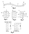
- Fig. 4 shows a top view of the form bracket according to FIG. 1, as is the shaped bracket according to the invention with the rectangular cross section shown in Fig. 3 with relatively large bending moments acting around the y-axis, which Push ends 5, 6 apart, behaves.
- the shaped bracket according to the invention breaks in the y direction, that is to say perpendicular to the bracket plane x, z in an exaggerated S-shaped position, so that in the Bracket 1 is not a pure bending load, but a mixed bending / torsional load prevails.
- Fig. 5 shows an overall cross section 7 according to section A-A in Fig. 1, in which it can be seen that they have a rectangular single cross section Bracket elements 2, 3 are each provided with a coating 10, 11 which preferably made of plastic, e.g. Polyamide.
- FIG. 6 shows an alternative embodiment of the total cross section 7 according to FIG Section A-A in Fig. 1, in which the two bracket elements 2, 3 within one common envelope 12 are arranged. So that the bracket elements 2, 3 also adequately relative to each other in the temple plane in this embodiment x, z can move, the envelope 12 can be made of an elastic Plastic exist and a suitable lubricant in the interface 4 between the bracket elements 2, 3 are introduced.
- Fig. 7 shows a further possibility of holding the bracket elements 2, 3 together.
- the bracket element 2 has at least two mushroom or rivet-shaped Projections 17, which consist of a shaft 18 and a rounded head 19 exist. Between the exposed, facing left in Fig. 7 Annular surface of the head 19 and the bracket element 2 creates an annular space, in which the bracket element 3 can engage, the in the bracket element 3 located bore 20 has a diameter that enough play 21 for a relative movement of the bracket elements 2, 3 in the temple plane. Also the Length of the shaft 18 or the distance between those engaging the bracket element 3 Annular surface of the head 19 from the parting surface 4 is dimensioned such that a relative movement of the bracket elements 2, 3 in the bracket plane x, z not is hindered. To the comfort of the bracket according to this embodiment not to be affected, it is in the relevant item of clothing to incorporate that the heads 19 point away from the wearer's body.
- the shaped bracket according to the invention can also be used without the bracket elements 2, 3 caps 13 fixed to one another at the ends. 5, 6 are formed.
- the shaped brackets according to FIGS. 6 and 7 are in the local z'-direction displaceable against each other without being in the y-direction can separate from each other.
- the embodiments according to FIGS. 3 and 5 in this case must be of the type in the item of clothing concerned provided bracket channel are held together.
- a protective cap are attached, which go sufficiently beyond the respective temple end Offers space around the adjacent end of the bracket element 3 or 2 slidable to record. This ensures that despite unimpeded Relative movement possibility in the z'-direction does not damage the item of clothing becomes.
- FIG 8 shows a comparative comparison of a shaping bracket according to FIG State of the art and a shaped bracket according to the invention.
- the flat rolled one Round wire existing form bracket according to the prior art has the Rectangular cross section shown on the left with the dimensions 0.6 mm x 2 mm on.
- the shaped bracket according to the invention also has the one shown on the right rectangular total cross-section, which is made up of the two identical rectangular Individual cross sections of the bracket elements 2, 3 are composed.
- the rectangular cross section of each bracket element 2, 3 has the dimensions 0.4 mm x 2 mm on.
- the material use in the shaped bracket according to the invention is 33.3% higher than in the known shaped bracket. Because the breaking load under bending stress in the plane x, z is proportional to the width of the material in the y direction, the The shaped bracket according to the invention has a 33.3% higher breaking load, which is according to the invention is desired. The same applies to the deflection in the Temple plane x, z, so that the stiffness in the temple plane x, z by 33.3% is higher, which is also desired according to the invention.
- the two shaped brackets have the same force perpendicular to the bracket level x, z, there is a deflection of the shaped bracket according to the invention, which is 68% greater than the deflection of the shaped bracket according to the stand of the technique. This means that despite the larger overall cross section of the invention Shaped bracket the flexibility perpendicular to the bracket level x, z by 68% is higher than in the known shaped bracket, which is desired according to the invention is.
Landscapes
- Engineering & Computer Science (AREA)
- Textile Engineering (AREA)
- Chemical & Material Sciences (AREA)
- Materials Engineering (AREA)
- Corsets Or Brassieres (AREA)
- Orthopedics, Nursing, And Contraception (AREA)
Description
- Fig. 1:
- eine Aufsicht auf einen erfindungsgemäßen Formbügel,
- Fig. 2:
- eine Seitenansicht des Formbügels gemäß Fig. 1 von rechts,
- Fig. 3:
- mehrere mögliche Gesamt- bzw. Einzelquerschnitte gemäß Schnitt A-A in Fig. 1 erfindungsgemäßer Formbügel bzw. Bügelelemente,
- Fig. 4:
- eine Ansicht des Formbügels gemäß Fig. 1 von oben, wobei die sich bei relativ großen, in.der Bügelebene liegenden Biegekräften einstellende Bügelform übertrieben dargestellt ist,
- Fig. 5:
- einen Gesamtquerschnitt eines erfindungsgemäßen Formbügels, bei welchem die Beschichtung der Bügelelemente gezeigt ist;
- Fig. 6:
- einen Gesamtquerschnitt eines erfindungsgemäßen Formbügels, bei welchem die gemeinsame Umhüllung der Bügelelemente gezeigt ist,
- Fig. 7:
- einen Gesamtquerschnitt eines erfindungsgemäßen Formbügels, bei welchem eine spielbehaftete nietartige Führung gezeigt ist, und
- Fig. 8:
- ein Vergleichsbeispiel zwischen einem Formbügel gemäß Stand der Technik (links gezeigter Querschnitt) und einem erfindungsgemäßen Formbügel (rechts gezeigter Querschnitt).
Claims (19)
- Formbügel für die weibliche Brust haltende Bekleidungsstücke, der einen gebogenen Bügel (1) aufweist, wobei der Bügel (1) aus wenigstens zwei Bügelelementen (2, 3) besteht, welche in der Richtung senkrecht zu der von dem Bügel (1) aufgespannten Ebene (x, z) im wesentlichen hintereinander angeordnet sind,
dadurch gekennzeichnet, daß
die Bügelelemente (2, 3) beidseits des Tiefpunkts (T) des Bügels (1) im wesentlichen die gleiche Krümmung aufweisen. - Formbügel nach Anspruch 1,
dadurch gekennzeichnet, daß
die Bügelelemente (2, 3) wenigstens an einem ihrer Enden (5, 6) aneinander befestigt sind. - Formbügel nach Anspruch 2,
dadurch gekennzeichnet, daß
die Befestigung von einer wenigstens das eine Ende (5, 6) abrundenden Kappe (13) bewirkt wird. - Formbügel nach einem der Ansprüche 1 bis 3,
dadurch gekennzeichnet, daß
die Bügelelemente (2, 3) im Bereich ihrer stärksten Krümmung aneinander befestigt sind. - Formbügel nach einem der vorangehenden Ansprüche,
dadurch gekennzeichnet, daß
die Bügelelemente (2, 3) an mehreren über ihre Länge verteilten Stellen aneinander befestigt sind. - Formbügel nach einem der vorangehenden Ansprüche,
dadurch gekennzeichnet, daß
die zwischen den Bügelelementen (2,3) liegende Trennfläche (4) eben ist. - Formbügel nach Anspruch 6,
dadurch gekennzeichnet, daß
die Trennfläche (4) die Symmetrieebene des Gesamtquerschnitts (7) des Bügels (1) bildet. - Formbügel nach einem der vorangehenden Ansprüche,
dadurch gekennzeichnet, daß
der Gesamtquerschnitt (7) des Bügels (1) eine lange (8) und eine kurze Achse (9) aufweist, wobei die lange Achse (8) im wesentlichen in der von dem Bügel (1) aufgespannten Ebene (x, z) liegt. - Formbügel nach Anspruch 8,
dadurch gekennzeichnet, daß
der Gesamtquerschnitt (7) ein Rechteckquerschnitt ist. - Formbügel nach Anspruch 8,
dadurch gekennzeichnet, daß
der Gesamtquerschnitt (7) ein Doppel-T-Querschnitt ist. - Formbügel nach Anspruch 8,
dadurch gekennzeichnet, daß
der Gesamtquerschnitt (7) ein elliptischer Querschnitt ist. - Formbügel nach einem der vorangehenden Ansprüche,
dadurch gekennzeichnet, daß
die Bügelelemente (2, 3) jeweils eine Beschichtung (10, 11) aufweisen. - Formbügel nach einem der Ansprüche 1 bis 11,
dadurch gekennzeichnet, daß
die Bügelelemente (2, 3) innerhalb einer gemeinsamen Umhüllung (12) angeordnet sind. - Formbügel nach Anspruch 12 oder 13,
dadurch gekennzeichnet, daß
die Beschichtung (10, 11) oder die Umhüllung (12) aus Kunststoff ist. - Formbügel nach einem der Ansprüche 1 bis 14,
dadurch gekennzeichnet, daß
die Bügelelemente (2, 3) mittels einer spielbehafteten nietförmigen Führungseinrichtung (17,18,19) aneinander geführt sind. - Formbügel nach einem der Ansprüche 13, 15 oder 16,
dadurch gekennzeichnet, daß
sich in der Trennfläche (4) ein Gleitmittel befindet. - Formbügel nach einem der vorangehenden Ansprüche,
dadurch gekennzeichnet, daß
die Bügelelemente (2,3) aus Metall sind. - Formbügel nach einem der Ansprüche 1 bis 17,
dadurch gekennzeichnet, daß
die Bügelelemente (2,3) aus Kunststoff sind. - Bekleidungsstück zum Halten der weiblichen Brust, welches wenigstens ein Körbchen aufweist,
dadurch gekennzeichnet, daß
in das wenigstens eine Körbchen ein Formbügel nach einem der vorangehenden Ansprüche eingearbeitet ist.
Applications Claiming Priority (5)
| Application Number | Priority Date | Filing Date | Title |
|---|---|---|---|
| DE19743501 | 1997-10-01 | ||
| DE19743501 | 1997-10-01 | ||
| DE19743684 | 1997-10-02 | ||
| DE19743684A DE19743684C1 (de) | 1997-10-01 | 1997-10-02 | Formbügel |
| PCT/EP1998/006084 WO1999016323A1 (de) | 1997-10-01 | 1998-09-24 | Formbügel |
Publications (2)
| Publication Number | Publication Date |
|---|---|
| EP1018902A1 EP1018902A1 (de) | 2000-07-19 |
| EP1018902B1 true EP1018902B1 (de) | 2001-11-21 |
Family
ID=26040510
Family Applications (1)
| Application Number | Title | Priority Date | Filing Date |
|---|---|---|---|
| EP98952639A Expired - Lifetime EP1018902B1 (de) | 1997-10-01 | 1998-09-24 | Formbügel |
Country Status (5)
| Country | Link |
|---|---|
| US (1) | US6241576B1 (de) |
| EP (1) | EP1018902B1 (de) |
| AU (1) | AU1026499A (de) |
| ES (1) | ES2167952T3 (de) |
| WO (1) | WO1999016323A1 (de) |
Families Citing this family (20)
| Publication number | Priority date | Publication date | Assignee | Title |
|---|---|---|---|---|
| US20050034219A1 (en) * | 2003-08-13 | 2005-02-17 | Melanie Lowry | Thigh-slimming garment and method thereof |
| US6846217B1 (en) | 2003-10-01 | 2005-01-25 | Texas Instruments Incorporated | Garment with interior bra structure with side supports |
| GB0426321D0 (en) * | 2004-12-01 | 2005-01-05 | Lee Sara Corp | A brassiere wire |
| US7887389B1 (en) | 2006-12-15 | 2011-02-15 | A & F Trademark, Inc. | Support pad for an undergarment |
| JP2009136680A (ja) | 2007-12-05 | 2009-06-25 | Medison Co Ltd | 超音波映像を形成する超音波システム及び方法 |
| US8333634B2 (en) | 2009-04-01 | 2012-12-18 | Genie Toys Plc | Frames |
| CN102058166A (zh) * | 2009-11-13 | 2011-05-18 | 安莉芳(中国)服装有限公司 | 文胸罩杯立体支撑圈 |
| WO2012094814A1 (en) * | 2011-01-13 | 2012-07-19 | Regina Miracle International (Group) Limited | Improved support structure for brassiere |
| USD665149S1 (en) * | 2011-02-01 | 2012-08-14 | Suilung Cheung | Bra wire |
| USD687208S1 (en) * | 2011-02-01 | 2013-08-06 | Suilung Cheung | Bra wire |
| USD664736S1 (en) * | 2011-02-01 | 2012-08-07 | Suilung Cheung | Bra wire |
| US20140057529A1 (en) * | 2011-05-23 | 2014-02-27 | Top Form (B.V.I) Limited | Brassiere cup plastic strip support and manufacturing method therefor |
| US20120302134A1 (en) * | 2011-05-23 | 2012-11-29 | Ho Yau Wan | Brassiere Cup Underwire And Manufacturing Method Therefor |
| WO2013078622A1 (en) * | 2011-11-29 | 2013-06-06 | Regina Miracle International (Group) Limited | An underwire for a brassiere |
| US9198468B2 (en) | 2013-02-14 | 2015-12-01 | Victoria's Secret Stores Brand Management, Inc. | Support component for a bra |
| US20140370784A1 (en) * | 2013-06-14 | 2014-12-18 | Bragel International, Inc. | Breast form with underwire and method of manufacturing thereof |
| CN103393226B (zh) * | 2013-07-31 | 2015-05-27 | 开平优丽内衣服装配料有限公司 | 一种女性胸衣托套及其胸衣 |
| CN103549668B (zh) * | 2013-11-13 | 2016-05-11 | 开平鸿汉服装配件有限公司 | 一种异形截面胸衣钢圈 |
| US11058156B2 (en) * | 2018-02-07 | 2021-07-13 | Jacqueline Leverette | Removable underwire for brassieres |
| USD1082216S1 (en) * | 2020-10-29 | 2025-07-08 | Kaiping U-Like Undergarment Accessories Co., Ltd. | Wire for bras |
Family Cites Families (24)
| Publication number | Priority date | Publication date | Assignee | Title |
|---|---|---|---|---|
| DE76647C (de) | F. W. LYON in New-York, V. St. A | Unterlegte oder doppelte Corsetsiange | ||
| US1664926A (en) | 1927-02-16 | 1928-04-03 | Fairy Brassiere Co Inc | Brassiere bust supporter |
| USRE22771E (en) * | 1943-09-21 | 1946-07-16 | Brassiere | |
| US2438062A (en) * | 1945-02-17 | 1948-03-16 | French Look Inc | Lady's garment |
| US2432910A (en) * | 1946-04-25 | 1947-12-16 | Licht Anna | Lady's garment |
| US2530829A (en) * | 1947-02-11 | 1950-11-21 | Licht Anna | Lady's garment |
| US2595088A (en) * | 1947-08-12 | 1952-04-29 | Licht Anna | Brace for lady's garment |
| FR1020640A (fr) * | 1952-09-03 | 1953-02-09 | Soutien-gorge | |
| NL102723C (de) | 1956-09-08 | |||
| US2923300A (en) | 1957-07-25 | 1960-02-02 | Ots Joseph Michel | Reinforcement for brassieres and the like garments for ladies |
| FR1194481A (fr) | 1958-01-23 | 1959-11-10 | Perfectionnements à la confection des sous-vêtements féminins tels que soutien-gorge, bustiers, maillots de bain et analogues | |
| US3114374A (en) | 1960-08-01 | 1963-12-17 | Regina Entpr Inc | Covered wire |
| US3209756A (en) | 1963-03-05 | 1965-10-05 | Rowell Ross Fredrick | Breast frames for brassieres and other garments |
| BE759716A (fr) | 1970-04-03 | 1971-06-02 | S & S Ind Inc | Armatures de soutiens-gorges |
| US3763865A (en) * | 1972-06-01 | 1973-10-09 | Fru A De | Convertible brassiere |
| DE2737415A1 (de) | 1977-08-19 | 1979-02-22 | Joerg Troeger | Miedercorsage |
| DE2750911A1 (de) | 1977-11-14 | 1979-05-17 | Joerg Troeger | Miederkorsage |
| US4153062A (en) | 1978-05-04 | 1979-05-08 | Victoria Delet | Brassiere underwire construction and method |
| US4235240A (en) | 1978-08-21 | 1980-11-25 | Bonnie Enterprises, Inc. | Undergarment reinforcements |
| US5141470A (en) | 1991-09-19 | 1992-08-25 | S&S Industries, Inc. | Monocoque breast supporting frames |
| US5387150A (en) * | 1993-04-14 | 1995-02-07 | Terrell; Linda L. C. | Underwire bra |
| FR2714797B3 (fr) | 1994-01-11 | 1996-04-26 | Christian Santoul | Armature pour soutien-gorge. |
| DE69408173T2 (de) | 1994-01-12 | 1998-11-05 | Bekaert Sa Nv | Versteifungsbügel für damenbekleidung |
| CA2242032C (en) * | 1997-07-09 | 2007-10-30 | Playtex Apparel, Inc. | Framework for the rigidification of a part of garment, made of a thermoplastic or thermosetting material with rigidification longitudinal fibres |
-
1998
- 1998-09-24 WO PCT/EP1998/006084 patent/WO1999016323A1/de not_active Ceased
- 1998-09-24 AU AU10264/99A patent/AU1026499A/en not_active Abandoned
- 1998-09-24 ES ES98952639T patent/ES2167952T3/es not_active Expired - Lifetime
- 1998-09-24 EP EP98952639A patent/EP1018902B1/de not_active Expired - Lifetime
- 1998-09-24 US US09/509,103 patent/US6241576B1/en not_active Expired - Fee Related
Also Published As
| Publication number | Publication date |
|---|---|
| AU1026499A (en) | 1999-04-23 |
| ES2167952T3 (es) | 2002-05-16 |
| US6241576B1 (en) | 2001-06-05 |
| EP1018902A1 (de) | 2000-07-19 |
| WO1999016323A1 (de) | 1999-04-08 |
Similar Documents
| Publication | Publication Date | Title |
|---|---|---|
| EP1018902A1 (de) | Formbügel | |
| EP1082233B1 (de) | Wölbungsverstellbare Stütze, insbesondere Lordosenstütze, für Sitze und Liegen aller Art | |
| DE19942351B4 (de) | Sitztiefeneinstellvorrichtung für einen Fahrzeugsitz | |
| EP0780262B1 (de) | Vorrichtung zur Befestigung eines Stützelements an einem Drahtgitter | |
| DE69225374T2 (de) | Einschalige Brustunterstützung | |
| EP0434660B1 (de) | Anatomisch formbare Stütze | |
| DE19882337B4 (de) | Verstellbares flexibles Stirnband für eine Kopfbedeckung | |
| EP3949780A1 (de) | Kopfaufhängung für eine kopfbedeckung und kopfbedeckung mit einer kopfaufhängung | |
| EP0208273B1 (de) | Bügelendstück für einen Bügel einer Brillenfassung | |
| DE10220028B4 (de) | Sitzeinlage und Verfahren zu ihrer Herstellung | |
| DE2637933B2 (de) | Büstenhalter | |
| DE60312581T2 (de) | Weblitze und Verfahren zu ihrer Herstellung, Fachbildungsvorrichtung und Webmaschine mit einer solchen Weblitze | |
| DE3446184C2 (de) | Bügelendstück für einen Bügel einer Brillenfassung | |
| DE19743684C1 (de) | Formbügel | |
| EP1053692B1 (de) | Bügelanordnung für Büstenhalter | |
| DE2349381B2 (de) | Blattfeder | |
| DE969556C (de) | Brille mit nicht-metallischen Ohrenbuegeln | |
| EP3047745A1 (de) | Büstenhalter mit magnetverschluss | |
| DE688758C (de) | Gummizugfeder, insbesondere fuer Kraftfahrzeuge | |
| AT166413B (de) | Nichtmetallisches Brillengestell mit federnden Seitenbügeln | |
| EP0259561B1 (de) | Gebiss für Pferde | |
| DE19748656C1 (de) | Formbügel mit kelchförmigem Querschnitt | |
| EP1369018B1 (de) | Förderband | |
| EP0546506B1 (de) | Stützeinrichtung, insbesondere für einen Büstenhalter | |
| AT406221B (de) | Wölbungsverstellbare stütze, insbesondere lordosenstütze, für sitze und liegen aller art |
Legal Events
| Date | Code | Title | Description |
|---|---|---|---|
| PUAI | Public reference made under article 153(3) epc to a published international application that has entered the european phase |
Free format text: ORIGINAL CODE: 0009012 |
|
| 17P | Request for examination filed |
Effective date: 20000316 |
|
| AK | Designated contracting states |
Kind code of ref document: A1 Designated state(s): ES FR GB IT |
|
| GRAG | Despatch of communication of intention to grant |
Free format text: ORIGINAL CODE: EPIDOS AGRA |
|
| 17Q | First examination report despatched |
Effective date: 20010618 |
|
| GRAG | Despatch of communication of intention to grant |
Free format text: ORIGINAL CODE: EPIDOS AGRA |
|
| GRAH | Despatch of communication of intention to grant a patent |
Free format text: ORIGINAL CODE: EPIDOS IGRA |
|
| GRAA | (expected) grant |
Free format text: ORIGINAL CODE: 0009210 |
|
| AK | Designated contracting states |
Kind code of ref document: B1 Designated state(s): ES FR GB IT |
|
| REG | Reference to a national code |
Ref country code: GB Ref legal event code: IF02 |
|
| GBT | Gb: translation of ep patent filed (gb section 77(6)(a)/1977) |
Effective date: 20020216 |
|
| REG | Reference to a national code |
Ref country code: ES Ref legal event code: FG2A Ref document number: 2167952 Country of ref document: ES Kind code of ref document: T3 |
|
| PLBE | No opposition filed within time limit |
Free format text: ORIGINAL CODE: 0009261 |
|
| STAA | Information on the status of an ep patent application or granted ep patent |
Free format text: STATUS: NO OPPOSITION FILED WITHIN TIME LIMIT |
|
| 26N | No opposition filed | ||
| PGFP | Annual fee paid to national office [announced via postgrant information from national office to epo] |
Ref country code: ES Payment date: 20080922 Year of fee payment: 11 |
|
| PGFP | Annual fee paid to national office [announced via postgrant information from national office to epo] |
Ref country code: IT Payment date: 20080924 Year of fee payment: 11 Ref country code: FR Payment date: 20080917 Year of fee payment: 11 |
|
| PGFP | Annual fee paid to national office [announced via postgrant information from national office to epo] |
Ref country code: GB Payment date: 20080922 Year of fee payment: 11 |
|
| GBPC | Gb: european patent ceased through non-payment of renewal fee |
Effective date: 20090924 |
|
| REG | Reference to a national code |
Ref country code: FR Ref legal event code: ST Effective date: 20100531 |
|
| PG25 | Lapsed in a contracting state [announced via postgrant information from national office to epo] |
Ref country code: FR Free format text: LAPSE BECAUSE OF NON-PAYMENT OF DUE FEES Effective date: 20090930 |
|
| PG25 | Lapsed in a contracting state [announced via postgrant information from national office to epo] |
Ref country code: GB Free format text: LAPSE BECAUSE OF NON-PAYMENT OF DUE FEES Effective date: 20090924 |
|
| PG25 | Lapsed in a contracting state [announced via postgrant information from national office to epo] |
Ref country code: IT Free format text: LAPSE BECAUSE OF NON-PAYMENT OF DUE FEES Effective date: 20090924 |
|
| REG | Reference to a national code |
Ref country code: ES Ref legal event code: FD2A Effective date: 20110718 |
|
| PG25 | Lapsed in a contracting state [announced via postgrant information from national office to epo] |
Ref country code: ES Free format text: LAPSE BECAUSE OF NON-PAYMENT OF DUE FEES Effective date: 20110706 |
|
| PG25 | Lapsed in a contracting state [announced via postgrant information from national office to epo] |
Ref country code: ES Free format text: LAPSE BECAUSE OF NON-PAYMENT OF DUE FEES Effective date: 20090925 |