EP1018732B1 - Informationswiedergabeverfahren und -gerät - Google Patents
Informationswiedergabeverfahren und -gerät Download PDFInfo
- Publication number
- EP1018732B1 EP1018732B1 EP99126087A EP99126087A EP1018732B1 EP 1018732 B1 EP1018732 B1 EP 1018732B1 EP 99126087 A EP99126087 A EP 99126087A EP 99126087 A EP99126087 A EP 99126087A EP 1018732 B1 EP1018732 B1 EP 1018732B1
- Authority
- EP
- European Patent Office
- Prior art keywords
- equalization
- information
- coefficient
- signal
- reproducing
- Prior art date
- Legal status (The legal status is an assumption and is not a legal conclusion. Google has not performed a legal analysis and makes no representation as to the accuracy of the status listed.)
- Expired - Lifetime
Links
- 238000000034 method Methods 0.000 title claims description 17
- 230000003287 optical effect Effects 0.000 claims description 61
- 230000008859 change Effects 0.000 claims description 15
- 238000001514 detection method Methods 0.000 claims description 8
- 230000001276 controlling effect Effects 0.000 claims 1
- 230000001105 regulatory effect Effects 0.000 claims 1
- 238000010586 diagram Methods 0.000 description 7
- 230000006870 function Effects 0.000 description 3
- 238000004088 simulation Methods 0.000 description 3
- 238000004364 calculation method Methods 0.000 description 2
- 230000003247 decreasing effect Effects 0.000 description 2
- 230000003111 delayed effect Effects 0.000 description 2
- 230000000694 effects Effects 0.000 description 2
- 230000006872 improvement Effects 0.000 description 2
- 230000002123 temporal effect Effects 0.000 description 2
- 238000013459 approach Methods 0.000 description 1
- 230000006866 deterioration Effects 0.000 description 1
- 230000008569 process Effects 0.000 description 1
- 238000003672 processing method Methods 0.000 description 1
- 230000009467 reduction Effects 0.000 description 1
Images



Classifications
-
- G—PHYSICS
- G11—INFORMATION STORAGE
- G11B—INFORMATION STORAGE BASED ON RELATIVE MOVEMENT BETWEEN RECORD CARRIER AND TRANSDUCER
- G11B20/00—Signal processing not specific to the method of recording or reproducing; Circuits therefor
- G11B20/10—Digital recording or reproducing
- G11B20/10009—Improvement or modification of read or write signals
-
- G—PHYSICS
- G11—INFORMATION STORAGE
- G11B—INFORMATION STORAGE BASED ON RELATIVE MOVEMENT BETWEEN RECORD CARRIER AND TRANSDUCER
- G11B7/00—Recording or reproducing by optical means, e.g. recording using a thermal beam of optical radiation by modifying optical properties or the physical structure, reproducing using an optical beam at lower power by sensing optical properties; Record carriers therefor
- G11B7/004—Recording, reproducing or erasing methods; Read, write or erase circuits therefor
- G11B7/005—Reproducing
-
- G—PHYSICS
- G11—INFORMATION STORAGE
- G11B—INFORMATION STORAGE BASED ON RELATIVE MOVEMENT BETWEEN RECORD CARRIER AND TRANSDUCER
- G11B20/00—Signal processing not specific to the method of recording or reproducing; Circuits therefor
- G11B20/10—Digital recording or reproducing
Definitions
- This invention relates to an information reproducing method for reproducing information recorded on an optical recording medium by using a laser beam, and to an apparatus for executing this method.
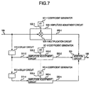
- the reproducing signal 104 is multiplied by C1 by a multiplication circuit 505-1 contained in the amplitude adjustment circuit 500-1, and is outputted as a signal-after-amplitude adjustment 520-1.
- the reproducing signal 104 inputted to the delay circuit 510-2 is delayed by a predetermined delay amount and is converted to a signal-after-delay 511-2.
- the equalization processing comprises a plurality of processing as shown in Fig. 7, and is therefore executed serially. In consequence, signals-after-amplitude adjustment 520-1 to 520-n, each receiving an intrinsic delay amount and an intrinsic amplitude change, are acquired.
- the diameter of the optical spot used for reproduction is defined substantially as ⁇ /NA by the wavelength ⁇ of the laser beam and the numerical aperture NA of the objective lens, as described above.
- the highest temporal frequency that can be reproduced is (4 x NA)/ ⁇ .
- the frequency of the highest density repetition signal recorded approaches the temporal frequency, the signal amplitude in reproduction becomes smaller, and reproduction becomes more difficult. Therefore, when the high density is achieved by reducing the mark pitch, the highest density repetition signal involves deterioration of a signal-to-noise ratio (S/N) resulting from the drop of the amplitude, and reproduction accuracy drops.
- S/N signal-to-noise ratio
- JP-A-10-112031 discloses a method for calculating equalization coefficients in an optical disk device. The method scans a predetermined mark train recorded in a special area of the disk. Optimised equalization coefficients are calculated from a signal reproduced from the predetermined mark train and are then used on other areas of the disk.
- the equalization processing is executed using equalization coefficients that have a large absolute value in order to reduce the inter-symbol interference generated by the continuation of short marks and short non-recorded portions, and to increase the amplitude of the highest density repetition signal.
- the equalization coefficient for reducing the edge shift is different between the highest density repetition signal and other signals. For this reason, the equalization processing using the equalization coefficient that is kept fixed at a predetermined value cannot increase the amplitude of the highest density repetition signal while keeping the inter-symbol interference at a low level.
- Fig. 3 is a circuit diagram showing an example of a non-linear equalization circuit 107 according to the present invention.
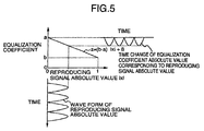
- Amplitude adjustment circuits 160-01 to 160-03 adjust the amplitude of a reproducing signal 106 in accordance with the rule shown in Fig. 5. As a result, a portion having a small amplitude is adjusted to a large amplitude and is outputted. A portion having a large amplitude is converted to a small amplitude and is outputted.
- Coefficient generators 210-1 to 210-3 give the maximum value a shown in Fig. 5 of coefficients a1 to a3 and give the minimum value b shown in Fig. 5 among the coefficients b1 to b3.
- reference numerals 161-1, 161-2 and 161-3 denote signals-after-amplitude adjustment.
- Reference numeral 151-2 and 151-3 denote signals-after-delay.
- Reference numerals 211-1, 211-2 and 211-3 denote the maximum value signals of the coefficients, and reference numerals 212-1, 212-2 and 212-3 denote the minimum value signals of the coefficients.
- Reference numerals 213-1, 213-2 and 213-3 denote polarity signals.
- Reference numeral 170 denotes an addition circuit and reference numeral 108 denotes a signal-after-equalization.
- reference numerals 161-1 to 161-5 denote signals-after-amplitude adjustment.
- Reference numerals 151-2 to 151-5 denote signals-after-delay.
- Reference numerals 211-1 to 211-5 denote the maximum values of the coefficients and reference numerals 212-1 to 212-5 denote the minimum values of the coefficients.
- Reference numerals 213-1 to 213-5 denote polarity signals.
- Reference numeral 106 denotes a reproduction signal.
- Reference numeral 170 denotes an addition circuit and reference numeral 108 denotes a signal-after- equalization.
- the amplitude of the highest density repetition signal can be improved without increasing the edge shift. Because the S/N can be improved eventually, the high density can be achieved by decreasing the mark pitch.
- the reproducing signal-after-amplitude adjustment 106 is delayed by the delay amount set in advance by the delay circuit 150-2 and is converted to the reproducing signal-after-delay and gain adjustment 151-2.
- This signal is processed by the amplitude adjustment circuit 160-2 in the same way as described above, and the signal-after-amplitude adjustment 161-2 is generated. Therefore, each of the signals 161-1 to 161-n generated by each amplitude adjustment circuit is the signal to which an intrinsic delay amount and intrinsic amplitude adjustment are imparted.
- Fig. 4 shows an example of a 5-tap non-linear equalization circuit according to the present system.
- Fig. 6E shows the eye pattern when the coefficients a1, b1 and 1 in Fig. 4 are set to 1.0, 0.3 and -1, respectively, the coefficients a2, b2 and c2 are set to 1.0, 0.3 and +1, respectively, the coefficients a3, b3 and c3 are set to 1.0, 1.0 and +1, respectively, the coefficients a4, b4 and c4 are set to 1.0, 0.3 and +1, and the coefficients a5, b5 and c5 are set to 1.0, 0.3 and -1, respectively, and the delay amount by the delay circuit is equal to the detection window width. It can be seen that the amplitude of the highest repetition signal is improved most greatly in each eye pattern shown in Figs. 6A-6E.
- the amplitude of the highest density repetition signal can be increased according to the equalization processing of the present invention without increasing the edge shift. Because the S/N can be eventually improved, high reliability can be secured and the high density can be achieved even when the mark pitch is reduced.
- the present invention applies the signal processing, that reduces the inter-symbol interference by serially changing the equalization coefficients in accordance with the level of the reproducing signals, to the reproducing signals, and can increase the amplitude of the highest density repetition signal without increasing the edge shift. Therefore, since the S/N can be improved, high reliability can be secured even when the mark pitch is decreased, and the high density can be achieved. Additionally, the equalization processing according to the present invention can be applied to not only the phase-change optical disk but also the opto-magnetic disk.
Landscapes
- Engineering & Computer Science (AREA)
- Signal Processing (AREA)
- Optical Recording Or Reproduction (AREA)
- Signal Processing For Digital Recording And Reproducing (AREA)
Claims (13)
- Verfahren zur Wiedergabe von Informationen durch Abtasten von auf Spuren eines Aufzeichnungsmediums (100) aufgezeichneten Informationsmarkierungen mittels eines optischen Flecks (103), Erfassen einer optischen Änderung von den Informationsmarkierungen durch den Abtastvorgang, Bearbeiten eines vom Erfassungsvorgang erhaltenen Wiedergabesignals (104), um eine Intersymbol-Interferenz mit von Informationsmarkierung zu Informationsmarkierung variierendem Interferenzbetrag zu verringern, und Wiedergeben der von den Informationsmarkierungen dargestellten Information, mit folgenden Schritten:a) Erfassen eines Pegels des Wiedergabesignals als Angabe für die Größe der Informationsmarkierung,b) Berechnen mehrerer Ausgleichskoeffizienten (191-1 bis 191-n) für eine Ausgleichsbearbeitung des Wiedergabesignals, wobei die Größe eines Ausgleichskoeffizienten für eine Informationsmarkierung in umgekehrter Beziehung zum Pegel des Wiedergabesignals dieser Informationsmarkierung steht, undc) Verringern der Intersymbol-Interferenz durch eine Ausgleichsbearbeitung des Wiedergabesignals unter Verwendung der Ausgleichskoeffizienten.
- Verfahren nach Anspruch 1, wobei die Erfassung des Pegels des Wiedergabesignals in Schritt a) die Erzeugung eines Absolutwerts |x| des Wiedergabesignals beinhaltet.
- Verfahren nach Anspruch 2, wobei die Erfassung des Pegels des Wiedergabesignals in Schritt a) die Erzeugung eines Absolutwerts |x - x0| des Wiedergabesignals beinhaltet und x0 eine Asymmetrie ist, die ein mittlerer Gleichstrompegel des Wiedergabesignals (3Tw) der höchsten Dichte ist.
- Verfahren nach Anspruch 1, wobei der Ausgleichskoeffizient z in Schritt b) aus dem funktionalen Ausdruck z = f (|x|) berechnet wird und f eine Konstante darstellt, die von einem vorbestimmten Koeffizienten bestimmt wird.
- Verfahren nach Anspruch 1, wobei der Ausgleichskoeffizient in Schritt b) aus dem funktionalen Ausdruck z = f|x - x0| berechnet wird, wobei f eine Konstante darstellt, die von einem vorbestimmten Koeffizienten bestimmt ist, und eine Asymmetrie x0 ein mittlerer Gleichstrompegel des Wiedergabesignals (3Tw) höchster Dichte ist.
- Verfahren nach Anspruch 1, wobei der für die Ausgleichsbearbeitung für eine erste Informationsmarkierung zur Verringerung der Intersymbol-Interferenz in Schritt c) verwendete Ausgleichskoeffizient von dem für die Ausgleichsbearbeitung für eine zweite Informationsmarkierung, die länger als die erste Informationsmarkierung ist, verwendeten Ausgleichskoeffizienten verschieden ist.
- Verfahren nach Anspruch 1, wobei der zur Ausgleichsbearbeitung für eine erste Informationsmarkierung zur Verringerung der Intersymbol-Interferenz in Schritt c) verwendete Ausgleichskoeffizient größer als der zur Ausgleichsbearbeitung für eine zweite Informationsmarkierung, die länger als die erste Informationsmarkierung ist, verwendete Ausgleichskoeffizient ist.
- Informationswiedergabevorrichtung zur Wiedergabe von Information durch Abtasten von auf Spuren eines Aufzeichnungsmediums (100) aufgezeichneten Informationsmarkierungen mittels eines optischen Flecks (103), aufweisenddadurch gekennzeichnet, daß die Ausgleichsschaltung (107) eingerichtet ist, Ausgleichskoeffizienten (191-1 bis 191-n) zu erzeugen, wobei die Größe eines Ausgleichskoeffizienten für eine Informationsmarkierung in umgekehrter Beziehung zum Pegel des Signals für die optische Änderung dieser Informationsmarkierung steht, und die so berechneten Ausgleichskoeffizienten für die Ausgleichsbearbeitung zu verwenden.einen optischen Kopf (102) zum Projizieren des optischen Flecks (103) auf die Informationsmarkierungen, um die Information zu lesen, zum Erfassen einer optischen Änderung von jeder Informationsmarkierung und zum Ausgeben eines Signals für die optische Änderung,eine Ausgleichsschaltung (107) zur Durchführung einer Ausgleichsbearbeitung, um eine Intersymbol-Interferenz in dem Signal für die optische Änderung zu verringern, undeine Datendemodulationsschaltung (111) zum Demodulieren des Signals für die optische Änderung, das der Ausgleichsbearbeitung unterworfen wurde,
- Vorrichtung nach Anspruch 8, aufweisendeine Antriebseinrichtung (101) zum Drehen des optischen Aufzeichnungsmediums (100),eine Kopfantriebseinrichtung (113), um den optischen Kopf (102) relativ zu dem optischen Aufzeichnungsmedium (100) anzutreiben, so daß der optische Fleck (103) die Informationsmarkierungen abtastet,eine Laseransteuereinrichtung (115) zum Steuern des von dem optischen Kopf (102) projizierten optischen Flecks (103),eine automatische Verstärkungssteuerschaltung (195) zum Regeln der Amplitude des vom optischen Kopf (102) erfaßten Signals für die optische Änderung auf eine vorbestimmte Amplitude, undeine phasenverschränkte Schleifenschaltung (109) zur Erzeugung eines Synchronisationssignals (110) synchron zur Drehung des optischen Aufzeichnungsmediums (100) aufgrund des der Ausgleichbearbeitung unterworfenen Signals für die optische Änderung, wobei die Datendemodulationsschaltung (111) aufgrund des Synchronisationssignals (110) entsprechend einer vorbestimmten Polaritätsregel arbeitet.
- Vorrichtung nach Anspruch 9, wobei die nicht-lineare Ausgleichsschaltung (107) mehrere Amplitudeneinstellschaltungen (160-1 bis 160-n) zum Einstellen der Amplitude des der Verstärkungssteuerung unterworfenen Signals für die optische Änderung enthält.
- Vorrichtung nach Anspruch 10, wobei jede Amplitudeneinstellschaltung (160-1 bis 160-n) aufweist:eine Absolutwerterzeugungsschaltung (180-1 bis 180-n) zur Erzeugung eines Absolutwerts |x| des Pegels des der Verstärkungssteuerung unterworfenen Signals für die optische Änderung,einen Koeffizientengenerator (210-1 bis 210-n) zur Ausgabe eines Polaritätskoeffizienten (213-1) und Bestimmung eines Maximalkoeffizienten (211-1), eines Minimalkoeffizienten (212-1) und einer Polarität entsprechend dem Maximalwert und dem Minimalwert der Amplitude des von der automatischen Verstärkungssteuerschaltung (105) eingestellten Signals für die optische Änderung,eine erste Multiplikationsschaltung (190-1) zur Erzeugung eines Ausgleichskoeffizienten entsprechend dem Absolutwert |x| aufgrund des Maximalkoeffizienten und des Minimalkoeffizienten, die von dem Koeffizientengenerator (210-1 bis 210-n) vorgegeben sind,eine Polaritätsschaltung (220-1) zum Empfang des Ausgleichskoeffizienten von der Multiplikationschaltung und des Symbolkoeffizienten von dem Koeffizientengenerator, um dem empfangenen Ausgleichskoeffizienten eine Polarität zu geben, um einen Ausgleichskoeffizienten mit Vorzeichen (221-1) zu erzeugen, undeine zweite Multiplikationsschaltung (200-1) zur Erzeugung eines amplitudeneingestellten Signals aus dem Signal für die optische Änderung, das einer Verstärkungssteuerung unterworfen wurde, nach einer Verzögerung und aus dem Ausgleichskoeffizienten mit Vorzeichen (221-1).
- Vorrichtung nach Anspruch 11, wobei die Absolutwerterzeugungsschaltung (180-1) einen Absolutwert |x - x0| erzeugt, der eine Asymmetrie x0 des Absolutwerts |x| der Größe des der Verstärkungssteuerung unterworfenen Signals für die optische Änderung für das Signal (3Tw) höchster Dichte wiedergibt.
- Vorrichtung nach Anspruch 11, wobei die erste Multiplikationsschaltung (130-1) einen Ausgleichskoeffizienten (191-1) entsprechend dem Absolutwert |x - x0| aufgrund des Maximalkoeffizienten (211-1) und des Minimalkoeffizienten (212-1) erzeugt, die von dem Koeffizientengenerator (210-1 bis 210-n) vorgegeben sind.
Applications Claiming Priority (2)
| Application Number | Priority Date | Filing Date | Title |
|---|---|---|---|
| JP00167299A JP3781911B2 (ja) | 1999-01-07 | 1999-01-07 | 情報再生方法及び装置 |
| JP167299 | 1999-01-07 |
Publications (3)
| Publication Number | Publication Date |
|---|---|
| EP1018732A2 EP1018732A2 (de) | 2000-07-12 |
| EP1018732A3 EP1018732A3 (de) | 2001-07-18 |
| EP1018732B1 true EP1018732B1 (de) | 2003-07-30 |
Family
ID=11508022
Family Applications (1)
| Application Number | Title | Priority Date | Filing Date |
|---|---|---|---|
| EP99126087A Expired - Lifetime EP1018732B1 (de) | 1999-01-07 | 1999-12-28 | Informationswiedergabeverfahren und -gerät |
Country Status (6)
| Country | Link |
|---|---|
| US (5) | US6480447B1 (de) |
| EP (1) | EP1018732B1 (de) |
| JP (1) | JP3781911B2 (de) |
| KR (1) | KR100570237B1 (de) |
| DE (1) | DE69909955T2 (de) |
| TW (1) | TW455866B (de) |
Families Citing this family (38)
| Publication number | Priority date | Publication date | Assignee | Title |
|---|---|---|---|---|
| JP3781911B2 (ja) * | 1999-01-07 | 2006-06-07 | 株式会社日立製作所 | 情報再生方法及び装置 |
| US6678230B2 (en) * | 2000-10-31 | 2004-01-13 | Matsushita Electric Industrial Co., Ltd. | Waveform equalizer for a reproduction signal obtained by reproducing marks and non-marks recorded on a recording medium |
| KR100416265B1 (ko) | 2001-12-11 | 2004-01-24 | 삼성전자주식회사 | 출력신호의 부호와 절대값을 이용하여 그 동작을 제어하는적응형 등화기 |
| JP3647817B2 (ja) * | 2002-03-26 | 2005-05-18 | 松下電器産業株式会社 | 等化器および等化方法 |
| CN1842859A (zh) * | 2003-08-27 | 2006-10-04 | 皇家飞利浦电子股份有限公司 | 用于数据存储系统的读取均衡器 |
| US7532425B2 (en) * | 2005-06-21 | 2009-05-12 | Fujifilm Corporation | Reproducing method, reproducing apparatus, recording and reproducing apparatus, and magnetic recording medium |
| US8389048B2 (en) | 2006-02-10 | 2013-03-05 | Showa Denko K.K. | Magnetic recording medium, method for production thereof and magnetic recording and reproducing device |
| JP5202340B2 (ja) | 2006-03-24 | 2013-06-05 | ジェネラル・インスツルメント・コーポレーション | ネットワークにおける論理チャネルを構成するための装置、方法、およびコンピュータ読取可能な記録媒体 |
| US9088355B2 (en) | 2006-03-24 | 2015-07-21 | Arris Technology, Inc. | Method and apparatus for determining the dynamic range of an optical link in an HFC network |
| US8537972B2 (en) | 2006-12-07 | 2013-09-17 | General Instrument Corporation | Method and apparatus for determining micro-reflections in a network |
| JP4580380B2 (ja) | 2006-12-28 | 2010-11-10 | 株式会社日立製作所 | 光ディスク装置 |
| JP5320567B2 (ja) * | 2007-03-29 | 2013-10-23 | 独立行政法人国立高等専門学校機構 | 光ディスク用再生等化方法および再生等化回路 |
| US8107329B1 (en) | 2007-07-05 | 2012-01-31 | Marvell International Ltd. | Optical storage system having differential phase detector |
| TWI390506B (zh) * | 2009-05-20 | 2013-03-21 | Novatek Microelectronics Corp | 資料復原之校正電路與方法 |
| TWI391918B (zh) * | 2009-06-15 | 2013-04-01 | Novatek Microelectronics Corp | 資料復原裝置與方法 |
| US8516532B2 (en) * | 2009-07-28 | 2013-08-20 | Motorola Mobility Llc | IP video delivery using flexible channel bonding |
| US8526485B2 (en) | 2009-09-23 | 2013-09-03 | General Instrument Corporation | Using equalization coefficients of end devices in a cable television network to determine and diagnose impairments in upstream channels |
| US8416697B2 (en) | 2010-02-05 | 2013-04-09 | Comcast Cable Communications, Llc | Identification of a fault |
| US8971394B2 (en) | 2010-02-05 | 2015-03-03 | Comcast Cable Communications, Llc | Inducing response signatures in a communication network |
| US8654640B2 (en) | 2010-12-08 | 2014-02-18 | General Instrument Corporation | System and method for IP video delivery using distributed flexible channel bonding |
| US8937992B2 (en) | 2011-08-30 | 2015-01-20 | General Instrument Corporation | Method and apparatus for updating equalization coefficients of adaptive pre-equalizers |
| US8576705B2 (en) | 2011-11-18 | 2013-11-05 | General Instrument Corporation | Upstream channel bonding partial service using spectrum management |
| US9113181B2 (en) | 2011-12-13 | 2015-08-18 | Arris Technology, Inc. | Dynamic channel bonding partial service triggering |
| US8837302B2 (en) | 2012-04-27 | 2014-09-16 | Motorola Mobility Llc | Mapping a network fault |
| US8868736B2 (en) | 2012-04-27 | 2014-10-21 | Motorola Mobility Llc | Estimating a severity level of a network fault |
| US8867371B2 (en) | 2012-04-27 | 2014-10-21 | Motorola Mobility Llc | Estimating physical locations of network faults |
| US9003460B2 (en) | 2012-04-27 | 2015-04-07 | Google Technology Holdings LLC | Network monitoring with estimation of network path to network element location |
| US9065731B2 (en) | 2012-05-01 | 2015-06-23 | Arris Technology, Inc. | Ensure upstream channel quality measurement stability in an upstream channel bonding system using T4 timeout multiplier |
| US9136943B2 (en) | 2012-07-30 | 2015-09-15 | Arris Technology, Inc. | Method of characterizing impairments detected by equalization on a channel of a network |
| US9137164B2 (en) | 2012-11-15 | 2015-09-15 | Arris Technology, Inc. | Upstream receiver integrity assessment for modem registration |
| US9015786B2 (en) | 2012-12-03 | 2015-04-21 | Comcast Cable Communications, Llc | Noise ingress detection |
| US9203639B2 (en) | 2012-12-27 | 2015-12-01 | Arris Technology, Inc. | Dynamic load balancing under partial service conditions |
| US9380475B2 (en) | 2013-03-05 | 2016-06-28 | Comcast Cable Communications, Llc | Network implementation of spectrum analysis |
| US9444719B2 (en) | 2013-03-05 | 2016-09-13 | Comcast Cable Communications, Llc | Remote detection and measurement of data signal leakage |
| US9197886B2 (en) | 2013-03-13 | 2015-11-24 | Arris Enterprises, Inc. | Detecting plant degradation using peer-comparison |
| US9042236B2 (en) | 2013-03-15 | 2015-05-26 | Arris Technology, Inc. | Method using equalization data to determine defects in a cable plant |
| US10477199B2 (en) | 2013-03-15 | 2019-11-12 | Arris Enterprises Llc | Method for identifying and prioritizing fault location in a cable plant |
| US9025469B2 (en) | 2013-03-15 | 2015-05-05 | Arris Technology, Inc. | Method for estimating cable plant topology |
Family Cites Families (26)
| Publication number | Priority date | Publication date | Assignee | Title |
|---|---|---|---|---|
| EP0375342B1 (de) * | 1988-12-21 | 1995-02-15 | Matsushita Electric Industrial Co., Ltd. | Datenaufzeichnungs-wiedergabegerät auf einer Aufzeichnungsscheibe |
| US5418770A (en) * | 1990-06-29 | 1995-05-23 | Hitachi, Ltd. | Method of and apparatus for correcting edge interval of pit in optical recording/read-out apparatus |
| US5297165A (en) * | 1990-07-06 | 1994-03-22 | Nippon Telegraph And Telephone Corporation | Equalizer for radio receive signal |
| JPH0520614A (ja) | 1991-07-10 | 1993-01-29 | Canon Inc | 波形等化装置 |
| JP3005090B2 (ja) * | 1991-10-23 | 2000-01-31 | 株式会社リコー | 学習型波形等化器 |
| EP0569597B1 (de) | 1991-11-20 | 1998-07-15 | Sony Corporation | Gerät für optische platten |
| US5881039A (en) * | 1993-03-09 | 1999-03-09 | Matsushita Electric Industrial Co., Ltd. | Signal processing device for an optical information reproducing apparatus |
| JP3094726B2 (ja) * | 1993-04-02 | 2000-10-03 | 松下電器産業株式会社 | 波形等化方法及び波形等化器 |
| JP3224181B2 (ja) * | 1993-11-09 | 2001-10-29 | 富士通株式会社 | 光ディスクからのデータ再生システム |
| JPH07169055A (ja) * | 1993-12-15 | 1995-07-04 | Hitachi Ltd | 光ディスク装置及び光ディスク |
| US5761172A (en) * | 1994-03-25 | 1998-06-02 | Hitachi, Ltd. | Method of optical reproduction using pulsed light |
| US5898654A (en) | 1994-07-14 | 1999-04-27 | Matsushita Electric Industrial Co., Ltd. | Optical disk and optical disk apparatus having a predetermined pattern of marks on tracks such that a reproduced signal is caused to jitter |
| KR100300954B1 (ko) * | 1994-09-27 | 2001-10-22 | 윤종용 | 고정각속도방식의디스크재생장치의적응형등화기 |
| JPH08124167A (ja) * | 1994-10-19 | 1996-05-17 | Hitachi Ltd | 光学的情報記録再生方法及び装置 |
| JPH08129789A (ja) | 1994-10-31 | 1996-05-21 | Olympus Optical Co Ltd | 光磁気記録用再生回路 |
| US5808988A (en) * | 1995-02-15 | 1998-09-15 | Hitachi, Ltd. | Reproduction of optical information by one-beam optics with reduced crosstalk as recorded in multi-phases and multi-levels at staggered lattice points, and apparatus and recording medium therefor |
| JP3453002B2 (ja) | 1995-04-21 | 2003-10-06 | 富士通株式会社 | 自動調整方法、再生装置及び記憶装置 |
| JPH0944983A (ja) * | 1995-07-28 | 1997-02-14 | Pioneer Electron Corp | 記録情報再生装置 |
| US5757758A (en) | 1995-12-19 | 1998-05-26 | Konica Corporation | Optical pickup apparatus objective lens and converging optical system for optical pickup and optical disk apparatus |
| JP3800653B2 (ja) | 1995-12-26 | 2006-07-26 | ソニー株式会社 | クロストーク除去装置 |
| KR0179258B1 (ko) * | 1996-01-05 | 1999-04-15 | 구자홍 | 광디스크 기록재생장치 |
| JP2853650B2 (ja) * | 1996-04-19 | 1999-02-03 | 日本電気株式会社 | 信号処理装置 |
| JP3776530B2 (ja) * | 1996-09-30 | 2006-05-17 | 株式会社東芝 | 光学的情報再生装置 |
| JPH10112031A (ja) * | 1996-10-04 | 1998-04-28 | Hitachi Ltd | 光学的情報記録再生方法及び装置 |
| US5999349A (en) * | 1996-12-30 | 1999-12-07 | Daewoo Electronics Co., Ltd. | Waveform equalization apparatus |
| JP3781911B2 (ja) * | 1999-01-07 | 2006-06-07 | 株式会社日立製作所 | 情報再生方法及び装置 |
-
1999
- 1999-01-07 JP JP00167299A patent/JP3781911B2/ja not_active Expired - Lifetime
- 1999-12-27 TW TW088123050A patent/TW455866B/zh not_active IP Right Cessation
- 1999-12-28 EP EP99126087A patent/EP1018732B1/de not_active Expired - Lifetime
- 1999-12-28 DE DE69909955T patent/DE69909955T2/de not_active Expired - Lifetime
-
2000
- 2000-01-06 US US09/478,343 patent/US6480447B1/en not_active Expired - Lifetime
- 2000-01-06 KR KR1020000000391A patent/KR100570237B1/ko not_active Expired - Fee Related
-
2002
- 2002-02-14 US US10/074,049 patent/US6552977B2/en not_active Expired - Lifetime
- 2002-10-30 US US10/283,143 patent/US6944105B2/en not_active Expired - Lifetime
-
2003
- 2003-11-19 US US10/715,387 patent/US7046595B2/en not_active Expired - Lifetime
- 2003-11-19 US US10/715,378 patent/US7079457B2/en not_active Expired - Lifetime
Also Published As
| Publication number | Publication date |
|---|---|
| US20040100882A1 (en) | 2004-05-27 |
| US7046595B2 (en) | 2006-05-16 |
| KR100570237B1 (ko) | 2006-04-12 |
| US6480447B1 (en) | 2002-11-12 |
| US20030147318A1 (en) | 2003-08-07 |
| US20040100881A1 (en) | 2004-05-27 |
| US6552977B2 (en) | 2003-04-22 |
| JP2000200463A (ja) | 2000-07-18 |
| TW455866B (en) | 2001-09-21 |
| EP1018732A3 (de) | 2001-07-18 |
| KR20000053396A (ko) | 2000-08-25 |
| JP3781911B2 (ja) | 2006-06-07 |
| US7079457B2 (en) | 2006-07-18 |
| DE69909955T2 (de) | 2004-06-03 |
| US20020080696A1 (en) | 2002-06-27 |
| EP1018732A2 (de) | 2000-07-12 |
| US6944105B2 (en) | 2005-09-13 |
| DE69909955D1 (de) | 2003-09-04 |
Similar Documents
| Publication | Publication Date | Title |
|---|---|---|
| EP1018732B1 (de) | Informationswiedergabeverfahren und -gerät | |
| US5809004A (en) | Information recording medium with pits edges shifted in a step-wise fashion | |
| US5517481A (en) | Optical recording and reproducing apparatus wherein data is recorded by stepwise shifting the edge position of each pit | |
| US6510130B2 (en) | Optical recording medium | |
| US6272105B1 (en) | Optical disc and optical disc reproducing apparatus | |
| US6345033B1 (en) | Optical disk and optical disk reproducing apparatus | |
| JP3277585B2 (ja) | 情報記録媒体、その記録装置および再生装置 | |
| JP2851592B2 (ja) | 光ディスクの記録および再生装置 | |
| KR100505634B1 (ko) | 광기록매체상의 위상기준신호와 워블 신호 사이의 위상차검출 장치 및 방법 | |
| US6324145B1 (en) | Digital data reproducing apparatus and reproduction signal binarization level correcting method | |
| JP2004152445A (ja) | 光ディスク装置 | |
| KR19990063012A (ko) | 광디스크의 신호처리방법 및 광디스크장치 | |
| JP2883538B2 (ja) | 光学的情報再生装置 | |
| JP3319161B2 (ja) | スキュー制御装置 | |
| US6272102B1 (en) | Amplitude detector for signals having a periodical character, recorded on a recording medium, and optical tape recorder comprising such an amplitude detector | |
| KR20020057730A (ko) | 광 기록 재생기의 등화 방법 및 장치 | |
| JP2000348361A (ja) | 光ディスク装置 | |
| JP2000215458A (ja) | 光ディスク及び光ディスク再生装置 | |
| JPH08249667A (ja) | 光ディスク装置の信号再生装置 | |
| JPH10241170A (ja) | サーボ信号生成装置およびそれを使用したディスク装置 | |
| JP2002025076A (ja) | データ再生装置 | |
| JPH11185385A (ja) | デ−タ・スライス回路およびデ−タ・スライス方法 | |
| JPH0831093A (ja) | 光ディスク媒体および装置 | |
| JP2001184796A (ja) | データ再生システム及びそのシステムを用いてデータ再生する光ディスク装置 |
Legal Events
| Date | Code | Title | Description |
|---|---|---|---|
| PUAI | Public reference made under article 153(3) epc to a published international application that has entered the european phase |
Free format text: ORIGINAL CODE: 0009012 |
|
| AK | Designated contracting states |
Kind code of ref document: A2 Designated state(s): DE FR GB NL |
|
| AX | Request for extension of the european patent |
Free format text: AL;LT;LV;MK;RO;SI |
|
| PUAL | Search report despatched |
Free format text: ORIGINAL CODE: 0009013 |
|
| AK | Designated contracting states |
Kind code of ref document: A3 Designated state(s): AT BE CH CY DE DK ES FI FR GB GR IE IT LI LU MC NL PT SE |
|
| AX | Request for extension of the european patent |
Free format text: AL;LT;LV;MK;RO;SI |
|
| 17P | Request for examination filed |
Effective date: 20010822 |
|
| 17Q | First examination report despatched |
Effective date: 20011025 |
|
| AKX | Designation fees paid |
Free format text: DE FR GB NL |
|
| GRAH | Despatch of communication of intention to grant a patent |
Free format text: ORIGINAL CODE: EPIDOS IGRA |
|
| GRAA | (expected) grant |
Free format text: ORIGINAL CODE: 0009210 |
|
| GRAH | Despatch of communication of intention to grant a patent |
Free format text: ORIGINAL CODE: EPIDOS IGRA |
|
| AK | Designated contracting states |
Designated state(s): DE FR GB NL |
|
| REG | Reference to a national code |
Ref country code: GB Ref legal event code: FG4D |
|
| REF | Corresponds to: |
Ref document number: 69909955 Country of ref document: DE Date of ref document: 20030904 Kind code of ref document: P |
|
| ET | Fr: translation filed | ||
| PLBE | No opposition filed within time limit |
Free format text: ORIGINAL CODE: 0009261 |
|
| STAA | Information on the status of an ep patent application or granted ep patent |
Free format text: STATUS: NO OPPOSITION FILED WITHIN TIME LIMIT |
|
| 26N | No opposition filed |
Effective date: 20040504 |
|
| PGFP | Annual fee paid to national office [announced via postgrant information from national office to epo] |
Ref country code: DE Payment date: 20111221 Year of fee payment: 13 |
|
| REG | Reference to a national code |
Ref country code: NL Ref legal event code: SD Effective date: 20130716 |
|
| REG | Reference to a national code |
Ref country code: GB Ref legal event code: 732E Free format text: REGISTERED BETWEEN 20130822 AND 20130828 |
|
| REG | Reference to a national code |
Ref country code: FR Ref legal event code: TP Owner name: HITACHI CONSUMER ELECTRONICS CO., LTD., JP Effective date: 20130906 |
|
| PG25 | Lapsed in a contracting state [announced via postgrant information from national office to epo] |
Ref country code: DE Free format text: LAPSE BECAUSE OF NON-PAYMENT OF DUE FEES Effective date: 20130702 |
|
| REG | Reference to a national code |
Ref country code: DE Ref legal event code: R119 Ref document number: 69909955 Country of ref document: DE Effective date: 20130702 |
|
| PGFP | Annual fee paid to national office [announced via postgrant information from national office to epo] |
Ref country code: GB Payment date: 20141224 Year of fee payment: 16 |
|
| PGFP | Annual fee paid to national office [announced via postgrant information from national office to epo] |
Ref country code: NL Payment date: 20141108 Year of fee payment: 16 Ref country code: FR Payment date: 20141208 Year of fee payment: 16 |
|
| GBPC | Gb: european patent ceased through non-payment of renewal fee |
Effective date: 20151228 |
|
| REG | Reference to a national code |
Ref country code: NL Ref legal event code: MM Effective date: 20160101 |
|
| REG | Reference to a national code |
Ref country code: FR Ref legal event code: ST Effective date: 20160831 |
|
| PG25 | Lapsed in a contracting state [announced via postgrant information from national office to epo] |
Ref country code: GB Free format text: LAPSE BECAUSE OF NON-PAYMENT OF DUE FEES Effective date: 20151228 Ref country code: NL Free format text: LAPSE BECAUSE OF NON-PAYMENT OF DUE FEES Effective date: 20160101 |
|
| PG25 | Lapsed in a contracting state [announced via postgrant information from national office to epo] |
Ref country code: FR Free format text: LAPSE BECAUSE OF NON-PAYMENT OF DUE FEES Effective date: 20151231 |