EP1018481B1 - Tragvorrichtung zur Aufnahme von zwei aufeinander gestapelten Behältern - Google Patents
Tragvorrichtung zur Aufnahme von zwei aufeinander gestapelten Behältern Download PDFInfo
- Publication number
- EP1018481B1 EP1018481B1 EP99204615A EP99204615A EP1018481B1 EP 1018481 B1 EP1018481 B1 EP 1018481B1 EP 99204615 A EP99204615 A EP 99204615A EP 99204615 A EP99204615 A EP 99204615A EP 1018481 B1 EP1018481 B1 EP 1018481B1
- Authority
- EP
- European Patent Office
- Prior art keywords
- carrying device
- coupling
- coupling means
- frame
- container
- Prior art date
- Legal status (The legal status is an assumption and is not a legal conclusion. Google has not performed a legal analysis and makes no representation as to the accuracy of the status listed.)
- Expired - Lifetime
Links
- 230000008878 coupling Effects 0.000 claims abstract description 101
- 238000010168 coupling process Methods 0.000 claims abstract description 101
- 238000005859 coupling reaction Methods 0.000 claims abstract description 101
- 238000010276 construction Methods 0.000 claims description 4
- 230000037431 insertion Effects 0.000 claims description 2
- 238000003780 insertion Methods 0.000 claims description 2
- 230000006835 compression Effects 0.000 description 1
- 238000007906 compression Methods 0.000 description 1
- 230000000994 depressogenic effect Effects 0.000 description 1
- 238000001514 detection method Methods 0.000 description 1
- 230000000694 effects Effects 0.000 description 1
- 230000000717 retained effect Effects 0.000 description 1
Images



Classifications
-
- B—PERFORMING OPERATIONS; TRANSPORTING
- B66—HOISTING; LIFTING; HAULING
- B66F—HOISTING, LIFTING, HAULING OR PUSHING, NOT OTHERWISE PROVIDED FOR, e.g. DEVICES WHICH APPLY A LIFTING OR PUSHING FORCE DIRECTLY TO THE SURFACE OF A LOAD
- B66F9/00—Devices for lifting or lowering bulky or heavy goods for loading or unloading purposes
- B66F9/06—Devices for lifting or lowering bulky or heavy goods for loading or unloading purposes movable, with their loads, on wheels or the like, e.g. fork-lift trucks
- B66F9/075—Constructional features or details
- B66F9/12—Platforms; Forks; Other load supporting or gripping members
- B66F9/18—Load gripping or retaining means
- B66F9/186—Container lifting frames
Definitions
- the invention relates to a carrying device to be coupled to a vertically movable support of a forklift truck or the like for picking up two containers placed one on top of another, which are provided near their corner points with coupling pieces, in which openings are present, the carrying device comprising a frame and insert parts of coupling means connected to the frame of the carrying device, whereby the insert parts can be inserted into the openings of the coupling pieces of the containers, wherein said coupling means are arranged in pairs, in such a manner that an insert part of a first coupling means of each pair of coupling means can be inserted in a first direction into a coupling piece which is provided near the upper side of the lower one of the two containers placed one on top of another, and two insert parts disposed one above another of a second coupling means of the pair in question, which is capable of pivoting movement with respect to the frame of the carrying device, can be inserted into said coupling piece of the first container and into a coupling piece provided on the bottom side of the upper container of the containers placed one on
- NL-A-9300079 corresponding to the preamble of independent claim 1, discloses such a device wherein the second coupling means has been connected directly to the frame by means of a pivot pin.
- a carrying device of a similar kind is known from Dutch patent no. 1 004 817.
- the carrying device disclosed therein is satisfactory per se, but a certain movement of the containers with respect to the carrying device in the longitudinal direction of the first coupling means can take place with this carrying device in the position in which the containers are coupled to the carrying device.
- said connecting piece is pivotally connected with its other end to the frame of the carrying device, and one end of a connecting rod is pivotally connected to the second coupling means between the ends of said second coupling means, wherein the other end of the connecting rod is pivotally connected to the frame of the carrying device, whilst a driving element for pivoting the second coupling means engages said connecting piece.
- a conventional parallelopiped container 1 comprises two lateral surfaces 2 extending parallel to each other, two end surfaces 2' extending perpendicularly to said lateral surfaces 2, an upper surface 3 and a lower surface extending parallel thereto (not visible in Figure 1).
- the length of a lateral surface 2 is greater than the width of an end surface 2'.
- coupling pieces 4 are conventionally provided in the corner points of the container, which coupling pieces are provided in three surfaces extending perpendicularly to each other with openings 5 - 7 for inserting insert parts of coupling means, which form part of some type of lifting or carrying device by means of which the container in question can be lifted and/or moved, or which forms part of a vehicle and by means of which the container in question can be secured to the vehicle.
- a carrying device is coupled to a vertically movable support of the forklift truck, in such a manner that said carrying device is vertically movable in a usual manner by means of a lifting mechanism of the forklift truck or the like.
- the carrying device is in that case fitted with coupling means, wherein insert parts of said coupling means can be inserted into openings present in the coupling pieces 4 of a container so as to secure the container to the carrying device in question.
- Figure 2 schematically shows a part of a frame 8 of such a carrying device to be coupled to a forklift truck or the like.
- frame 8 is provided near its upper end with two spaced-apart hook-shaped coupling means 9, which can be inserted in a direction parallel to their longitudinal axes into coupling pieces provided near the upper edge of the container 1 in question, and that conventionally through the openings 6 of coupling pieces 4, which are present on the upper side of said container, near the corner points of the long side 2 of the container.
- the ends of the insert parts of the hook-shaped coupling means 9 will thereby be positioned in the openings 5 present in the upper surface of the container. Near its bottom side, the container conventionally abuts against frame 8.
- the construction is thereby such that the coupling means 9 inserted into the coupling pieces 4 do not project from the upper surface of the container, so that it is possible to place a further container on top of said container.
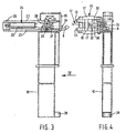
- the frame 8 to be coupled to a lifting device or the like conventionally comprises two upwardly extending, spaced-apart columns 10, one of which is shown in Figures 3 and 4.
- each column 10 Attached to the upper end of each column 10 is a first hook-shaped coupling means 9. Also attached to the upper end of each column 10 is a second coupling means 12, which is provided with two arms 13 positioned one above another, which arms are interconnected by a connecting piece 14.
- arms 13 form insert parts 15, which can be inserted, in a manner yet to be described in more detail hereafter, into coupling pieces 4 of containers placed one on top of another.
- said second coupling means 12 is pivotally connected by means of an upwardly or vertically extending pin 15' to one end of a more or less triangular, seen in top plan view, connecting piece 16.
- Said connecting piece 16 is built up of two plate-shaped part 17 disposed one above another, which are interconnected by a connecting piece 18 extending between said plate-shaped parts. It will be apparent in particular from Figure 4 that the end of the coupling piece 12 that is pivotally connected to connecting piece 16 by means of pin 15' is positioned between the ends of plate-shaped parts 17 of connecting piece 16.
- Connecting piece 16 is furthermore pivotally connected to frame 8, in particular to two vertically spaced-apart horizontal plates 20 and 21 mounted on the upper end of column 10, by means of a pin 19 extending parallel to pin 15'.
- a cylinder housing 25 of setting cylinder 24 is pivotally connected at its end remote from pin 22, by means of a pin 26 extending parallel to pin 22, to the ends of plates 20 and 21 remote from column 10, whereby, as is apparent in particular from Figure 3, the end of housing 25 of setting cylinder 24 that is connected by means of pin 26 is positioned between plates 20 and 21.
- such a connecting rod is built up of two plate-shaped parts 30 disposed one above another, which are interconnected at one end by means of a bush 32, in which pin 27 is accommodated, whilst the other ends are interconnected by means of a bush 33, in which pin 29 is accommodated.
- feeler pin 34 (Figure 3) is provided near the upper end of column 10, which pin is surrounded along part of its length by a compression spring 35, which attempts to retain the feeler pin 34 in the position which is shown in Figure 3.
- a compression spring 35 which attempts to retain the feeler pin 34 in the position which is shown in Figure 3.
- the free end of feeler pin 34 projects slightly from the supporting surface 36 present at the upper end of column 10, against which a container 1 coupled to the carrying device will abut, as will be explained in more detail hereafter.
- the feeler pin 34 which is likewise accommodated in the space between plates 20 and 21, includes a shoulder 37, which will activate a sensor means 38 upon moving to the left from the illustrated position, seen in Figure 3.
- a buffer 39 is disposed at the bottom end of each column 10, against which a container picked up by means of the carrying device will butt near its bottom side.
- the carrying device carried by a forklift truck or the like can be manipulated in such a manner that the free ends of insert parts of the hook-shaped coupling means 9 are inserted into coupling pieces present on the upper side of a container 1, as discussed above.
- the coupling pieces present near the upper side of the lower container will be positioned near the coupling pieces present on the bottom side of the upper container, whilst said coupling pieces need not always be positioned straight above each other thereby, as is indicated in Figure 6 for a coupling piece 4' on the upper side of a lower container and a coupling piece 4" on the bottom side of a container placed on top thereof.
- the upper insert parts 15 of the coupling means 12 will thereby be inserted into openings 7 of coupling pieces 4" of the upper container, which are present on the short sides of the container, whilst the lower insert parts 15 of the second coupling means 12 will be inserted into holes 7 in the respective coupling pieces 4', which are present on the sides of the lower container.
- the upper container will be moved with respect to the lower container if the upper container is not positioned straight above the lower container, and this in such a manner that eventually the coupling pieces 4' and 4" will be positioned straight above each other.
- each connecting rod 28 will have moved to a position in which it extends approximately perpendicularly to the boundary surface 2 of the container that faces towards the carrying device.
- pin 27, about which the coupling means 12 pivots with respect to connecting rod 28 is positioned on the side of connecting piece 16 remote from setting cylinder 24, it is furthermore possible to effect pivoting movement of coupling means 12 about pins 27 in the direction indicated by arrow A by means of setting cylinder 24, as is indicated in Figure 7, as a result of which coupling pieces 4', 4" will be pressed firmly against the supporting surfaces 36 of carrying frame 8 and be retained in this position.
- the feeler pins 34 disposed near the upper ends of the columns will be depressed and thus activate the sensor means. Said sensor means will then deliver a signal that the two containers are secured to carrying device 8 in the intended manner.
Landscapes
- Engineering & Computer Science (AREA)
- Transportation (AREA)
- Structural Engineering (AREA)
- Civil Engineering (AREA)
- Life Sciences & Earth Sciences (AREA)
- Geology (AREA)
- Mechanical Engineering (AREA)
- Forklifts And Lifting Vehicles (AREA)
- Stackable Containers (AREA)
Claims (6)
- Tragvorrichtung (8), die mit einem vertikal beweglichen Träger eines Gabelstaplers oder dergleichen zu koppeln ist, um zwei übereinander angeordnete Behälter (1) aufzuheben, die im Wesentlichen in der Nähe ihrer Eckpunkte mit Kopplungsteilen (4) versehen sind, in denen Öffnungen (5-7) vorhanden sind, wobei die Tragvorrichtung (8) einen Rahmen (8) und Einschubteile (9, 15) von mit dem Rahmen (8) der Tragvorrichtung verbundenen Kopplungsmitteln (9, 12) umfassen, wodurch die Einschubteile (9, 15) in die Öffnungen (5-7) der Kopplungsteile (4) des Behälters (1) eingeschoben werden können, wobei die Kopplungsmittel (9, 12) paarweise angeordnet sind, derart, dass ein Einschubteil eines ersten Kopplungsmittels (9) jedes Paars von Kopplungsmitteln (9, 12) in einer ersten Richtung in ein Kopplungsteil (9) eingeschoben werden kann, das in der Nähe der Oberseite des unteren der beiden übereinander angeordneten Behälter (1) vorgesehen ist, und zwei übereinander angeordnete Einschubteile (15) eines zweiten Kopplungsmittels (12) des fraglichen Paars, das in Bezug auf den Rahmen (8) der Tragvorrichtung eine Schwenkbewegung ausführen kann, in das Kopplungsteil (4') des ersten Behälters (1) und in ein an der Bodenseite des oberen Behälters (1) der übereinander angeordneten Behälter (1) vorgesehenes Kopplungsteil (4"), das in der Nähe des Kopplungsteils (4') des ersten Behälters (1) positioniert ist, in einer Richtung quer zu der Richtung, in der das Einschubteil des erste Kopplungsmittels (9) in das entsprechende Kopplungsteil (4') einzuschieben ist, eingeschoben werden können, wobei das zweite Kopplungsmittel (12) mit einem Ende mit einem Ende eines Verbindungsteils (16) schwenkbar (15') verbunden ist, dadurch gekennzeichnet, dass das Verbindungsteil (16) mit seinem anderen Ende mit dem Rahmen (8) der Tragvorrichtung schwenkbar (19) verbunden ist und ein Ende einer Verbindungsstange (28) mit dem zweiten Kopplungsmittel (12) zwischen den Enden des zweiten Kopplungsmittels (12) schwenkbar (27) verbunden ist, wobei das andere Ende der Verbindungsstange (28) mit dem Rahmen (8) der Tragvorrichtung schwenkbar (29) verbunden ist, während ein Antriebselement (24) zum Schwenken des zweiten Kopplungsmittels (12) mit dem Verbindungsteil (16) in Eingriff ist.
- Tragvorrichtung (8) nach Anspruch 1, dadurch gekennzeichnet, dass der Schwenkstift (19), um den das Verbindungsteil (16) in Bezug auf den Rahmen (8) schwenken kann, und der Schwenkstift (29), um den die Verbindungsstange (28) in Bezug auf den Rahmen (8) schwenken kann, in einer Ebene liegen, die sich zumindest im Wesentlichen parallel zu der Einschubrichtung des ersten Kopplungsmittels (7) erstreckt.
- Tragvorrichtung nach Anspruch 1 oder 2, dadurch gekennzeichnet, dass der Schwenkstift (19), um den das Verbindungsteil (16) in Bezug auf den Rahmen (8) schwenken kann, näher als der Schwenkstift (29), um den die Verbindungsstange (28) in Bezug auf den Rahmen (8) schwenken kann, bei jener Seite der Tragvorrichtung (18), die dem aufzuhebenden Behälter (1) zugewandt ist, angeordnet ist.
- Tragvorrichtung nach einem der vorhergehenden Ansprüche, dadurch gekennzeichnet, dass ein Stellzylinder (24) zwischen dem Rahmen (8) und dem Verbindungsteil (16) vorgesehen ist, wobei der Stellzylinder (24) mit dem Verbindungsteil (16) zwischen dem Verbindungspunkt (15') des zweiten Kopplungsmittels (12) mit dem Verbindungsteil (16) und dem Verbindungspunkt (19) des Verbindungsteils (16) mit dem Rahmen (8) in Eingriff ist.
- Tragvorrichtung nach einem der vorhergehenden Ansprüche, dadurch gekennzeichnet, dass die Konstruktion derart ist, dass in der Position des zweiten Kopplungsmittels (12), in der ein Behälter an der Tragvorrichtung (8) gesichert ist, der Schwenkstift (27) zwischen dem zweiten Kopplungsmittel (12) und der Kopplungsstange (28) auf der Seite des Verbindungsteils (16), die von dem Stellzylinder (24) wegweist, angeordnet ist, wodurch das Verbindungsteil (16) schwenken kann.
- Tragvorrichtung nach einem der vorhergehenden Ansprüche, dadurch gekennzeichnet, dass die Tragvorrichtung (8) mit einem Taststift (34) versehen ist, derart, dass der Taststift (34) bewegt wird, wenn ein Behälter (1) an dem Rahmen (8) gesichert wird.
Applications Claiming Priority (2)
| Application Number | Priority Date | Filing Date | Title |
|---|---|---|---|
| NL1010956A NL1010956C2 (nl) | 1999-01-05 | 1999-01-05 | Draaginrichting voor het opnemen van een tweetal boven elkaar geplaatste containers. |
| NL1010956 | 1999-01-05 |
Publications (2)
| Publication Number | Publication Date |
|---|---|
| EP1018481A1 EP1018481A1 (de) | 2000-07-12 |
| EP1018481B1 true EP1018481B1 (de) | 2006-04-05 |
Family
ID=19768417
Family Applications (1)
| Application Number | Title | Priority Date | Filing Date |
|---|---|---|---|
| EP99204615A Expired - Lifetime EP1018481B1 (de) | 1999-01-05 | 1999-12-29 | Tragvorrichtung zur Aufnahme von zwei aufeinander gestapelten Behältern |
Country Status (5)
| Country | Link |
|---|---|
| US (1) | US6431625B1 (de) |
| EP (1) | EP1018481B1 (de) |
| AT (1) | ATE322458T1 (de) |
| DE (1) | DE69930712D1 (de) |
| NL (1) | NL1010956C2 (de) |
Families Citing this family (4)
| Publication number | Priority date | Publication date | Assignee | Title |
|---|---|---|---|---|
| USD479029S1 (en) | 2002-04-08 | 2003-08-26 | Matthew R. Sobolewski | Hydraulic-powered telescopic forklift attachment |
| WO2009038399A2 (en) * | 2007-09-20 | 2009-03-26 | Posco | Appartus for controlling the position of crane tong according to slab bending and the method thereof |
| SE542417C2 (en) * | 2017-03-31 | 2020-04-28 | Elme Spreader Ab | Side lift spreader for lifting intermodal containers, and method of operating a side lift spreader |
| PL3601144T3 (pl) * | 2017-03-31 | 2022-01-17 | Elme Spreader Ab | Podnośnik boczny z rozsuwaną belką do transportu kontenerów intermodalnych |
Family Cites Families (10)
| Publication number | Priority date | Publication date | Assignee | Title |
|---|---|---|---|---|
| NL6808719A (de) * | 1967-07-15 | 1969-01-17 | ||
| US4546891A (en) * | 1983-02-24 | 1985-10-15 | Mi-Jack Products, Inc. | Grappler system for lifting apparatus |
| SE448985B (sv) * | 1984-01-04 | 1987-03-30 | Kalmar Last Maskin Verkstad Ab | Sidlyftsaggregat |
| US4824318A (en) * | 1984-04-04 | 1989-04-25 | Glenn Warner | Quick disconnect container carrier |
| NL8403553A (nl) * | 1984-11-22 | 1986-06-16 | Kuiken Nv | Container-hefraam voor heftruck. |
| NL193063C (nl) * | 1993-01-15 | 1998-09-08 | John Francis Heymans | Grijpinrichting voor laadkisten. |
| NL9301385A (nl) * | 1993-08-10 | 1995-03-01 | Mandigers Bv | Draaginrichting voor het opnemen van een tweetal boven elkaar geplaatste containers. |
| JPH09165200A (ja) * | 1995-12-18 | 1997-06-24 | Toyo Umpanki Co Ltd | コンテナ運搬用車両 |
| EP1005437A4 (de) * | 1996-02-21 | 2000-06-07 | Hyco Cascade Pty Ltd | Anordnung zum handhaben von kontainern |
| NL1004817C2 (nl) * | 1996-12-18 | 1998-06-19 | Smits Intellectual Property N | Draaginrichting voor het opnemen van een tweetal boven elkaar geplaatste containers. |
-
1999
- 1999-01-05 NL NL1010956A patent/NL1010956C2/nl not_active IP Right Cessation
- 1999-12-29 DE DE69930712T patent/DE69930712D1/de not_active Expired - Lifetime
- 1999-12-29 US US09/474,742 patent/US6431625B1/en not_active Expired - Fee Related
- 1999-12-29 EP EP99204615A patent/EP1018481B1/de not_active Expired - Lifetime
- 1999-12-29 AT AT99204615T patent/ATE322458T1/de not_active IP Right Cessation
Also Published As
| Publication number | Publication date |
|---|---|
| NL1010956C2 (nl) | 2000-07-06 |
| EP1018481A1 (de) | 2000-07-12 |
| DE69930712D1 (de) | 2006-05-18 |
| ATE322458T1 (de) | 2006-04-15 |
| US6431625B1 (en) | 2002-08-13 |
Similar Documents
| Publication | Publication Date | Title |
|---|---|---|
| US6533526B2 (en) | Fork lift rack displacement device | |
| EP0032449B1 (de) | Vorrichtung zum Handhaben von Lasten mit Klemmarmen für Hubwagen | |
| EP0007889B1 (de) | Palette | |
| US5042862A (en) | Gripping device | |
| US11858795B2 (en) | Pallet detection systems and methods for a material handling vehicle | |
| US6431625B1 (en) | Apparatus for picking up two containers placed one on top of another | |
| NL8402802A (nl) | Veelvoudige kantelinrichting voor een bak of een container gedragen door een voertuig. | |
| US4208160A (en) | Device for transferring load units | |
| WO2002049875A8 (fr) | Camionnette a cabine avancee et a plate-forme de transport de marchandises ou de personnes | |
| JPH06344963A (ja) | 車両シ−トの車両への搭載方法および車両シ−ト把持用ロボットハンド | |
| EP0638512A1 (de) | Tragvorrichtung zur Aufnahme von zwei aufeinander gestapelten Behältern | |
| US6086316A (en) | Container handling assembly | |
| JP2003063793A (ja) | フォークの接触検知センサ | |
| JPH07315785A (ja) | 鞘フォーク及びフォークリフト | |
| EP0892749B1 (de) | Gruppe aufgebaut aus mehreren tankbehältern die durch stangen miteinander verbunden sind sowie tankbehälter zur bildung einer solchen gruppe | |
| CN208843143U (zh) | 一种曲轴滑动支撑搬运组件 | |
| JPH0235759Y2 (de) | ||
| CN216917270U (zh) | 一种自动化立体仓库托盘 | |
| JP4737497B2 (ja) | パレットロック装置 | |
| KR100887969B1 (ko) | 차체 패널용 센터링 네스트 | |
| JPH05155599A (ja) | フォークリフトのリフトブラケット装置 | |
| JPS6136417Y2 (de) | ||
| JPH0659393U (ja) | 伸縮フォーク | |
| KR200141989Y1 (ko) | 물품 운반용 평판형 파렛트 | |
| JPS6239040Y2 (de) |
Legal Events
| Date | Code | Title | Description |
|---|---|---|---|
| PUAI | Public reference made under article 153(3) epc to a published international application that has entered the european phase |
Free format text: ORIGINAL CODE: 0009012 |
|
| AK | Designated contracting states |
Kind code of ref document: A1 Designated state(s): AT BE CH CY DE DK ES FI FR GB GR IE IT LI LU MC NL PT SE |
|
| AX | Request for extension of the european patent |
Free format text: AL;LT;LV;MK;RO;SI |
|
| 17P | Request for examination filed |
Effective date: 20010110 |
|
| AKX | Designation fees paid |
Free format text: AT BE CH CY DE DK ES FI FR GB GR IE IT LI LU MC NL PT SE |
|
| RAP1 | Party data changed (applicant data changed or rights of an application transferred) |
Owner name: GEBROEDERS G.P. EN TH.SMITS |
|
| 17Q | First examination report despatched |
Effective date: 20041228 |
|
| RAP1 | Party data changed (applicant data changed or rights of an application transferred) |
Owner name: VDL CONTAINERSYSTEMEN B.V. |
|
| GRAP | Despatch of communication of intention to grant a patent |
Free format text: ORIGINAL CODE: EPIDOSNIGR1 |
|
| GRAS | Grant fee paid |
Free format text: ORIGINAL CODE: EPIDOSNIGR3 |
|
| GRAA | (expected) grant |
Free format text: ORIGINAL CODE: 0009210 |
|
| AK | Designated contracting states |
Kind code of ref document: B1 Designated state(s): AT BE CH CY DE DK ES FI FR GB GR IE IT LI LU MC NL PT SE |
|
| PG25 | Lapsed in a contracting state [announced via postgrant information from national office to epo] |
Ref country code: NL Free format text: LAPSE BECAUSE OF FAILURE TO SUBMIT A TRANSLATION OF THE DESCRIPTION OR TO PAY THE FEE WITHIN THE PRESCRIBED TIME-LIMIT Effective date: 20060405 Ref country code: LI Free format text: LAPSE BECAUSE OF FAILURE TO SUBMIT A TRANSLATION OF THE DESCRIPTION OR TO PAY THE FEE WITHIN THE PRESCRIBED TIME-LIMIT Effective date: 20060405 Ref country code: IT Free format text: LAPSE BECAUSE OF FAILURE TO SUBMIT A TRANSLATION OF THE DESCRIPTION OR TO PAY THE FEE WITHIN THE PRESCRIBED TIME-LIMIT;WARNING: LAPSES OF ITALIAN PATENTS WITH EFFECTIVE DATE BEFORE 2007 MAY HAVE OCCURRED AT ANY TIME BEFORE 2007. THE CORRECT EFFECTIVE DATE MAY BE DIFFERENT FROM THE ONE RECORDED. Effective date: 20060405 Ref country code: FI Free format text: LAPSE BECAUSE OF FAILURE TO SUBMIT A TRANSLATION OF THE DESCRIPTION OR TO PAY THE FEE WITHIN THE PRESCRIBED TIME-LIMIT Effective date: 20060405 Ref country code: CH Free format text: LAPSE BECAUSE OF FAILURE TO SUBMIT A TRANSLATION OF THE DESCRIPTION OR TO PAY THE FEE WITHIN THE PRESCRIBED TIME-LIMIT Effective date: 20060405 Ref country code: BE Free format text: LAPSE BECAUSE OF FAILURE TO SUBMIT A TRANSLATION OF THE DESCRIPTION OR TO PAY THE FEE WITHIN THE PRESCRIBED TIME-LIMIT Effective date: 20060405 Ref country code: AT Free format text: LAPSE BECAUSE OF FAILURE TO SUBMIT A TRANSLATION OF THE DESCRIPTION OR TO PAY THE FEE WITHIN THE PRESCRIBED TIME-LIMIT Effective date: 20060405 |
|
| REG | Reference to a national code |
Ref country code: GB Ref legal event code: FG4D |
|
| REG | Reference to a national code |
Ref country code: CH Ref legal event code: EP |
|
| REG | Reference to a national code |
Ref country code: IE Ref legal event code: FG4D |
|
| REF | Corresponds to: |
Ref document number: 69930712 Country of ref document: DE Date of ref document: 20060518 Kind code of ref document: P |
|
| PG25 | Lapsed in a contracting state [announced via postgrant information from national office to epo] |
Ref country code: SE Free format text: LAPSE BECAUSE OF FAILURE TO SUBMIT A TRANSLATION OF THE DESCRIPTION OR TO PAY THE FEE WITHIN THE PRESCRIBED TIME-LIMIT Effective date: 20060705 Ref country code: DK Free format text: LAPSE BECAUSE OF FAILURE TO SUBMIT A TRANSLATION OF THE DESCRIPTION OR TO PAY THE FEE WITHIN THE PRESCRIBED TIME-LIMIT Effective date: 20060705 |
|
| PG25 | Lapsed in a contracting state [announced via postgrant information from national office to epo] |
Ref country code: DE Free format text: LAPSE BECAUSE OF FAILURE TO SUBMIT A TRANSLATION OF THE DESCRIPTION OR TO PAY THE FEE WITHIN THE PRESCRIBED TIME-LIMIT Effective date: 20060706 |
|
| PG25 | Lapsed in a contracting state [announced via postgrant information from national office to epo] |
Ref country code: ES Free format text: LAPSE BECAUSE OF FAILURE TO SUBMIT A TRANSLATION OF THE DESCRIPTION OR TO PAY THE FEE WITHIN THE PRESCRIBED TIME-LIMIT Effective date: 20060716 |
|
| PG25 | Lapsed in a contracting state [announced via postgrant information from national office to epo] |
Ref country code: PT Free format text: LAPSE BECAUSE OF FAILURE TO SUBMIT A TRANSLATION OF THE DESCRIPTION OR TO PAY THE FEE WITHIN THE PRESCRIBED TIME-LIMIT Effective date: 20060905 |
|
| NLV1 | Nl: lapsed or annulled due to failure to fulfill the requirements of art. 29p and 29m of the patents act | ||
| REG | Reference to a national code |
Ref country code: CH Ref legal event code: PL |
|
| PG25 | Lapsed in a contracting state [announced via postgrant information from national office to epo] |
Ref country code: IE Free format text: LAPSE BECAUSE OF NON-PAYMENT OF DUE FEES Effective date: 20061229 |
|
| PG25 | Lapsed in a contracting state [announced via postgrant information from national office to epo] |
Ref country code: MC Free format text: LAPSE BECAUSE OF NON-PAYMENT OF DUE FEES Effective date: 20061231 |
|
| PLBE | No opposition filed within time limit |
Free format text: ORIGINAL CODE: 0009261 |
|
| STAA | Information on the status of an ep patent application or granted ep patent |
Free format text: STATUS: NO OPPOSITION FILED WITHIN TIME LIMIT |
|
| EN | Fr: translation not filed | ||
| 26N | No opposition filed |
Effective date: 20070108 |
|
| GBPC | Gb: european patent ceased through non-payment of renewal fee |
Effective date: 20061229 |
|
| PG25 | Lapsed in a contracting state [announced via postgrant information from national office to epo] |
Ref country code: GB Free format text: LAPSE BECAUSE OF NON-PAYMENT OF DUE FEES Effective date: 20061229 |
|
| PG25 | Lapsed in a contracting state [announced via postgrant information from national office to epo] |
Ref country code: GR Free format text: LAPSE BECAUSE OF FAILURE TO SUBMIT A TRANSLATION OF THE DESCRIPTION OR TO PAY THE FEE WITHIN THE PRESCRIBED TIME-LIMIT Effective date: 20060706 Ref country code: FR Free format text: LAPSE BECAUSE OF FAILURE TO SUBMIT A TRANSLATION OF THE DESCRIPTION OR TO PAY THE FEE WITHIN THE PRESCRIBED TIME-LIMIT Effective date: 20070309 |
|
| PG25 | Lapsed in a contracting state [announced via postgrant information from national office to epo] |
Ref country code: LU Free format text: LAPSE BECAUSE OF NON-PAYMENT OF DUE FEES Effective date: 20061229 |
|
| PG25 | Lapsed in a contracting state [announced via postgrant information from national office to epo] |
Ref country code: FR Free format text: LAPSE BECAUSE OF FAILURE TO SUBMIT A TRANSLATION OF THE DESCRIPTION OR TO PAY THE FEE WITHIN THE PRESCRIBED TIME-LIMIT Effective date: 20060405 Ref country code: CY Free format text: LAPSE BECAUSE OF FAILURE TO SUBMIT A TRANSLATION OF THE DESCRIPTION OR TO PAY THE FEE WITHIN THE PRESCRIBED TIME-LIMIT Effective date: 20060405 |