EP1016848B1 - Plattenwärmetauscher - Google Patents
Plattenwärmetauscher Download PDFInfo
- Publication number
- EP1016848B1 EP1016848B1 EP99125616A EP99125616A EP1016848B1 EP 1016848 B1 EP1016848 B1 EP 1016848B1 EP 99125616 A EP99125616 A EP 99125616A EP 99125616 A EP99125616 A EP 99125616A EP 1016848 B1 EP1016848 B1 EP 1016848B1
- Authority
- EP
- European Patent Office
- Prior art keywords
- plates
- plate
- orientation
- face
- heat exchanger
- Prior art date
- Legal status (The legal status is an assumption and is not a legal conclusion. Google has not performed a legal analysis and makes no representation as to the accuracy of the status listed.)
- Expired - Lifetime
Links
Images


Classifications
-
- F—MECHANICAL ENGINEERING; LIGHTING; HEATING; WEAPONS; BLASTING
- F28—HEAT EXCHANGE IN GENERAL
- F28D—HEAT-EXCHANGE APPARATUS, NOT PROVIDED FOR IN ANOTHER SUBCLASS, IN WHICH THE HEAT-EXCHANGE MEDIA DO NOT COME INTO DIRECT CONTACT
- F28D1/00—Heat-exchange apparatus having stationary conduit assemblies for one heat-exchange medium only, the media being in contact with different sides of the conduit wall, in which the other heat-exchange medium is a large body of fluid, e.g. domestic or motor car radiators
- F28D1/02—Heat-exchange apparatus having stationary conduit assemblies for one heat-exchange medium only, the media being in contact with different sides of the conduit wall, in which the other heat-exchange medium is a large body of fluid, e.g. domestic or motor car radiators with heat-exchange conduits immersed in the body of fluid
- F28D1/03—Heat-exchange apparatus having stationary conduit assemblies for one heat-exchange medium only, the media being in contact with different sides of the conduit wall, in which the other heat-exchange medium is a large body of fluid, e.g. domestic or motor car radiators with heat-exchange conduits immersed in the body of fluid with plate-like or laminated conduits
- F28D1/0308—Heat-exchange apparatus having stationary conduit assemblies for one heat-exchange medium only, the media being in contact with different sides of the conduit wall, in which the other heat-exchange medium is a large body of fluid, e.g. domestic or motor car radiators with heat-exchange conduits immersed in the body of fluid with plate-like or laminated conduits the conduits being formed by paired plates touching each other
- F28D1/0325—Heat-exchange apparatus having stationary conduit assemblies for one heat-exchange medium only, the media being in contact with different sides of the conduit wall, in which the other heat-exchange medium is a large body of fluid, e.g. domestic or motor car radiators with heat-exchange conduits immersed in the body of fluid with plate-like or laminated conduits the conduits being formed by paired plates touching each other the plates having lateral openings therein for circulation of the heat-exchange medium from one conduit to another
- F28D1/0333—Heat-exchange apparatus having stationary conduit assemblies for one heat-exchange medium only, the media being in contact with different sides of the conduit wall, in which the other heat-exchange medium is a large body of fluid, e.g. domestic or motor car radiators with heat-exchange conduits immersed in the body of fluid with plate-like or laminated conduits the conduits being formed by paired plates touching each other the plates having lateral openings therein for circulation of the heat-exchange medium from one conduit to another the plates having integrated connecting members
-
- F—MECHANICAL ENGINEERING; LIGHTING; HEATING; WEAPONS; BLASTING
- F28—HEAT EXCHANGE IN GENERAL
- F28F—DETAILS OF HEAT-EXCHANGE AND HEAT-TRANSFER APPARATUS, OF GENERAL APPLICATION
- F28F9/00—Casings; Header boxes; Auxiliary supports for elements; Auxiliary members within casings
- F28F9/02—Header boxes; End plates
- F28F9/0202—Header boxes having their inner space divided by partitions
- F28F9/0204—Header boxes having their inner space divided by partitions for elongated header box, e.g. with transversal and longitudinal partitions
- F28F9/0214—Header boxes having their inner space divided by partitions for elongated header box, e.g. with transversal and longitudinal partitions having only longitudinal partitions
-
- Y—GENERAL TAGGING OF NEW TECHNOLOGICAL DEVELOPMENTS; GENERAL TAGGING OF CROSS-SECTIONAL TECHNOLOGIES SPANNING OVER SEVERAL SECTIONS OF THE IPC; TECHNICAL SUBJECTS COVERED BY FORMER USPC CROSS-REFERENCE ART COLLECTIONS [XRACs] AND DIGESTS
- Y10—TECHNICAL SUBJECTS COVERED BY FORMER USPC
- Y10S—TECHNICAL SUBJECTS COVERED BY FORMER USPC CROSS-REFERENCE ART COLLECTIONS [XRACs] AND DIGESTS
- Y10S165/00—Heat exchange
- Y10S165/906—Reinforcement
Definitions
- the subject of the present invention is a heating device, ventilation and / or air conditioning with a thermal loop fitted with a evaporator, said evaporator consisting of a stack of plates having first and second opposite longitudinal ends, some of which have separating elements intended to divert a flow of refrigerant flowing in an axial direction of the evaporator to direct it towards a region of channel in which it travels from one said end to the other in one direction longitudinal of the plates.
- WO 99/13282 presents such a exchanger.
- the partition plates and, more generally, the passages of boxes in brazed plate evaporators are designed to meet the mechanical strength requirements and to promote a balanced distribution of the fluid refrigerant on different channels.
- the parts of the refrigerant conduits near the inlet and outlet manifolds meet the same requirements, while also seeking to favor the turbulence of the flow to intensify the heat exchanges.
- the geometry is a source of turbulence and refrigerant stalls that are likely to generate an acoustic emission disturbing the comfort of the user.
- the present invention proposes to reduce the flow noise which is generated outside by the evaporator.
- the invention proposes to limit the vibrational excitation of partition plates or end plates.
- the basic idea of the invention is to limit excitations in the areas where the refrigerant arrives on the walls of the exchanger with a speed component perpendicular to the wall, this being obtained by adding stiffening elements which limit the response of the wall to frontal impact of the fluid.
- the invention thus relates to a device for heating, ventilation and / or air conditioning with a fitted thermal loop a heat exchanger, for example an evaporator, said heat exchanger consisting of a stack of orientation plates having a first and second ends called longitudinal opposite, and having plates end arranged at two opposite axial ends of the heat exchanger, certain orientation plates with dividing elements intended to derive a flow of refrigerant flowing in a so-called axial direction of the heat exchanger heat to direct it to a channel region in which it travels with a so-called end to end in a so-called longitudinal direction of the orientation plates, characterized in that at least one separating element has at least one means stiffening which is secured by stamping or by molding to at least one area of said separating element. This makes it possible to reduce the vibration amplitudes and / or to guide the fluid.
- Heat exchangers generally have a shape rectangular whose largest dimension is parallel to the direction of flow not derived from the refrigerant.
- Orientation plates are generally rectangular and have a length which is parallel to the direction of flow of the fluid in the canals.
- the invention also applies to other geometries.
- axial extends as designating the direction of refrigerant flow when it is not bypassed by a plate of orientation and the term “longitudinal direction of the orientation plates” means as the general direction of fluid flow along the channel (s), longitudinal end to the other of the plates.
- orientation plates are partition plates which have at least one end at least one separating wall constituting a said separating element and which has at least one rib which constitutes a said stiffening means.
- At least certain plates orientation are so-called standard plates presenting at their first and second ends at least one boss provided with an opening allowing an axial passage refrigerant and at least some orientation plates are substantially flat and have at least one end at least one separating wall whose the thickness is greater than twice the thickness of a so-called standard plate, this thickness advantageously being at least equal to the thickness of an end plate, and which constitutes a said stiffening means.
- the plate may have a thickness substantially constant or even the separating wall may have a thickness greater than that of the rest of the plate. It is particularly advantageous the separating wall is profiled so as to guide the refrigerant from said axial direction of the evaporator towards said longitudinal direction of the plates, which reduces noise by at least partially avoiding the impact due to said noise speed component.
- the heat exchanger for example an evaporator, consists of a stack of so-called standard plates and partition plates having at their first and at their second ends at least one boss having a face support, at least one of which has a separating element and at least one plate plane is interposed between the bearing faces of the bosses of two partition plates.
- the evaporator is constituted by a stack of said standard plates, which have a first face, in particular planar, and a second face in particular plane from which extend said bosses, and at least some said flat plates are interposed between the first faces of two plates standards so as to define two half-channels for refrigerant passage, one between the first face of one of said two standard plates and a first face of said flat plate and the other between the second face of said flat plate and the first face of the other of said two standard plates.
- At least one said flat plate may have at one end at minus an opening for the axial passage of refrigerant.
- a said stiffening means is a stiffening plate interposed between a said end of two plates and which is integral with these.
- this stiffening means is a stiffening plate secured to one end of said end plate.
- said stiffening means is constituted by an edge of the end plate which is folded over one face of said end plate.
- at least one transverse edge and / or one edge longitudinal protruding from the end plate can be folded against at least a side surface of the heat exchanger.
- the invention aims to reduce the noise generated by the end plates by decoupling them from mechanical stresses that they receive.
- the invention relates to a device for heating, ventilation and / or air conditioning with a fitted thermal loop a heat exchanger, for example an evaporator, said heat exchanger consisting of a stack of orientation plates having a first and second opposite longitudinal ends defining regions therebetween in which a refrigerant flows from one said end to the other in a longitudinal direction of the orientation plates, the first and the second longitudinal ends of the orientation plates having means for directing a flow of the refrigerant, either in an axial direction of the evaporator, or, in the drift, in a longitudinal direction of the orientation plates in a so-called channel region, some orientation plates being axial orientation plates, and some orientation plates being partition plates which, at least one of their ends, derive said fluid flow, in a said channel region, the heat exchanger, also having end plates arranged in two opposite axial ends of the evaporator, characterized in that at least one of the first and second longitudinal ends of at least one partition plate and / or at least one end plate is respectively coupled to
- This element shock absorber may be a stamped boss secured to the corresponding end of the end plate.
- This damping element can also be a metal sheet corrugated.
- At least one damping element is advantageously secured to a means stiffening, so as to combine the damping effect and the stiffening effect, by example that provided by a ribbed separating wall.
- the invention aims to reduce the noise generated by the end plates by reducing the acoustic coupling thereof with the outside of the heat exchanger, for example an evaporator.
- the plates are generally brazed around a contour and have free regions protruding from the outside or inside of this outline and which are not attached to the rest of the evaporator.
- these protruding regions are requested by the vibrations thus produced and also start to vibrate, which induces a coupling acoustics with the outside which is all the more important as the surface concerned is itself important.
- the basic idea of the invention in its third concept is to reduce or even eliminate the influence of these protruding regions which are not attached to the evaporator.
- the invention relates to a heating device, ventilation and / or air conditioning with a thermal loop fitted with a evaporator, said evaporator consisting of a stack of orientation plates having first and second opposite longitudinal ends and defining between them channel regions in which a refrigerant runs from one end to the other in a longitudinal region of the plates, the first and second longitudinal ends of the orientation plates having means for directing a flow of refrigerant, either in an axial direction at the evaporator, either in a longitudinal direction of the plates in a said region of channel, the evaporator having end plates arranged at two ends opposite axial sides of the evaporator and at least part of which, in particular the contour is secured, in particular by brazing, to an orientation plate, characterized in that that at least one edge of said part, in particular of the contour, is free from a region not secured to the orientation plate.
- At least one outer edge of said part of the outline is bordered by a folded edge secured to said orientation plate.
- at least one edge of said part of the contour constitutes an edge of an opening in an end plate. The surface of said opening is advantageously equal to 20% of the total surface of the plate end.
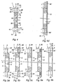
- an orientation plate 1 called standard plate has at each of its longitudinal ends a pair of bosses 15, of which each has an opening 16 allowing the passage of a refrigerant in an axial direction of the evaporator.
- These stamped bosses 15, which are directed towards the rear of Figure 1, are connected by hollow channels 14 delimited laterally by a longitudinal edge 11 of the plate 1 and separated from each other by a rib central longitudinal stamped 17.
- the face 18 (which is seen in Figure 1) carries the channels 14 above while the opposite face 19 which is substantially planar in its central region is bordered at its ends by protruding bosses 15, as the better shows Figure 3a.
- Figure 2a shows an orientation plate which constitutes a partition plate 20 and which is distinguished from plate 1 by the presence of at least one longitudinal ends of a separating wall 26 which constitutes the bottom of a embossed boss 25 and which prevents the axial passage of the refrigerant and which requires to redirect in a longitudinal direction of the plate in regions of channels 24.
- a heat exchanger such as an evaporator is consisting of a stack of orientation plates, some of which are plates of axial orientation (or standard plates) and some of which are plates of partition which derive at least one of their ends the axial flow of the liquid refrigerant to supply the channels.
- the axial ends of the evaporator are fitted with end plates.
- ribs 26 ' which come from stamping with the partition plate 20 (or which are molded in plastic when the evaporator plates are plastic).
- a partition plate will be referenced 2 if it has a non-ribbed separating wall 26, in accordance with the prior art. If she has a separating wall 26 provided with ribs 26 ′, it will be referenced 20.
- Figure 2b shows a stack of so-called orientation plates standard 1 and partition plates 20.
- This stacking of plates is made of manner known per se and defines, on the one hand, two supply channels 3 and 3 'located at the longitudinal ends of the plates and oriented in an axial direction of the evaporator (arrow F) and, on the other hand, channel regions 4 oriented in a longitudinal direction of the plates (arrow F ') between a face 18 of a plate 1 and a face 28 of a plate 2, that is to say that each longitudinal channel 4 of the plates is composed of two half-channels facing each other 14 and 28.
- the bosses 15 and 25 are mounted head to tail and between them is trapped a corrugated sheet 5 generally called "fins" which is used conventionally to activate the heat exchanges of the evaporator.
- the bosses 25 of the plates 20 have dividing walls 26 provided with ribs 26 '.
- the ribs 26 ' shown in Figure 2a, have the form of braces, this shape is only given by way of example any shape stamped on the bottom 26 of the bosses 25 can perform the same function.
- the face 29 of a first partition plate 20 is assembled against the face 19 of a second partition plate 20 so that the recess formed by the rib 26 'of the first partition plate is in communication with the recess formed by the rib 26 'of the second partition plate.
- the change of direction of the flow is carried out using two partition plates.
- the face 29 of the partition plate 20 having ribs 26 ' is interposed between the face 19 a standard orientation plate 1 and the face 18 of another orientation plate standard 1.
- the change in direction of the flow is produced using a single partition plate 20.
- Another way to reduce noise is to interpose plates thicker or with extra thickness at the closed end.
- Figure 3a shows an embodiment of the invention in which the evaporator has so-called standard plates 1 stacked alternately in one direction and in the other, that is to say that the bosses 15 are located alternately on the left and right side of the plate.
- Fins 51 and 52 are arranged between the faces 19 of two adjacent plates 1 whose bosses 15 are made face by aligning their openings 16.
- Between the faces 18 of adjacent plates 1 are arranged one or more thick partition plates 6 which are substantially planes, which are closed at one of their longitudinal ends 60, and which have an opening 61 at their other end.
- These plates 6 are thick plates which have a thickness e at least twice the thickness (some tenths of mm) of the sheet metal constituting the plates 1 and which is advantageously greater than the thickness e 'of an end plate, which is approximately 1 mm.
- the plates 6 are inserted between two adjacent orientation plates, then brazed to them.
- the assembly defines two half-channels 7 and 7 ′ separated at the level of the axial channel 3 and which communicate with each other by the opening 61, at the axial channel 3 '.
- plates 1 and 2 are stacked as shown and a thick flat plate 65 closed to a longitudinal end and open by an opening 66 at its other end longitudinal is brazed between the bosses 25 of two partition plates 2 (or 20).
- This thick plate 65 constitutes a stiffening element which reduces the emission acoustic due to the impact on the bottom 26 of the refrigerant coming from channel 3 in the direction of arrow F.
- a corrugated metal sheet 53 is arranged between a side 29 of a plate 2 and one side of the plate 65 and another metal sheet corrugated 54 is arranged between the other face of the sheet 65 and the face 29 of the plate 2.
- Figure 3c shows an embodiment which differs from the Figure 3a by the fact that the plate 6 has an extra thickness 67 at its end longitudinal at the axial channel 3.
- the extra thickness 67 has a convex profile 68, which is able to facilitate the redirection of the axial flow towards the channels 7 and 7 ', preventing the fluid from attacking the plate 6 perpendicularly.
- this extra thickness 67 advantageously has a concave profile so as to channel and to guide the fluid towards the channel 7.
- Figure 4 shows a stack of plates 1 and 2 which is performed in the same way as in the case of Figure 3c, but in which the plate 65 is replaced by a thick plate 70 which extends across the width of the end corresponding longitudinal.
- the bosses 25 of the plates 2 present at this end a lower height than at the other end, so as to take into account the thickness of this plate 70 (for example 1 mm or more).
- the plate 6, the extra thickness 67 as well as the plate 70 are molded either from metal such as steel or aluminum or from a flexible material such as polymer or rubber.
- Figure 5a shows the end of an evaporator according to the art prior.
- An end plate 9 having recesses 91 at each of these longitudinal ends which are extended by planar regions 92 which are brazed on the bosses 25 of partition plates 2, a corrugated metal sheet 5 being trapped between the end plate 9 and the face 29 of the plate 2, for the fields between the evaporator and its environment.
- a plate 93 is brazed on the external faces 98 of the flat regions 92 to constitute a stiffening element capable of reducing the noise generated by the axial impact of the fluid on the solid faces 26 of the plate (or 20).
- the end plate 9 is flat and the thick end plates 90 'are arranged between them and the bosses 25 partition plate 2 (or 20).
- Figure 5d also not in accordance with the invention, differs from Figure 5c by the fact that the end plates 90 are replaced by larger 90 'plates thickness, while the bosses 25 are replaced by bosses 24 of lower height, while keeping the same space available for the sheet corrugated metal 5.
- transverse ends 96 and / or longitudinal 97 protruding from the end plate 9 are folded and brazed along the masses additional and / or fins.
- Figure 6a illustrates a second concept according to the invention.
- a flat end plate 9 is brazed on fins 5 having, at each of their longitudinal end, a region of height h which extends over a length corresponding approximately to the transverse dimension of the bosses 25 and, in part central, a region of height H which extends over a length corresponding approximately to the length of the channels 4. This allows a decoupling by damping between the plate 9 and the bosses 25 of the orientation plate 2 (or 20).
- the plate 9 is decoupled by bosses 95 which dampen the transmission of vibrations from the plate orientation 2 (or 20).
- the bosses 95 may consist of an orientation plate 1, 2 or 20 which is interposed between a partition plate 2 (or 20) and the plate end 9, the plate 9 being brazed against the face 28 of the orientation plate 1, 2 or 20.
- the bosses 25 of the partition plate are brazed against the bosses 25 of the orientation plate 1, 2 or 20.
- the planar end regions 92 in which the end plate 9 is brazed on the partition plate 2 have protruding parts or flanges 96 which project outwards beyond of the boss 25 of the partition plate 2.
- this rim 96 is eliminated so that the plate 9 has edges 99 which do not do not extend beyond the contours on which the plate 9 is secured to the bosses 25, or preferably, as shown in Figure 7c, it is folded over the face 98 of the planar region 92.
- the end plate 9 also shown in the Figure 8a may also have overhanging longitudinal regions 97 which are according to the invention advantageously folded and brazed on a lateral face of the evaporator.
- the central region of the end plate 9, which is not secured to the evaporator, is capable of constituting an acoustic coupling region of large area. According to the invention, it is proposed to eliminate it by providing a cutout 108 of rectangular outline 100, 101. According to another embodiment, the end plate 9, shown in Figure 8b, has a central cutout 108 and its transverse 96 and longitudinal 97 protruding ends have been eliminated.
- the end plate 9 which is shown for example in Figure 8c, no longer has regions that are not joined together nor towards the outside, since the regions protruding 96 and 97 were folded and brazed on the bosses 25 of the plate partition 2, nor inward since the cutout 108 has been made. Note that if the embodiment of Figure 8c provides for a folding and brazing of the protruding region 96 on the boss 25, it is also possible to perform these drawdowns on plate 9, as in Figure 7c.
- the cut surface 108 represents more than 20% of the surface of a face of an orientation plate (or of an end plate classic).
- it remove as much material as possible from the plate.
- the remaining part of the plate protects the fins during the brazing process.
- the remaining part of the plate shown in Figure 8b, has the shape of a frame, however this shape is not in no way limiting, the remaining part being able to be thumped by one or more intersecting bands (as shown in dotted lines at 120 in Figure 8b). These strips are joined at 121, for example up to their edges 122, to a plate orientation.
Landscapes
- Engineering & Computer Science (AREA)
- Physics & Mathematics (AREA)
- Thermal Sciences (AREA)
- Mechanical Engineering (AREA)
- General Engineering & Computer Science (AREA)
- Heat-Exchange Devices With Radiators And Conduit Assemblies (AREA)
- Details Of Heat-Exchange And Heat-Transfer (AREA)
- Air-Conditioning For Vehicles (AREA)
Claims (14)
- Heiz-, Belüftungs- und/oder Klimaanlage, umfassend einen thermischen Kreis, der mit einem Wärmetauscher ausgestattet ist, wobei der Wärmetauscher gebildet ist aus einer Stapelung an Ausrichtungsplatten, erste und zweite gegenüberstehende Längsenden aufweisend und aufweisend Endplatten (9), angeordnet an zwei axial gegenüberstehenden Enden des Wärmetauschers, wobei einige der Ausrichtungsplatten Trennelemente aufweisen, bestimmt zur Umlenkung oder Umleitung einer Kältemittelfluidströmung, in einer axialen Richtung des Wärmetauschers strömend, um sie hin zu einem Kanalbereich zu richten, in welchem sie von einem Ende zum anderen in der Längsrichtung der Ausrichtungsplatten tritt, dadurch gekennzeichnet, dass zumindest ein Trennelement (6, 26) zumindest ein Versteifungsmittel (26', 65, 67, 70) umfaßt, verbunden durch Prägen bzw. Tiefziehen oder Kümpeln oder durch Formen bzw. Gießen bzw. Angießen mit zumindest einer Zone des Trennelementes (6, 26).
- Anlage nach Anspruch 1, dadurch gekennzeichnet, dass zumindest bestimmte der Ausrichtungsplatten Partitionierplatten (20) sind, die an zumindest einem Ende eine Trennwandung (26) aufweisen, ein Trennelement ausbildend, und zumindest eine Rippe (26') aufweisend, die ein Versteifungs- oder Verstärkungsmittel ausbildet.
- Anlage nach Anspruch 1, dadurch gekennzeichnet, dass zumindest bestimmte oder einige Ausrichtungplatten sogenannte Standard- oder Normplatten (1) sind, aufweisend an den ersten und zweiten Ende zumindest einen Höcker (15), bereitgestellt mit einer Öffnung (16), die einen axialen Durchtritt des Kältemittelfluids ermöglicht, und dass zumindest einige oder bestimmte Ausrichtungsplatten (6) im wesentlichen planar sind und an zumindest einem Ende zumindest eine Trennwandung aufweisen, deren Dicke größer ist als die zweifache Dicke einer Standard- bzw. Normplatte (1), insbesondere zumindest gleich zur Dicke einer Endplatte (9), wobei diese Trennwandung ein Versteifungsmittel bildet.
- Anlage nach Anspruch 3, dadurch gekennzeichnet, dass eine Ausrichtungsplatte (6) eine im wesentlichen konstante Dicke (e) aufweist.
- Anlage nach Anspruch 3, dadurch gekennzeichnet, dass die Trennwandung (67) eine Dikke aufweist, die größer ist als jene (e) des Restes der Platte oder Plakette (6).
- Anlage nach Anspruch 5, dadurch gekennzeichnet, dass die Trennwandung (67) profiliert ist bzw. Profile (68) aufweist, zum Zwecke der Führung des Kältemittelfluids, ausgehend von der axialen Richtung (F) des Verdampfers hin zu der Längsrichtung (F') der Ausrichtungsplatten (1, 2).
- Anlage nach einem der Ansprüche 3 bis 6, dadurch gekennzeichnet, dass der Verdampfer gebildet ist durch eine Stapelung an Standard- oder Normplatten (1), aufweisend eine erste Fläche (18) und eine zweite Fläche (19), ausgehend von welcher sich die Höcker (15) erstrecken, und dass zumindest einige oder bestimmte der Ebenen oder planaren Platten (6) zwischengelagert oder eingeklemmt sind zwischen den ersten Flächen (18) von zwei Standard- oder Normplatten (1), so dass zwei Halbkanäle (7, 7') für den Durchtritt des Kältemittelfluids definiert sind, einer zwischen der ersten Fläche (18), einer der zwei Standard- oder Normplatten (1) und einer ersten Fläche der ebenen oder planaren Platte (6), sowie ein anderer zwischen der zweiten Fläche der ebenen oder planaren Platte (6) und der ersten Fläche (18) der anderen der zwei Standard- oder Normplatten (1).
- Anlage nach einem der Ansprüche 1 oder 2, dadurch gekennzeichnet, dass der Wärmetauscher gebildet ist durch eine Stapelung an Standard- oder Normplatten (1) und an Partitionierplatten (2, 20), aufweisend an den ersten und zweiten Enden zumindest einen Höcker (25), eine Anlagefläche (25') aufweisend, wobei zumindest ein Trennelement (26) daran vorgesehen ist, und dass zumindest eine ebene oder planare Platte (65) zwischengelagert oder eingeklemmt ist zwischen den Anlageflächen (25') von Höckern (25) von zwei Trenn- oder Partitionierplatten (2, 20).
- Anlage nach den Ansprüchen 3 bis 8, dadurch gekennzeichnet, dass zumindest eine ebene oder planare Platte (6) an einem Ende zumindest eine Öffnung (61, 66) für den axialen Durchtritt des Kältemittelfluids aufweist.
- Anlage nach Anspruch 1, dadurch gekennzeichnet, dass ein Versteifungs- oder Verstärkungsmittel eine Versteifungs- oder Verstärkungsplatte (70) ist, zwischengelagert zwischen einem Ende von zwei Ausrichtungsplatten (2, 20), wobei eine diesbezügliche Verbindung vorgesehen ist.
- Anlage nach Anspruch 1, dadurch gekennzeichnet, dass sie zumindest eine Endplatte (9) umfaßt, die zumindest ein Versteifungs- oder Verstärkungsmittel umfaßt.
- Anlage nach Anspruch 11, dadurch gekennzeichnet, dass das Verstärkungs- oder Versteifungsmittel eine Versteifungs- oder Verstärkungsplatte (90, 90', 93) ist, verbunden mit einem Ende der Endplatte (9).
- Anlage nach Anspruch 11, dadurch gekennzeichnet, dass das Versteifungs- oder Verstärkungsmittel gebildet ist durch einen Rand (96) der Endplatte (9), zurückgefaltet bzw. zurückgeschlagen an einer Fläche (98) der Endplatte (9).
- Anlage nach Anspruch 11, dadurch gekennzeichnet, dass zumindest ein transversaler Rand (96) und/oder ein Längsrand (97) der Endplatte (9) zurückgeschlagen oder umgefaltet ist gegen zumindest eine Lateralfläche des Wärmetauschers.
Applications Claiming Priority (2)
| Application Number | Priority Date | Filing Date | Title |
|---|---|---|---|
| FR9816635 | 1998-12-30 | ||
| FR9816635A FR2788116B1 (fr) | 1998-12-30 | 1998-12-30 | Dispositif de chauffage, ventilation et/ou climatisation comportant une boucle thermique equipee d'un evaporateur |
Publications (2)
| Publication Number | Publication Date |
|---|---|
| EP1016848A1 EP1016848A1 (de) | 2000-07-05 |
| EP1016848B1 true EP1016848B1 (de) | 2003-03-12 |
Family
ID=9534679
Family Applications (1)
| Application Number | Title | Priority Date | Filing Date |
|---|---|---|---|
| EP99125616A Expired - Lifetime EP1016848B1 (de) | 1998-12-30 | 1999-12-22 | Plattenwärmetauscher |
Country Status (6)
| Country | Link |
|---|---|
| US (1) | US6408940B1 (de) |
| EP (1) | EP1016848B1 (de) |
| JP (1) | JP4809512B2 (de) |
| DE (1) | DE69905848T2 (de) |
| ES (1) | ES2194416T3 (de) |
| FR (1) | FR2788116B1 (de) |
Families Citing this family (7)
| Publication number | Priority date | Publication date | Assignee | Title |
|---|---|---|---|---|
| US6427764B2 (en) * | 1996-02-01 | 2002-08-06 | Ingersoll-Rand Energy Systems Corporation | Heat exchanger having selectively compliant end sheet |
| US20070144715A1 (en) * | 2003-12-09 | 2007-06-28 | Showa Denko K.K. | Evaporator |
| JP4426328B2 (ja) * | 2004-02-06 | 2010-03-03 | サンデン株式会社 | 積層型熱交換器 |
| US7753105B2 (en) * | 2006-05-16 | 2010-07-13 | Delphi Technologies, Inc. | Liquid cooled condenser having an integrated heat exchanger |
| FR3081383B1 (fr) * | 2018-05-22 | 2023-10-20 | Valeo Systemes Thermiques | Dispositif de ventilation d’un vehicule automobile |
| US11633799B2 (en) * | 2020-10-01 | 2023-04-25 | Hamilton Sundstrand Corporation | Control assembly fabrication via brazing |
| KR102942940B1 (ko) * | 2023-02-20 | 2026-03-23 | 엘지전자 주식회사 | 열교환기 |
Family Cites Families (22)
| Publication number | Priority date | Publication date | Assignee | Title |
|---|---|---|---|---|
| US4274482A (en) * | 1978-08-21 | 1981-06-23 | Nihon Radiator Co., Ltd. | Laminated evaporator |
| JPS58162475U (ja) * | 1982-04-24 | 1983-10-28 | 株式会社ボッシュオートモーティブ システム | 積層型の蒸発器 |
| JPS6039960B2 (ja) * | 1982-09-01 | 1985-09-09 | 株式会社日阪製作所 | シエルアンドプレ−ト式熱交換器 |
| JPS6082170U (ja) * | 1983-11-14 | 1985-06-07 | 株式会社ボッシュオートモーティブ システム | 積層型エバポレ−タ |
| JPS61295492A (ja) * | 1985-06-20 | 1986-12-26 | Showa Alum Corp | 熱交換器 |
| US4815532A (en) * | 1986-02-28 | 1989-03-28 | Showa Aluminum Kabushiki Kaisha | Stack type heat exchanger |
| DE3608232A1 (de) * | 1986-03-12 | 1987-09-17 | Kloeckner Humboldt Deutz Ag | Waermetauscher fuer brennkraftmaschinen |
| JPS62288497A (ja) * | 1986-06-04 | 1987-12-15 | Nippon Denso Co Ltd | 積層型熱交換器 |
| DE3622952A1 (de) * | 1986-07-09 | 1988-01-21 | Sueddeutsche Kuehler Behr | Waermetauscher, insbesondere kaeltemittel-verdampfer |
| JP2560340B2 (ja) * | 1987-08-27 | 1996-12-04 | 日本電装株式会社 | 積層型熱交換器 |
| JP2551072B2 (ja) * | 1988-01-11 | 1996-11-06 | 日本電装株式会社 | 熱交換器 |
| JPH0268500A (ja) * | 1988-08-31 | 1990-03-07 | Nippon Denso Co Ltd | 積層型熱交換器 |
| US5058662A (en) * | 1990-09-26 | 1991-10-22 | General Motors Corporation | Multi tube heat exchanger with integral tube spacers and interlocks |
| JP3015972B2 (ja) * | 1991-01-30 | 2000-03-06 | 株式会社ゼクセル | 熱交換器 |
| US5413169A (en) * | 1993-12-17 | 1995-05-09 | Ford Motor Company | Automotive evaporator manifold |
| JP2887442B2 (ja) * | 1994-09-22 | 1999-04-26 | 株式会社ゼクセル | 積層型熱交換器 |
| JPH09113171A (ja) * | 1995-10-19 | 1997-05-02 | Showa Alum Corp | 積層型熱交換器 |
| JP3399210B2 (ja) * | 1996-02-13 | 2003-04-21 | 株式会社デンソー | 積層型熱交換器 |
| FR2747492B1 (fr) | 1996-04-15 | 1998-06-05 | Dassault Electronique | Dispositif d'anti-collision terrain pour aeronef avec prediction de virage |
| FR2747462B1 (fr) * | 1996-04-16 | 1998-06-12 | Valeo Climatisation | Evaporateur a pochettes empilees resistant a la pression |
| JPH10160364A (ja) * | 1996-11-28 | 1998-06-19 | Zexel Corp | 積層型熱交換器の製造方法 |
| CA2215172C (en) * | 1997-09-11 | 2005-11-29 | Sean Terence Brooks | Baffle insert for heat exchangers |
-
1998
- 1998-12-30 FR FR9816635A patent/FR2788116B1/fr not_active Expired - Fee Related
-
1999
- 1999-12-22 DE DE69905848T patent/DE69905848T2/de not_active Expired - Lifetime
- 1999-12-22 EP EP99125616A patent/EP1016848B1/de not_active Expired - Lifetime
- 1999-12-22 ES ES99125616T patent/ES2194416T3/es not_active Expired - Lifetime
- 1999-12-28 JP JP37367999A patent/JP4809512B2/ja not_active Expired - Fee Related
- 1999-12-29 US US09/474,820 patent/US6408940B1/en not_active Expired - Lifetime
Also Published As
| Publication number | Publication date |
|---|---|
| EP1016848A1 (de) | 2000-07-05 |
| ES2194416T3 (es) | 2003-11-16 |
| JP4809512B2 (ja) | 2011-11-09 |
| JP2000213887A (ja) | 2000-08-02 |
| FR2788116B1 (fr) | 2001-05-18 |
| US6408940B1 (en) | 2002-06-25 |
| FR2788116A1 (fr) | 2000-07-07 |
| DE69905848T2 (de) | 2004-01-15 |
| DE69905848D1 (de) | 2003-04-17 |
Similar Documents
| Publication | Publication Date | Title |
|---|---|---|
| FR2788117A1 (fr) | Dispositif de chauffage, ventilation et/ou climatisation comportant une boucle thermique equipee d'un evaporateur | |
| EP2064506B1 (de) | Wärmetauscher, insbesondere ein systemluftkühler | |
| EP2638350B1 (de) | Flüssigkeits-/fluidwärmetauscher | |
| EP1120620A1 (de) | Wärmeaustauschmodul, insbesondere für Kraftfahrzeuge | |
| WO2013156577A1 (fr) | Couvercle de faisceau d'echangeur de chaleur | |
| FR2788118A1 (fr) | Dispositif de chauffage, ventilation et/ou climasisation comportant une boulce thermique equipee d'un evaporateur | |
| EP1016848A1 (de) | Plattenwärmetauscher | |
| EP0838653A1 (de) | Wärmetauscher mit verbesserter Zufuhr für die Heizung, Lüftung und/ oder Klimaanlage, insbesondere für Kraftwagen | |
| WO2020065227A1 (fr) | Plaque d'échangeur de chaleur a ouverture optimisée | |
| EP3857159A1 (de) | Adapter für wärmetauscherkopfteil | |
| FR2793307A1 (fr) | Dispositif de chauffage, ventilation et/ou climatisation comportant une boucle thermique equipee d'un evaporateur | |
| EP1636533B1 (de) | Wärmetauscher mit einem gehäuse und einem bündel, die aus aluminiumblech hergestellt und hartverlötet sind | |
| FR3044396A1 (fr) | Echangeur de chaleur pour vehicule automobile comprenant une boite collectrice | |
| WO2015114101A1 (fr) | Echangeur de chaleur pour véhicule automobile | |
| FR2832789A1 (fr) | Ailette de module d'echange de chaleur, en particulier pour vehicule automobile | |
| EP1271083B1 (de) | Anordnung von Ein- und Auslassstutzen für Verdampfer | |
| WO2013174721A1 (fr) | Plaque collectrice pour une boîte collectrice d'un échangeur de chaleur de véhicule automobile | |
| EP2936031B1 (de) | Wärmetauscherelement und entsprechender wärmetauscher | |
| EP1957927B1 (de) | Verstärkter sammler für den sammelbehälter eines wärmetauschers und einen solchen sammler umfassender sammelbehälter | |
| FR3049050A1 (fr) | Echangeur de chaleur, notamment pour vehicule automobile | |
| FR3062344B1 (fr) | Cadre d'un dispositif de chauffage electrique comprenant des nervures de rigidification | |
| FR3060724A1 (fr) | Echangeur thermique, notamment evaporateur, muni d'un dispositif de raccordement pour l'introduction et l'extraction d'un fluide caloporteur. | |
| EP3532788A1 (de) | Flansch für wärmetauscher eines kraftfahrzeugs | |
| FR2997486A1 (fr) | Tube d'echangeur de chaleur a moyen de perturbation plat | |
| FR2783906A1 (fr) | Echangeur de chaleur a plaques, notamment pour vehicule automobile |
Legal Events
| Date | Code | Title | Description |
|---|---|---|---|
| PUAI | Public reference made under article 153(3) epc to a published international application that has entered the european phase |
Free format text: ORIGINAL CODE: 0009012 |
|
| AK | Designated contracting states |
Kind code of ref document: A1 Designated state(s): DE ES GB IT |
|
| AX | Request for extension of the european patent |
Free format text: AL;LT;LV;MK;RO;SI |
|
| 17P | Request for examination filed |
Effective date: 20001214 |
|
| AKX | Designation fees paid |
Free format text: DE ES GB IT |
|
| 17Q | First examination report despatched |
Effective date: 20020115 |
|
| GRAH | Despatch of communication of intention to grant a patent |
Free format text: ORIGINAL CODE: EPIDOS IGRA |
|
| GRAH | Despatch of communication of intention to grant a patent |
Free format text: ORIGINAL CODE: EPIDOS IGRA |
|
| GRAA | (expected) grant |
Free format text: ORIGINAL CODE: 0009210 |
|
| AK | Designated contracting states |
Designated state(s): DE ES GB IT |
|
| PG25 | Lapsed in a contracting state [announced via postgrant information from national office to epo] |
Ref country code: IT Free format text: LAPSE BECAUSE OF FAILURE TO SUBMIT A TRANSLATION OF THE DESCRIPTION OR TO PAY THE FEE WITHIN THE PRE;WARNING: LAPSES OF ITALIAN PATENTS WITH EFFECTIVE DATE BEFORE 2007 MAY HAVE OCCURRED AT ANY TIME BEFORE 2007. THE CORRECT EFFECTIVE DATE MAY BE DIFFERENT FROM THE ONE RECORDED.SCRIBED TIME-LIMIT Effective date: 20030312 |
|
| REG | Reference to a national code |
Ref country code: GB Ref legal event code: FG4D Free format text: NOT ENGLISH |
|
| REF | Corresponds to: |
Ref document number: 69905848 Country of ref document: DE Date of ref document: 20030417 Kind code of ref document: P |
|
| GBT | Gb: translation of ep patent filed (gb section 77(6)(a)/1977) | ||
| REG | Reference to a national code |
Ref country code: ES Ref legal event code: FG2A Ref document number: 2194416 Country of ref document: ES Kind code of ref document: T3 |
|
| PLBE | No opposition filed within time limit |
Free format text: ORIGINAL CODE: 0009261 |
|
| STAA | Information on the status of an ep patent application or granted ep patent |
Free format text: STATUS: NO OPPOSITION FILED WITHIN TIME LIMIT |
|
| 26N | No opposition filed |
Effective date: 20031215 |
|
| PGFP | Annual fee paid to national office [announced via postgrant information from national office to epo] |
Ref country code: GB Payment date: 20061212 Year of fee payment: 8 |
|
| GBPC | Gb: european patent ceased through non-payment of renewal fee |
Effective date: 20071222 |
|
| PG25 | Lapsed in a contracting state [announced via postgrant information from national office to epo] |
Ref country code: GB Free format text: LAPSE BECAUSE OF NON-PAYMENT OF DUE FEES Effective date: 20071222 |
|
| PGFP | Annual fee paid to national office [announced via postgrant information from national office to epo] |
Ref country code: ES Payment date: 20141224 Year of fee payment: 16 |
|
| PGFP | Annual fee paid to national office [announced via postgrant information from national office to epo] |
Ref country code: DE Payment date: 20141211 Year of fee payment: 16 |
|
| REG | Reference to a national code |
Ref country code: DE Ref legal event code: R119 Ref document number: 69905848 Country of ref document: DE |
|
| PG25 | Lapsed in a contracting state [announced via postgrant information from national office to epo] |
Ref country code: DE Free format text: LAPSE BECAUSE OF NON-PAYMENT OF DUE FEES Effective date: 20160701 |
|
| REG | Reference to a national code |
Ref country code: ES Ref legal event code: FD2A Effective date: 20170126 |
|
| PG25 | Lapsed in a contracting state [announced via postgrant information from national office to epo] |
Ref country code: ES Free format text: LAPSE BECAUSE OF NON-PAYMENT OF DUE FEES Effective date: 20151223 |