EP1016751A2 - Dosierspeicher - Google Patents
Dosierspeicher Download PDFInfo
- Publication number
- EP1016751A2 EP1016751A2 EP00102506A EP00102506A EP1016751A2 EP 1016751 A2 EP1016751 A2 EP 1016751A2 EP 00102506 A EP00102506 A EP 00102506A EP 00102506 A EP00102506 A EP 00102506A EP 1016751 A2 EP1016751 A2 EP 1016751A2
- Authority
- EP
- European Patent Office
- Prior art keywords
- dosing
- bottle
- dosing reservoir
- filler neck
- reservoir
- Prior art date
- Legal status (The legal status is an assumption and is not a legal conclusion. Google has not performed a legal analysis and makes no representation as to the accuracy of the status listed.)
- Withdrawn
Links
- 239000000945 filler Substances 0.000 claims abstract description 13
- 238000003032 molecular docking Methods 0.000 claims description 10
- 239000003795 chemical substances by application Substances 0.000 claims description 8
- 239000007788 liquid Substances 0.000 claims description 6
- 235000011837 pasties Nutrition 0.000 claims description 4
- 238000005406 washing Methods 0.000 claims description 4
- 239000003599 detergent Substances 0.000 abstract description 2
- 210000002445 nipple Anatomy 0.000 abstract 1
- 101100298222 Caenorhabditis elegans pot-1 gene Proteins 0.000 description 8
- 239000000463 material Substances 0.000 description 5
- 230000000694 effects Effects 0.000 description 4
- 230000009471 action Effects 0.000 description 2
- 239000011324 bead Substances 0.000 description 2
- 238000013461 design Methods 0.000 description 2
- 230000009467 reduction Effects 0.000 description 2
- 239000000243 solution Substances 0.000 description 2
- 238000012549 training Methods 0.000 description 2
- 238000012546 transfer Methods 0.000 description 2
- 238000004026 adhesive bonding Methods 0.000 description 1
- 230000002411 adverse Effects 0.000 description 1
- 238000005452 bending Methods 0.000 description 1
- 230000015572 biosynthetic process Effects 0.000 description 1
- 238000005352 clarification Methods 0.000 description 1
- 230000000295 complement effect Effects 0.000 description 1
- 238000012790 confirmation Methods 0.000 description 1
- 230000008878 coupling Effects 0.000 description 1
- 238000010168 coupling process Methods 0.000 description 1
- 238000005859 coupling reaction Methods 0.000 description 1
- 238000004090 dissolution Methods 0.000 description 1
- 230000002349 favourable effect Effects 0.000 description 1
- 239000012530 fluid Substances 0.000 description 1
- 230000006870 function Effects 0.000 description 1
- 238000002347 injection Methods 0.000 description 1
- 239000007924 injection Substances 0.000 description 1
- 238000003780 insertion Methods 0.000 description 1
- 230000037431 insertion Effects 0.000 description 1
- 230000002427 irreversible effect Effects 0.000 description 1
- 230000007246 mechanism Effects 0.000 description 1
- 238000000034 method Methods 0.000 description 1
- 239000008188 pellet Substances 0.000 description 1
- 230000002093 peripheral effect Effects 0.000 description 1
- 239000000843 powder Substances 0.000 description 1
- 238000003825 pressing Methods 0.000 description 1
- 230000001681 protective effect Effects 0.000 description 1
- 230000003578 releasing effect Effects 0.000 description 1
- 230000002441 reversible effect Effects 0.000 description 1
- 230000000087 stabilizing effect Effects 0.000 description 1
Images


Classifications
-
- D—TEXTILES; PAPER
- D06—TREATMENT OF TEXTILES OR THE LIKE; LAUNDERING; FLEXIBLE MATERIALS NOT OTHERWISE PROVIDED FOR
- D06F—LAUNDERING, DRYING, IRONING, PRESSING OR FOLDING TEXTILE ARTICLES
- D06F39/00—Details of washing machines not specific to a single type of machines covered by groups D06F9/00 - D06F27/00
- D06F39/02—Devices for adding soap or other washing agents
- D06F39/024—Devices for adding soap or other washing agents mounted on the agitator or the rotating drum; Free body dispensers
Definitions
- the invention relates to a dosing reservoir, consisting of a dosing reservoir pot and a metering storage lid, forming a storage housing for receiving and dispensing a liquid, pasty or tablet-shaped Laundry treatment agent for use in one with a Washing machine to be carried out, which dosing memory Has inflow and outflow openings, further has a central opening to which a bottle is dockable, and for this purpose has a tube extension, which starts out of an essentially flat shoulder that extends into the interior of the storage case extends.
- a metering memory of this type is known from EP 0 216 415 A2.
- To fill the dosing reservoir the cap-closed refill bottle and the dosing reservoir are separated.
- To The bottle neck can be loosened against the central opening of the tubular extension insert into it. With falling orientation can the laundry treatment agent over a hole-forming inner edge a shoulder of the tubular extension or side windows in the wall flow into the storage case.
- the insertion depth of the bottle neck is defined by the flat shoulder of the tubular extension.
- the Docking is not realized in mutual guidance of the containers.
- the object of the invention is to fill a generic dosing store favorably to train.
- the procedure is such that the pipe extension has a guide cylinder for tilt-proof support and docking guidance a handled filler neck of the bottle.
- the adjustment can go so far that the filler neck is essentially cylindrical is and has a front opening. It's just about one Plug-in coupling ensures loss-free introduction of the laundry treatment liquid added to the dosing memory.
- the tilt-free docking is optimized by the fact that the shoulder of a guide surface extending substantially perpendicular to the shoulder is surrounded. This axially spaced from the guide cylinder Guide wall or surface brings an additional radial support plane for the Desired tilt-free assignment / docking.
- the counter contour extends over a step into the Shell wall of a screw cap closing the bottle continues. Latter receives due to the associated polydirectionality, especially the ceiling-forming parts of the wall sections, high internal stability, this despite possible thin walls.
- the filler neck be a closure slide has, which is located radially on the inner wall in the storage-side end zone of the guide cylinder.
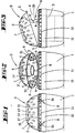
- the dosing reservoir D shown comprises a dosing reservoir pot 1 and one Dosing reservoir cover 2.
- the two parts complement each other accordingly convex curvature and while maintaining a comparable same Wall thickness to a roughly spherical or egg-shaped hollow body.
- the upper and the lower part of the dosing reservoir D merges into a slight flattening, below, i.e. on the bottom of the pot to achieve the adjustability of the dosing reservoir, For example, for the convenient filling of a laundry treatment liquid from above, So from the edge of the pot or the like.
- the dosing reservoir D shown also with pasty to even tablet-shaped Means to be filled. Also on a pellet or granular structure is to be thought here.
- the dosing memory D takes several, relatively large Tablets 3 on the latter are stacked in a disc shape and leave insert into the dosing reservoir D through a side opening 4. The radius the tablets 3 correspond approximately to their height. There are three tablets on top of each other.
- Said opening 4 is achieved by opening the dosing reservoir cover 2.
- the dosing reservoir cover 2 connected to the pot rim in this way has a face 6 for diametrically opposite the fixed joint 5 the convenient opening of the dosage storage lid 2.
- the dosing reservoir D is at least partially perforated. Specifically, it has inlet and outlet openings 7. They are itself in the illustrated embodiment in the dosing reservoir cover 2. It is a relatively uniform perforation is used there. The hole axes run perpendicular to the level pot bottom of the dosing reservoir.
- the wedge-shaped opening position defining the opening 4 is by webs St limited.
- the latter are foldable and stretchable again and cross the said Gap. They are attached to the dosing reservoir pot 1 as the dosing reservoir cover 2 realized in addition to 5 connecting material bridges.
- the fixed joint 5 could also be realized in the form of such a web.
- connection formed by the webs St is designed as a locking device R, with a both in the open position of the metering reservoir lid shown 2 as well as powerfully effective in a closed position Rest position. Overcoming the two rest positions is only a matter of will possible in the closing direction by pressing down the metering reservoir cover 2 and in the opening direction by reaching under the socket 6 by folding up of the dosing reservoir cover 2, for example (if so designed) around the fixed joint 5 going.
- the locking device R is housed in the interior of the dosing reservoir D. It is thus mechanically influenced by the container wall itself protected. They are arranged in pairs. Including the Fixed joint point 5, the two webs St are distributed on the pot edge of the metering device D, that between the three material bridges the same free peripheral section remains. Because the fixed joint 5 on the bisector between the two webs St and relatively far from the free end of the cover, the opening 4 is larger than the length of the webs St.
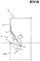
- the locking effect is due to articulation points a, b and c on the web St.
- the first-mentioned articulation point a is the articulation of the web St to the rim of the pot of the dosing reservoir D.
- the second joint point, designated b, is located spaced apart from it.
- the one between the two mentioned articulation points a, b Web section 8 pivots around the hinge point a on a pot rim circular arc path x passing through joint b. Reference is made to FIG. 8.
- the articulation point c is realized as a pivot point towards the metering reservoir cover 2. It is practically a continuation of the wall of the dosing reservoir cover 2 in the web St. The corresponding integral connection is in Fig. 8 indicated.
- the longer web section 9 is directed inward from the substantially vertically aligned inclined leaf spring into the interior of the Dosing reservoir can be bent outwards.
- This hinge point c is set so that it is much less easy to bend than practically due to material reduction hinges a and b designed to form film hinges at both ends of the shorter web section 8. The material reduction is based on training of notch valleys.
- the desired locking or snap action is based on this overall constellation the locking device R by the second articulation point b via a dead center position T-T occurs.
- the web St goes into the respective stable rest position above.
- the restoring force in the direction of arrow y pulls the dosing reservoir lid under the steering action of the web section 8 2 against the edge of the pot, i.e. in the closed position when the hinge point b the zenith of the circular arc x in the horizontal, defined by the dead center plane T-T, has exceeded.
- the same restoring force causes under the steering effect of the shorter web section 8 the strong lifting of the dosing reservoir cover 2, when said joint b mentioned Has exceeded the zenith in the direction of the metering reservoir cover 2.
- the longer one Web section 9 is namely striving to the joint point c back in the to spring back the essential vertical starting position.
- the adapter ring 10 also has inputs and Outflow openings 11, realized, here in the form of Romanesque window arches.
- the front edge of the pot rim is visible on or slightly below the Windowsill of such inflow and outflow openings 11.
- This adapter side Inlet and outlet openings 11 are in addition to the cover-side already mentioned realized.
- the variant of the metering reservoir D shown in FIGS. 5 to 7 is in principle same structure, also with regard to the design of the adapter ring 10.
- the reference numbers are used analogously, sometimes without repeated text.
- there is a modified one Execution with regard to the formation of inflow and outflow openings 12. They are achieved in that the metering storage cover 2 circumferentially at least partially in its connection to the adapter ring 10 there or directly to the dosing reservoir pot 1 to form inlet and side openings Overflow openings 12 is set back.
- the setback goes after inside, i.e. the dome-shaped lid 2 there is transverse to Folding plane, which is identical to the section VII, VII in Fig. 6, partially slightly dented against each other. So arise between the fixed joint 5 and the socket 6 realized in this embodiment narrow crescent-like column (cf. closed position according to FIG. 5).
- the juxtaposition of the rim of the pot and lid as the defined closed position is there interrupted.
- FIG. 4 As for the introduction of, for example, gel-like or pasty laundry treatment agents relates, reference is made to the illustration in FIG. 4. There is based on the metering memory shown in FIGS. 1 to 3. They are here too Transfer reference numbers accordingly. Training continues from the center of the there basically a dome-shaped dosing reservoir cover 1 Opening 13 out. It provides free access to the inside of the Dosing memory D. It is a relatively narrow opening 13. The latter continues like a tube into the interior of said dosing reservoir D.
- the Corresponding tube with a circular cross section is used as a guide cylinder 14 designed. This is based on an essentially flat, ring-shaped Shoulder 15 off. In terms of level, the guide cylinder 14 extends in the closed position of the dosing reservoir D essentially up to the height of the rim of the Dosing storage pot 1.
- Recess 17 and subsequent opening 13 serve to dock a bottle 18, containing the refillable laundry treatment agent.
- the bottle 18 is designed as a squeeze bottle.
- Bottle 18 offering wall sections with corresponding dispensing confirmation can the content of a cylindrical output opening 19 of a cylindrical Apply filler neck 20.
- the filler neck 20 has a so-called push-pull closure. It deals around a stop-limited axially displaceable slide 21 with a corresponding Locking or releasing effect to the leading filler neck 20 that him leads smoothly.
- a gripping bead 22 In the back of the dispensing opening 19 formed by a spout-like mouth there is a gripping bead 22. The latter is supported radially on the inner wall of the described guide cylinder 14 in the docking position (see FIG. 4).
- the filler neck 20 has the Filling bottle 18 a matched to the cylindrical contour of the guide surface 16 Counter contour 23 on.
- the likewise cylindrical counter contour 23 sets over a step 24 into a roughened jacket wall 25 of a bottle closing Screw cap 26 of the bottle 18 on. By loosening the screw cap 26 can fill the bottle 18 itself.
- this supports the dispensing opening facing downwards 19 delivered bottle 18 axially spaced radially, and once in the area of the gripping bead 22 in the end zone on the inside of the accumulator of the guide cylinder 14 and again at the beginning, namely on or between the cross-sectional guide surface 16 and the screw cap side Counter contour 23.
- the inner wall of the dosing reservoir pot 1 and / or the dosing reservoir cover 2 is roughened. About the correspondingly abrasive Effect the dissolution of the detergent tablets 3 is accelerated.
- the dosing reservoir D according to the variant in FIG. 5 is not with regard to an adjustability designed; it has more of a structure approximating the spherical shape.
- the dosing reservoir D can be made of transparent or translucent material be formed and have metering marks.
- the detachability of the dosing storage pot allows its use as a washing powder etc. scoop dosing device.
Landscapes
- Engineering & Computer Science (AREA)
- Textile Engineering (AREA)
- Closures For Containers (AREA)
- Detergent Compositions (AREA)
Abstract
Description
- Fig. 1
- den erfindungsgemäß ausgebildeten Dosierspeicher in Vorderansicht, geschlossen,
- Fig. 2
- denselben in gleicher Darstellung, jedoch geöffnet,
- Fig. 3
- den geöffneten Dosierspeicher in Seitenansicht,
- Fig. 4
- den Dosierspeicher in geschlossenem Zustand unter Verdeutlichung einer Andocksituation zwecks Einbringung eines Wäschebehandlungsmittels in denselben,
- Fig. 5
- die Draufsicht auf eine Variante des Dosierspeichers in Schließstellung, unter Verdeutlichung hier die Ein- und Ausströmöffnungen bildender Spalte,
- Fig. 6
- diesem Dosierspeicher in gleicher Darstellung, jedoch bestückbar geöffnet,
- Fig. 7
- den Schnitt gemäß der Linie VII-VII in Fig. 6 und
- Fig. 8
- eine weitestgehend schematisierte Bewegungsstudie im Bereich des die Rasteinrichtung bringenden Steges, und zwar in über eine Totpunktebene getretener Zwischenstellung.
Claims (7)
- Dosierspeicher (D), bestehend aus einem Dosierspeicher-Topf (1) und einem Dosierspeicher-Deckel (2), bildend ein Speichergehäuse zur Aufnahme und Abgabe eines flüssigen, pastösen oder auch tablettenförmigen Wäschebehandlungsmittels, zur Verwendung in einem mit einer Waschmaschine durchzuführenden Waschverfahren, welcher Dosierspeicher (D) Ein- und Ausströmöffnungen (7) aufweist, weiter eine zentrale Öffnung (13) besitzt, an die eine Flasche (18) andockbar ist, und dazu einen Rohrfortsatz aufweist, welcher, ausgehend von einer im wesentlichen ebenflächigen Schulter (15), sich in das Innere des Speichergehäuses erstreckt, dadurch gekennzeichnet, daß der Rohrfortsatz einen Führungszylinder (14) aufweist zur verkippsicheren Abstützung und Andockführung eines angepaßten Füllstutzens (20) der Flasche (18).
- Dosierspeicher nach Anspruch 1, dadurch gekennzeichnet, daß der Füllstutzen (20) im wesentlichen zylindrisch ist und eine stirnseitige Ausgabeöffnung (19) besitzt.
- Dosierspeicher nach Anspruch 1, dadurch gekennzeichnet, daß die Schulter (15) von einer sich im wesentlichen rechtwinklig zur Schulter (15) erstreckenden Führungsfläche (16) umgeben ist.
- Dosierspeicher nach Anspruch 1, dadurch gekennzeichnet, daß der Führungszylinder (14) im wesentlichen auf Höhe eines Randes des Dosierspeicher-Deckels (2) endet.
- Dosierspeicher nach einem oder mehreren der vorhergehenden Ansprüche, dadurch gekennzeichnet, daß der Füllstutzen (20) eine auf die Führungsfläche (16) abgestimmte Gegenkontur (23) besitzt.
- Dosierspeicher nach Anspruch 5, dadurch gekennzeichnet, daß die Gegenkontur (23) sich über eine Stufe (24) in die Mantelwand einer die Flasche (18) verschließenden Schraubkappe (26) fortsetzt.
- Dosierspeicher nach einem oder mehreren der vorhergehenden Ansprüche, dadurch gekennzeichnet, daß der Füllstutzen (20) einen Verschluß-Schieber (21) aufweist, der sich in der speicherinnenseitigen Endzone radial an der Innenwandung des Führungszylinders (14) abstützt.
Applications Claiming Priority (3)
| Application Number | Priority Date | Filing Date | Title |
|---|---|---|---|
| DE19547639A DE19547639C1 (de) | 1995-12-20 | 1995-12-20 | Dosierspeicher |
| DE19547639 | 1995-12-20 | ||
| EP96119755A EP0780508B1 (de) | 1995-12-20 | 1996-12-10 | Dosierspeicher |
Related Parent Applications (1)
| Application Number | Title | Priority Date | Filing Date |
|---|---|---|---|
| EP96119755A Division EP0780508B1 (de) | 1995-12-20 | 1996-12-10 | Dosierspeicher |
Publications (2)
| Publication Number | Publication Date |
|---|---|
| EP1016751A2 true EP1016751A2 (de) | 2000-07-05 |
| EP1016751A3 EP1016751A3 (de) | 2003-03-19 |
Family
ID=26021450
Family Applications (1)
| Application Number | Title | Priority Date | Filing Date |
|---|---|---|---|
| EP00102506A Withdrawn EP1016751A3 (de) | 1995-12-20 | 1996-12-10 | Dosierspeicher |
Country Status (1)
| Country | Link |
|---|---|
| EP (1) | EP1016751A3 (de) |
Family Cites Families (3)
| Publication number | Priority date | Publication date | Assignee | Title |
|---|---|---|---|---|
| FR2587001B1 (fr) * | 1985-09-11 | 1990-02-09 | Procter & Gamble France | Dispositif doseur et diffuseur, pouvant etre incorpore a un recipient, en particulier pour produits liquides |
| FR2592001B1 (fr) * | 1985-12-23 | 1992-07-17 | Procter & Gamble France | Bouchon de recipient, en particulier pour produits liquides, agences comme dispositif doseur et diffuseur et procede, notamment pour le lavage du linge en machine, mettant en oeuvre ledit bouchon |
| FR2611759B1 (fr) * | 1987-03-04 | 1990-02-02 | Savonnerie Union Generale | Dispositif doseur et distributeur d'un produit fluide, a deposer librement dans l'enceinte mobile d'une machine |
-
1996
- 1996-12-10 EP EP00102506A patent/EP1016751A3/de not_active Withdrawn
Also Published As
| Publication number | Publication date |
|---|---|
| EP1016751A3 (de) | 2003-03-19 |
Similar Documents
| Publication | Publication Date | Title |
|---|---|---|
| DE69413845T2 (de) | Knebelbetätigter spenderverschluss | |
| DE69202650T2 (de) | Zwei-Flaschen-Verpackung zur getrennten Aufbewahrung von zwei Produkten, insbesondere flüssigen und zur Mischung derselben vor dem Gebrauch. | |
| DE69500423T2 (de) | Spenderkoppe für vakuumfleschen | |
| DE69607800T2 (de) | Vorrichtung zum Verschliessen eines Behälters und zur Abgabe des Behälterinhalts | |
| EP1233915B1 (de) | Standbeutel mit umknickbarem verschlusselement | |
| DE68909789T2 (de) | Augentropfenverabreichungsvorrichtung. | |
| EP0515348B1 (de) | Garantieverschluss | |
| DE69716808T2 (de) | Flasche zum getrennten Aufbewaren von Substanzen welche vor dem Ausgeben gemischt werden müssen | |
| DE3514132A1 (de) | Behaelterverschluss | |
| DE19549440C2 (de) | Dosierspeicher | |
| EP0363307A1 (de) | Als Spender für pastöse Produkte ausgebildete Dose | |
| EP0652158A1 (de) | Vorrichtung zum Halten einer im wesentlichen zylinderförmigen Flasche | |
| AT398299B (de) | Giesseinsatzelement | |
| DE3829969C1 (de) | ||
| DE69302185T2 (de) | Selbstschliessende Ausgabevorrichtung für einen eine pastöse Flüssigkeit enthaltenden Behälter | |
| DE3416008A1 (de) | Dosiergeraet | |
| DE60036824T2 (de) | Verschlusskappe | |
| CH671385A5 (de) | ||
| EP0087562B1 (de) | Spender zur Abgabe flüssiger, pastöser oder staubförmiger Füllgüter | |
| DE19547639C1 (de) | Dosierspeicher | |
| DE2026526C3 (de) | Sicherheitskappe für eine Sprühdose | |
| DE837298C (de) | Selbsttaetiger Verschluss fuer Behaelter, die gleichzeitig als Giesser, Verteiler, Dosierer oder Zerstaeuber dienen | |
| EP2431294B1 (de) | Drehverschluss für Kosmetikbehälter | |
| DE69701287T2 (de) | Bausatz für einen behälterverschluss | |
| DE2850505A1 (de) | Kindersichere packung |
Legal Events
| Date | Code | Title | Description |
|---|---|---|---|
| PUAI | Public reference made under article 153(3) epc to a published international application that has entered the european phase |
Free format text: ORIGINAL CODE: 0009012 |
|
| 17P | Request for examination filed |
Effective date: 20000205 |
|
| AC | Divisional application: reference to earlier application |
Ref document number: 780508 Country of ref document: EP |
|
| AK | Designated contracting states |
Kind code of ref document: A2 Designated state(s): AT BE CH DE DK ES FR GB IT LI NL |
|
| PUAL | Search report despatched |
Free format text: ORIGINAL CODE: 0009013 |
|
| AK | Designated contracting states |
Kind code of ref document: A3 Designated state(s): AT BE CH DE DK ES FR GB IT LI NL Designated state(s): AT BE CH DE DK ES FR GB IT LI NL |
|
| AKX | Designation fees paid |
Designated state(s): AT BE CH DE DK ES FR GB IT LI NL |
|
| STAA | Information on the status of an ep patent application or granted ep patent |
Free format text: STATUS: THE APPLICATION IS DEEMED TO BE WITHDRAWN |
|
| 18D | Application deemed to be withdrawn |
Effective date: 20020102 |