EP1016367B1 - Breaded products fryer - Google Patents
Breaded products fryer Download PDFInfo
- Publication number
- EP1016367B1 EP1016367B1 EP99310253A EP99310253A EP1016367B1 EP 1016367 B1 EP1016367 B1 EP 1016367B1 EP 99310253 A EP99310253 A EP 99310253A EP 99310253 A EP99310253 A EP 99310253A EP 1016367 B1 EP1016367 B1 EP 1016367B1
- Authority
- EP
- European Patent Office
- Prior art keywords
- oil
- fryer
- conveyor
- product
- cooking
- Prior art date
- Legal status (The legal status is an assumption and is not a legal conclusion. Google has not performed a legal analysis and makes no representation as to the accuracy of the status listed.)
- Expired - Lifetime
Links
Images


Classifications
-
- A—HUMAN NECESSITIES
- A47—FURNITURE; DOMESTIC ARTICLES OR APPLIANCES; COFFEE MILLS; SPICE MILLS; SUCTION CLEANERS IN GENERAL
- A47J—KITCHEN EQUIPMENT; COFFEE MILLS; SPICE MILLS; APPARATUS FOR MAKING BEVERAGES
- A47J37/00—Baking; Roasting; Grilling; Frying
- A47J37/12—Deep fat fryers, e.g. for frying fish or chips
- A47J37/1214—Deep fat fryers, e.g. for frying fish or chips the food being transported through an oil-bath
-
- A—HUMAN NECESSITIES
- A47—FURNITURE; DOMESTIC ARTICLES OR APPLIANCES; COFFEE MILLS; SPICE MILLS; SUCTION CLEANERS IN GENERAL
- A47J—KITCHEN EQUIPMENT; COFFEE MILLS; SPICE MILLS; APPARATUS FOR MAKING BEVERAGES
- A47J37/00—Baking; Roasting; Grilling; Frying
- A47J37/12—Deep fat fryers, e.g. for frying fish or chips
- A47J37/1233—Deep fat fryers, e.g. for frying fish or chips the frying liquid being heated outside the frying vessel, e.g. by pumping it through a heat exchanger
- A47J37/1238—Deep fat fryers, e.g. for frying fish or chips the frying liquid being heated outside the frying vessel, e.g. by pumping it through a heat exchanger and the oil being returned to the frying vessel by means of a spraying system
Definitions
- This invention in general pertains to food products prepared in cooking oil or oil substitutes and concerns more particularly an improved method and apparatus for frying products especially battered and breaded products in a manner whereby the breaded coating remains substantially intact as the product is conveyed continuously through the frying system.
- a number of successfully marketed food products, chicken, beef, fish, filled dough, vegetables, etc. are prepared by coating or battering the product and covering the coating with bread crumbs or the like and frying thereafter.
- the frying step in which the product is either partially or fully cooked, it is highly desirable that as much of the breading or other coating be retained on the product and that a very minimum of the coating slough off into the cooking oil.
- particles of the coating break away from the product, this results in a lower production yield and the fines sloughed off contaminate the frying oil.
- These breading and product fines must be removed from the frying medium on a regular basis to avoid degrading the cooking oil to a point where it must be supplemented by a higher quality oil or else removed for recycling.
- US 4882984 (Raytheon Company, 1989) shows a conveyor fryer, submerging food product in hot cooking oil, between underlying conveyor run supports and overlying restraints.
- a fryer (10), for frying a food product (19), in hot cooking oil comprises:
- the reservoir (29) can be configured as a trough, bounded by horizontal weir shoulders (31), defining the reservoir top and oil surface level; an oil inlet delivery conduit (33), with discharge openings along its underside, running the length of the reservoir trough (29), to supply oil to the reservoir from the bottom, beneath the oil surface; and thereby to displace oil from the surface, over the shoulders (31), downwardly along depending weir guide walls or skirts (32), and in free-fall therefrom, in a continuous curtain (28), to contact and enrobe food product (19) upon an underlying conveyor (18).
- an oil inlet delivery conduit (33) with discharge openings along its underside, running the length of the reservoir trough (29), to supply oil to the reservoir from the bottom, beneath the oil surface; and thereby to displace oil from the surface, over the shoulders (31), downwardly along depending weir guide walls or skirts (32), and in free-fall therefrom, in a continuous curtain (28), to contact and enrobe food product (19) upon an
- the endless conveyor (18) could include a return run arranged in said pan (14), to sweep the bottom surface of the pan, serving to move to one end of the pan any product fines, pieces or particles dislodged during processing in the fryer (10), and fines removal means, arranged at one end of the pan, for withdrawal of the fines from the fryer.
- a product hold-down conveyor (26) could be arranged in the housing (16), above the first mentioned conveyor (18), and serve to maintain food products (19), substantially in their original positions, during the treatment process in the fryer, the hold-down conveyor being equipped with an oil pervious conveyor belt, permitting oil dispensed from the distribution stations (27) to flow freely therethrough.
- a deadplate baffle (37) could be arranged underneath an upper run of the conveyor (18), and configured with openings (38), through said deadplate baffle, to direct downwards cooking oil poured from the distribution stations (27), and then causing the oil to move generally parallel to the direction of conveyor travel, and underneath the deadplate baffle, toward an oil removal station provided in the pan.
- the cooking oil distribution stations (27) could each be provided with two weirs (31), serving to establish two curtains of smooth flowing cooking oil (28) at each distribution station.
- a plurality of distribution stations (27) could be provided in the housing, at least one of the stations being disposed at a different elevation from that of an adjacent station.
- the conveyor belt (18) could be inclined upwardly, adjacent to the end of the cooking zone where the product (16) exits the housing.
- the process could include providing the endless conveyor with a return run, in substantial contact with the fryer bottom, and moving product fines to a fines removal zone, through the action of the conveyor return run.
- the process could also include providing for removal of the cooking oil from the fryer, by flowing the oil in the fryer, in spaced apart longitudinal paths, extending longitudinally of the product conveyor, substantially isolated from the food products being conveyed through the fryer.
- Another process option includes supplying the cooking oil in a plurality of curtains, extending transversely of the path of the product carrying conveyor.
- the cooking oil could be delivered to the curtains, at different temperatures, such that the food products are subjected to varying oil temperatures, while being conveyed on the product conveyor.
- the volume of cooking oil in the fryer could be maintained at a level below the top run of the product conveyor, such that food products carried on the conveyor are not submersed in the cooking oil during treatment.
- the volume of cooking oil in the fryer could be maintained at a level above the top run of the product conveyor, such that food products carried on the conveyor are at least partially submersed in the cooking oil during treatment.
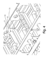
- the improved fryer 10 includes a frame 11 supported by four upstanding legs 12 provided with level adjustment mechanisms 13 which are operable to enable a uniform, accurate vertical flow pattern of the cooking oil which will be described in more detail below. It is desirable that the frame which supports a pan 14, which retains the cooking oil supply prior to its return for reheating, be maintained level both fore and aft as well as side to side for smooth even flow of the oil curtains.
- a hood 16 is mounted on the frame 11 and is equipped with an exhaust stack 17 which serves for the removal of cooking vapors generated beneath the hood 16 and to enable those vapors to be conveyed to a treatment facility (not shown) so as to minimize atmosphere contamination.
- a product carrying conveyor 18 is arranged in the pan 14 for moving products 19 deposited thereon from an inlet 21 to an outlet 22.
- the product conveyor 18 is configured with an inside return so that the conveyor belt, which may be of woven wire mesh or other suitable material affording oil pervious construction, returns along the bottom of the pan 14 moving from right to left, as viewed in FIG. 2, so as to sweep any product fines or residue into the sump 23 for removal therefrom through the conduit 24.
- the width of the conveyor 18 is such that it extends substantially the full width of the fryer so that the return run will sweep the pan bottom completely of product fines. It will be understood that the product carrying conveyor 18 receives products transferred thereto through the fryer inlet 21 at the left of FIG. 2 and conveys the product towards the fryer outlet 22.
- the outlet end of the conveyor is inclined upwardly so as to raise the treated food products 19 out of contact with the cooking oil and thence for subsequent removal from the fryer 10.
- the top or product carrying run of the conveyor 18 may operate either above or below the oil liquid level maintained in the pan 14.
- the selection and control of the cooking oil depth in the pan 14 with respect to the food products on the conveyor top run is determined by the product cooking specifications and more specifically whether it is desirable to have the lower portions of the product conveyed through the cooking oil or to be moved above the cooking oil liquid level.
- the product conveyor 18 is driven through a variable speed motor drive 23 (FIG. 1) which affords an accurate rate of progression for treatment of the products 19 moving through the fryer 10.
- Typical products 19 which are treated in the fryer 10 include, for example, onion rings as well as other vegetables; meats such as chicken and beef as well as fish. These food products may be first dipped in a viscous batter and then covered with a layer of bread crumbs or similar coating which adheres to the batter, thus increasing the weight of the product. Unless handled carefully in the cooking operation, a portion of the breading or other coating will not adhere to the product and will fall into the cooking oil which is undesirable as discussed above. Described below are steps which materially reduce the amount of bread and batter material stripped from the product through the cooking operation.
- Certain products tend to move, tumble or shift as they are carried on the conveyor 18 or to "float" in cooking oil residing in the pan 14. For these reasons it is desirable to arrange a hold-down conveyor system 26 under the hood such that the lower run of the hold-down conveyor is positioned to engage the upper surfaces of the product 19 and maintain the food product in its initial position on the main conveyor during the cooking process .
- the vertical position of the hold-down conveyor may be varied to accommodate products 19 of different vertical dimensions.
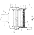
- the conveyor belt of the hold-down conveyor 26 is of wire mesh construction to permit the easy flow there through of the cooking oil dispensed from the cooking oil distribution stations 27 arranged above the conveyor 18 carrying the products 19, as clearly shown in FIGS. 2 and 3.
- One desirable oil level 30 is indicated in FIG. 2 as coextensive with the lower run of the conveyor 26. I will be understood that the conveyor 26 may be shifted vertically to either engage or be disengaged from a particular size of product and the oil level 30 may be adjusted to accommodate particular processes and products.
- the oil distribution stations 27, best shown in FIGS. 3 and 4, extend laterally of the conveyor belt 18 and are substantially co-extensive of the width of the conveyor belt so that the full width of the belt may serve as a food cooking area as shown in FIG. 5.
- the conveyor belt and the distribution stations extend fully with only marginal clearances between the two sides of the fryer as indicated in FIG. 5.
- the stations 27 serve to distribute or pour hot cooking oil onto the products 19 carried by the belt 18 through at least one and preferably a plurality of curtains 28 of smooth, virtually ripple-free cooking oil.
- cooking oil as used herein is intended to embrace oil substitutes such as Olean or Olestra which are trademarks of Proctor and Gamble, Co.
- the incoming hot cooking oil flows from a laterally extending, horizontally disposed trough 29 of relatively small volume as compared to that of the pan.
- the trough 29 is provided with two upwardly rising, smoothly contoured shoulders 31 which merge into descending guide walls or skirts 32.
- a delivery conduit 33 which is provided with oil discharge openings along its bottom perimeter, the openings being positioned below and between the shoulders 31.
- Incoming oil flows from the conduit 33 to fill the trough 29 from the bottom up to the level of the shoulders from whence the weir action occurs.
- the spaced apart, horizontally disposed shoulders 31 serve to define or establish the top oil surface in the distribution station. This surface is above the oil discharge openings of the delivery conduit 33. Thus, as incoming oil flows into the trough 29 a corresponding volume of oil flows from the top or overflow oil surface. Thus the cooking oil overflows over the smoothly contoured shoulders 31 and downwardly along the guide walls or skirts 32. This creates the weir action and establishes the flow curtains 28 of cooking oil which contact the products in an enrobing action for cooking.
- the vertical drop of the oil or vertical length of the oil curtains is dictated somewhat by the product height and for this reason the distribution stations include means 35 permitting vertical adjust for raising or lowering and accurate leveling of the stations with respect to the main conveyor belt.
- the delivery conduits 33 are supplied from a manifold 34, FIGS. 1 and 4, including the cross supply tubes 36.
- the manifold 34 is connected to an oil supply from a heat exchanger or the like (not shown) for delivery of oil to the distribution stations 27 at a precise flow rate and temperature.
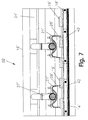
- the cooking oil then flows through the conveyor belts and through openings 38 in the deadplate or false bottom 37, shown best in FIG. 4.
- the areas and locations of the openings 38 may be selected to compensate for dynamic pressure differences in the oil flowing under the deadplate 37 so as to minimize any longitudinal oil flow through the product zone above the conveyor 18.
- the oil flows longitudinally along the pan 14 as indicated by the lower arrows in FIG. 2 in the relatively shallow space between the deadplate 37 and the pan bottom in a flow pattern which is substantially uniform across the full width of the fryer. From one viewpoint, the pan 14 serves merely to contain the cooking oil for recirculation and reheating as contrasted to the prior art fryers where all of the product cooking was conducted under turbulent condition within the oil bath maintained in the pan.
- the oil is discharged through the conduit 24 and is circulated to the heat exchanger (not shown) for reheating and return to the fryer at a preselected input initial temperature.
- the deadplate 37 may function as a puddler panel as it is arranged along the distribution stations 27 and is disposed underneath the infeed run of the conveyor.
- the panel is co-extensive with the width of the conveyor belt.
- the panel functions to collect with the opening s in the wire belt a meniscus or puddle of hot cooking oil flowing unto it from the oil curtains above. The oil puddle wets the bottom of the food product to transfer additional heat to the product. This is a efficient arrangement to ensure oil treatment to the lower portions and the bottom of a food product where it is undesirable to fully immerse the lower portions of the product in cooking oil.
- An improved breaded products fryer 10 having four oil inlet distribution stations 27 each with two oil overflow weirs 31, 32 and a variable-speed product-carrying conveyor 18, 23 was operated in accordance with the principles of the present invention.
- a first group of product samples 19 were fried for a range of processing times in the fryer 10, with sufficient oil level to fully submerge all samples.
- Another group of product samples were fried in the same fryer 10 but with the oil level below the perforated deadplate 37.
- Sets of control samples were fried either in a conventional breaded products fryer (not shown) or in a still-bath batch fryer, to provide a basis for comparison of cooking times and finished product quality.
- Chicken breasts without any coating were fried at 365°F for times between 30 seconds and 3 minutes, to compare processing times. There was no measurable difference, as determined by the depth of visible color change, between those samples fried submerged in oil in the improved breaded products fryer 10 and those fried for the same lengths of time in the conventional fryer. Samples fried in the fryer 10 but with the oil level below the perforated deadplate 37 required approximately 25% longer total cooking time to show equivalent depths of visible color change.
- Thick potato slices without any coating were fried at 365°F for times between 30 seconds and 3 minutes, to compare processing times. There was no measurable difference, as determined by the depth of visible opacity change, between those samples fired submerged in oil in the breaded products fryer 10 and those fried for the same lengths of time in the conventional fryer. Samples treated in the fryer 10 but with the oil levels below the perforated deadplate 37 appeared to require approximately 25% longer total cooking time to show equivalent depths of visible opacity change.
- Chicken breasts were battered and flour-coated, then fried at 365°F in the breaded products fryer 10 with the oil level below the perforated deadplate 37.
- the product conveyor 18 was advanced manually to simulate a greater range of weir spacing, number of weirs and processing times. Control samples were fried in a batch fryer for 40 seconds at 365°F.
- Chicken breasts were battered and coated with "J" crumbs, then fried in the fryer 10, for 40 seconds at the closest simulated weir spacing, with the oil level below the perforated deadplate 37. Some were fried directly while others were pre-treated by immersion in a still-bath batch fryer for 5 seconds immediately prior to entering the improved breaded products fryer. Control samples were batch fried.
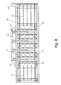
- FIGS. 6-8 A second preferred embodiment of the invention 40 is shown in FIGS. 6-8 and this fryer is constructed in accordance with and embodies the principles of the present invention. Where previously described corresponding parts are indicated in the drawings these are identified with a "prime” (').
- the fryer 40 has an inclined inlet section of the conveyor 18' as well as an incline outlet section, as is apparent from FIG. 6.
- the oil level 30' extends over the top of the product 19' or in other words the products are treated in the fryer in a submerged condition. There is no hold down conveyor present in the embodiment 40 which then is most useful for products 19' which do not tend to float or in which the floating of the product in the oil is within the intended operating parameters.
- the bottom run of the conveyor 18' is closely spaced with respect to the pan bottom so as in operation to sweep the bottom of the pan 14'.
- the top run of the conveyor 18 is guided and supported by lane guides 42 which are so positioned with respect to the fryer bottom to define oil return paths as indicated by the arrows 43 in FIG. 8. More specifically, the oil return paths are from the central portion of the fryer to the side and then to urge the oil to migrate toward the sump 24' for removal from the fryer to a reheating unit.
- the lane guides 42 serve with the conveyor runs to define oil passageways over the fryer bottom for removal of the oil and its recirculation. Five such lane guides 42 are indicated in FIG. 8 although the number may be higher or lower depending upon the width of the fryer and the return flow rate desired.
- FIG. 9 A third preferred embodiment of the invention 50 is shown in FIG. 9 and this fryer is construction in accordance with and embodies the principles of the present invention. Where previously described corresponding parts are indicated in the drawing, these are identified with a "prime" (').
- the improved breaded products fryer 50 is constructed with parts previously identified and in this instance includes a principal products conveyor 43 which is configured for an outside return. That is to say the return of the conveyor does not travel across the inside of the pan, but returns outside of the pan as indicated in FIG. 9.
- the top run of the conveyor is arranged to sweep the bottom of the pan and to move any fines that develop in the frying process toward the sump 24' which is positioned adjacent to the discharge end of the fryer.
Applications Claiming Priority (2)
| Application Number | Priority Date | Filing Date | Title |
|---|---|---|---|
| US09/222,547 US6067899A (en) | 1998-12-29 | 1998-12-29 | Breaded products fryer |
| US222547 | 1998-12-29 |
Publications (2)
| Publication Number | Publication Date |
|---|---|
| EP1016367A1 EP1016367A1 (en) | 2000-07-05 |
| EP1016367B1 true EP1016367B1 (en) | 2002-11-20 |
Family
ID=22832662
Family Applications (1)
| Application Number | Title | Priority Date | Filing Date |
|---|---|---|---|
| EP99310253A Expired - Lifetime EP1016367B1 (en) | 1998-12-29 | 1999-12-20 | Breaded products fryer |
Country Status (8)
| Country | Link |
|---|---|
| US (2) | US6067899A (ja) |
| EP (1) | EP1016367B1 (ja) |
| JP (1) | JP3380507B2 (ja) |
| AT (1) | ATE227954T1 (ja) |
| AU (1) | AU738066B2 (ja) |
| CA (1) | CA2293037C (ja) |
| DE (1) | DE69904012T2 (ja) |
| ZA (1) | ZA997859B (ja) |
Families Citing this family (28)
| Publication number | Priority date | Publication date | Assignee | Title |
|---|---|---|---|---|
| US6067899A (en) * | 1998-12-29 | 2000-05-30 | Heat & Control, Inc. | Breaded products fryer |
| US7337594B2 (en) * | 2002-04-22 | 2008-03-04 | Restaurant Technology, Inc. | Food dispensing device and method |
| US20030205028A1 (en) * | 2002-04-22 | 2003-11-06 | Sus Gerald A. | Automated food processing system and method |
| US6871676B2 (en) * | 2002-04-22 | 2005-03-29 | Restaurant Technology, Inc. | Automated device and method for packaging food |
| US6869633B2 (en) * | 2002-04-22 | 2005-03-22 | Restaurant Technology, Inc. | Automated food frying device and method |
| CA2483414A1 (en) * | 2002-04-22 | 2003-10-30 | Restaurant Technology, Inc. | Automated food processing system and method |
| US20060083831A1 (en) * | 2004-10-14 | 2006-04-20 | Caridis Andrew A | Forming and cooking with controlled curtain spillage |
| US8017166B2 (en) * | 2004-11-01 | 2011-09-13 | Steven Amory Twitty | Method of producing stackable low-fat snack chips |
| US8318229B2 (en) * | 2005-01-24 | 2012-11-27 | Frito-Lay North America, Inc. | Method for controlling bulk density of fried snack pieces |
| US20170311757A1 (en) * | 2016-04-29 | 2017-11-02 | Alan Backus | Devices and methods for supporting and preparing foods |
| JP4883784B2 (ja) * | 2006-12-04 | 2012-02-22 | 株式会社冨士製作所 | 食品の油揚げ装置 |
| US8464635B1 (en) * | 2008-01-17 | 2013-06-18 | Alkar-Rapidpak-Mp Equipment, Inc. | Frying system |
| EP2542132B1 (en) | 2010-03-01 | 2014-05-07 | PPM Technologies, LLC | Batch cooker |
| US20120070553A1 (en) | 2010-09-20 | 2012-03-22 | Conagra Foods Lamb Weston, Inc. | Conveyor-based frying apparatus and methods of use |
| CN102772149B (zh) * | 2011-05-12 | 2016-07-06 | 乐金电子(天津)电器有限公司 | 烤箱的接油装置 |
| US8945648B2 (en) | 2011-11-30 | 2015-02-03 | Frito-Lay North America, Inc. | Fried food product with reduced oil content |
| US10548341B2 (en) | 2011-11-30 | 2020-02-04 | Frito-Lay North America, Inc. | Potato chip |
| CN102940454B (zh) * | 2012-11-29 | 2015-09-23 | 余姚市吉佳电器有限公司 | 一种滚轴式喷酱烤面包机 |
| CN102940455B (zh) * | 2012-11-29 | 2015-08-19 | 余姚市吉佳电器有限公司 | 一种滚轴式涂酱烤面包机 |
| US10123555B2 (en) | 2013-04-19 | 2018-11-13 | Frito-Lay North America, Inc. | Method, apparatus and system for producing a food product |
| US9226523B2 (en) * | 2013-07-19 | 2016-01-05 | Fremont Beef Company | Method and means for extending the shelf life of food products |
| RU2567655C1 (ru) * | 2015-01-20 | 2015-11-10 | Олег Иванович Квасенков | Способ производства печёных пирожков с рыбной начинкой |
| EP3167779B1 (de) * | 2015-11-11 | 2020-03-18 | Neumayer, Harald | Erhitzungsverfahren zum erhitzen von gütern, insbesondere lebensmitteln, sowie eine erhitzungsvorrichtung zur durchführung des verfahrens |
| GB201609650D0 (en) * | 2016-06-02 | 2016-07-20 | Icelandic Group Uk Ltd | Improvements in or relating to the coating of food with batter |
| GB2552820A (en) * | 2016-08-11 | 2018-02-14 | Frito Lay Trading Co Gmbh | Handling snack food chips |
| US11147418B2 (en) | 2017-04-07 | 2021-10-19 | Henny Penny Corporation | Automated fryer |
| CA3133052A1 (en) * | 2019-03-26 | 2020-10-01 | Gea Food Solutions Bakel B.V. | Floating particles removal within a food fryer |
| CN115316688A (zh) * | 2022-08-17 | 2022-11-11 | 峨眉山沐之源食品有限公司 | 一种熟食生产预煮装置 |
Family Cites Families (23)
| Publication number | Priority date | Publication date | Assignee | Title |
|---|---|---|---|---|
| DE2444746B2 (de) * | 1974-09-19 | 1976-08-26 | Neff- Werke, Carl Neff Gmbh, 7518 Bretten | Friteuse mit umlaufendem transportband |
| US4167585A (en) * | 1976-03-01 | 1979-09-11 | Heat And Control, Inc. | Method for heating and cooking foods in a closed treatment chamber by maintaining the temperature and moisture content |
| US4386559A (en) * | 1980-12-09 | 1983-06-07 | General Foods Corporation | Apparatus for continuous preparation of reconstitutable batter-coated comestibles |
| US4439459A (en) * | 1982-03-08 | 1984-03-27 | Swartley John S | Convection food heating |
| JPH0238206B2 (ja) * | 1982-06-02 | 1990-08-29 | Takahisa Komatsubara | Aburasanpushikichoriki |
| JPH0114273Y2 (ja) * | 1985-02-07 | 1989-04-26 | ||
| DE3786400T2 (de) * | 1986-04-23 | 1994-02-17 | Vos Ind Pty Ltd | Kochvorrichtung. |
| FR2622783B1 (fr) * | 1987-11-09 | 1994-04-01 | Grandi Rene | Dispositif d'unite de cuisson a differents moyens:par immersion ou pulverisation d'huile,d'eau ou de vapeur sous pression,avec filtrage en continu et refroidissement en fin de cycle |
| US4852475A (en) * | 1988-04-25 | 1989-08-01 | Yang Chen Shi | Continuous processing machine assembly for frying raw materials |
| US4942810A (en) * | 1988-09-15 | 1990-07-24 | Lyco Manufacturing, Inc. | Water seal blancher |
| US4882984A (en) * | 1988-10-07 | 1989-11-28 | Raytheon Company | Constant temperature fryer assembly |
| US5020426A (en) * | 1989-06-26 | 1991-06-04 | Valley Grain Products, Inc. | Food product cooker |
| US5074199A (en) * | 1989-09-22 | 1991-12-24 | Stein, Inc. | Deep fat fryer with upwardly and downwardly movable conveyor and heating apparatus |
| US5666876A (en) * | 1991-12-20 | 1997-09-16 | Vos Industries Ltd. | Cooking apparatus |
| US5615606A (en) * | 1991-12-20 | 1997-04-01 | Vos Industries Pty. Ltd. | Conveyor |
| US5322006A (en) * | 1992-03-31 | 1994-06-21 | House Food Industrial Co., Ltd. | Continuous frying apparatus |
| SG47825A1 (en) | 1992-05-26 | 1998-04-17 | Vos Ind Ltd | A cooking apparatus |
| JP2693687B2 (ja) * | 1992-05-27 | 1997-12-24 | 日清食品株式会社 | 油揚麺類の製造方法及びそのための装置 |
| US5253567A (en) * | 1993-03-05 | 1993-10-19 | Stein, Inc. | Thermal fluid heat exchanger for deep fat fryer |
| US5580598A (en) * | 1995-11-03 | 1996-12-03 | Heat And Control. Inc. | Multi-product food cooking system |
| US5786015A (en) * | 1996-04-09 | 1998-07-28 | B. C. Rogers Poultry, Inc. | Method for producing food grade poultry oil and meal |
| US5795608A (en) * | 1996-08-05 | 1998-08-18 | Hachitei Corporation | Process for preparing coating particles used for a fried food |
| US6067899A (en) * | 1998-12-29 | 2000-05-30 | Heat & Control, Inc. | Breaded products fryer |
-
1998
- 1998-12-29 US US09/222,547 patent/US6067899A/en not_active Expired - Lifetime
-
1999
- 1999-12-20 EP EP99310253A patent/EP1016367B1/en not_active Expired - Lifetime
- 1999-12-20 DE DE69904012T patent/DE69904012T2/de not_active Expired - Lifetime
- 1999-12-20 AT AT99310253T patent/ATE227954T1/de not_active IP Right Cessation
- 1999-12-22 CA CA002293037A patent/CA2293037C/en not_active Expired - Fee Related
- 1999-12-23 ZA ZA9907859A patent/ZA997859B/xx unknown
- 1999-12-24 AU AU65497/99A patent/AU738066B2/en not_active Ceased
-
2000
- 2000-01-04 JP JP2000000151A patent/JP3380507B2/ja not_active Expired - Fee Related
- 2000-01-31 US US09/494,971 patent/US6558724B1/en not_active Expired - Lifetime
Also Published As
| Publication number | Publication date |
|---|---|
| ATE227954T1 (de) | 2002-12-15 |
| CA2293037A1 (en) | 2000-06-29 |
| JP3380507B2 (ja) | 2003-02-24 |
| DE69904012D1 (de) | 2003-01-02 |
| AU6549799A (en) | 2000-09-07 |
| DE69904012T2 (de) | 2003-10-02 |
| US6067899A (en) | 2000-05-30 |
| CA2293037C (en) | 2004-06-01 |
| AU738066B2 (en) | 2001-09-06 |
| JP2000217720A (ja) | 2000-08-08 |
| ZA997859B (en) | 2000-07-05 |
| EP1016367A1 (en) | 2000-07-05 |
| US6558724B1 (en) | 2003-05-06 |
Similar Documents
| Publication | Publication Date | Title |
|---|---|---|
| EP1016367B1 (en) | Breaded products fryer | |
| EP1105001B1 (en) | Method for making bowl-shaped snack food products | |
| AU2005217998B2 (en) | Forming and Cooking with Controlled Curtain Spillage | |
| US5580598A (en) | Multi-product food cooking system | |
| US3708311A (en) | Method of frying | |
| US4189994A (en) | Method and apparatus for use in frying doughnuts | |
| KR960011515B1 (ko) | 연속튀김장치 | |
| US5351607A (en) | Apparatus for cooking dough products | |
| US5033369A (en) | Apparatus and method for preparing deep fried food portions | |
| US4386559A (en) | Apparatus for continuous preparation of reconstitutable batter-coated comestibles | |
| US3637401A (en) | Hydrostatic frying method | |
| US20220218150A1 (en) | Floating particles removal within a food fryer | |
| US5179890A (en) | Pasteurizing machine | |
| US20230007864A1 (en) | Multi-zone fryer and method of multi-zone frying | |
| US6152023A (en) | Fryer system | |
| JP7321091B2 (ja) | 食品コーティング装置および食品生産方法 | |
| JPH0238206B2 (ja) | Aburasanpushikichoriki | |
| US8231919B2 (en) | Vertical flow french fryer | |
| AU2010201680B2 (en) | Vertical Flow French Fryer | |
| US2570127A (en) | Apparatus for deep fat cooking | |
| CA2702657C (en) | Vertical flow french fryer | |
| US7771765B2 (en) | Treated surfaces for high speed dough processing | |
| MX2010005078A (es) | Freidora francesa de flujo vertical. | |
| JPH07132111A (ja) | 加熱調理用トレー |
Legal Events
| Date | Code | Title | Description |
|---|---|---|---|
| PUAI | Public reference made under article 153(3) epc to a published international application that has entered the european phase |
Free format text: ORIGINAL CODE: 0009012 |
|
| AK | Designated contracting states |
Kind code of ref document: A1 Designated state(s): AT BE CH CY DE DK ES FI FR GB GR IE IT LI LU MC NL PT SE |
|
| AX | Request for extension of the european patent |
Free format text: AL;LT;LV;MK;RO;SI |
|
| RIN1 | Information on inventor provided before grant (corrected) |
Inventor name: MURGEL, LEONARDO P. Inventor name: CARIDIS, ANDREW A. |
|
| RIN1 | Information on inventor provided before grant (corrected) |
Inventor name: SYLVESTER, JOHN Inventor name: BEITSAYADEH, CARL Inventor name: MURGEL, LEONARDO P. Inventor name: CARIDIS, ANDREW A. |
|
| K1C1 | Correction of patent application (title page) published |
Effective date: 20000705 |
|
| RIN1 | Information on inventor provided before grant (corrected) |
Inventor name: SYLVESTER, JOHN Inventor name: BEITSAYADEH, CARL Inventor name: MURGEL, LEONARDO P. Inventor name: CARIDIS, ANDREW A. |
|
| 17P | Request for examination filed |
Effective date: 20010105 |
|
| AKX | Designation fees paid |
Free format text: AT BE CH CY DE DK ES FI FR GB GR IE IT LI LU MC NL PT SE |
|
| 17Q | First examination report despatched |
Effective date: 20010320 |
|
| GRAG | Despatch of communication of intention to grant |
Free format text: ORIGINAL CODE: EPIDOS AGRA |
|
| GRAG | Despatch of communication of intention to grant |
Free format text: ORIGINAL CODE: EPIDOS AGRA |
|
| GRAH | Despatch of communication of intention to grant a patent |
Free format text: ORIGINAL CODE: EPIDOS IGRA |
|
| GRAH | Despatch of communication of intention to grant a patent |
Free format text: ORIGINAL CODE: EPIDOS IGRA |
|
| GRAA | (expected) grant |
Free format text: ORIGINAL CODE: 0009210 |
|
| AK | Designated contracting states |
Kind code of ref document: B1 Designated state(s): AT BE CH CY DE DK ES FI FR GB GR IE IT LI LU MC NL PT SE |
|
| PG25 | Lapsed in a contracting state [announced via postgrant information from national office to epo] |
Ref country code: LI Free format text: LAPSE BECAUSE OF FAILURE TO SUBMIT A TRANSLATION OF THE DESCRIPTION OR TO PAY THE FEE WITHIN THE PRESCRIBED TIME-LIMIT Effective date: 20021120 Ref country code: IT Free format text: LAPSE BECAUSE OF FAILURE TO SUBMIT A TRANSLATION OF THE DESCRIPTION OR TO PAY THE FEE WITHIN THE PRESCRIBED TIME-LIMIT;WARNING: LAPSES OF ITALIAN PATENTS WITH EFFECTIVE DATE BEFORE 2007 MAY HAVE OCCURRED AT ANY TIME BEFORE 2007. THE CORRECT EFFECTIVE DATE MAY BE DIFFERENT FROM THE ONE RECORDED. Effective date: 20021120 Ref country code: GR Free format text: LAPSE BECAUSE OF FAILURE TO SUBMIT A TRANSLATION OF THE DESCRIPTION OR TO PAY THE FEE WITHIN THE PRESCRIBED TIME-LIMIT Effective date: 20021120 Ref country code: FI Free format text: LAPSE BECAUSE OF FAILURE TO SUBMIT A TRANSLATION OF THE DESCRIPTION OR TO PAY THE FEE WITHIN THE PRESCRIBED TIME-LIMIT Effective date: 20021120 Ref country code: CH Free format text: LAPSE BECAUSE OF FAILURE TO SUBMIT A TRANSLATION OF THE DESCRIPTION OR TO PAY THE FEE WITHIN THE PRESCRIBED TIME-LIMIT Effective date: 20021120 Ref country code: BE Free format text: LAPSE BECAUSE OF FAILURE TO SUBMIT A TRANSLATION OF THE DESCRIPTION OR TO PAY THE FEE WITHIN THE PRESCRIBED TIME-LIMIT Effective date: 20021120 Ref country code: AT Free format text: LAPSE BECAUSE OF FAILURE TO SUBMIT A TRANSLATION OF THE DESCRIPTION OR TO PAY THE FEE WITHIN THE PRESCRIBED TIME-LIMIT Effective date: 20021120 |
|
| REF | Corresponds to: |
Ref document number: 227954 Country of ref document: AT Date of ref document: 20021215 Kind code of ref document: T |
|
| REG | Reference to a national code |
Ref country code: GB Ref legal event code: FG4D |
|
| REG | Reference to a national code |
Ref country code: CH Ref legal event code: EP |
|
| PG25 | Lapsed in a contracting state [announced via postgrant information from national office to epo] |
Ref country code: LU Free format text: LAPSE BECAUSE OF NON-PAYMENT OF DUE FEES Effective date: 20021220 |
|
| REG | Reference to a national code |
Ref country code: IE Ref legal event code: FG4D |
|
| PG25 | Lapsed in a contracting state [announced via postgrant information from national office to epo] |
Ref country code: CY Free format text: LAPSE BECAUSE OF FAILURE TO SUBMIT A TRANSLATION OF THE DESCRIPTION OR TO PAY THE FEE WITHIN THE PRESCRIBED TIME-LIMIT Effective date: 20021231 |
|
| REF | Corresponds to: |
Ref document number: 69904012 Country of ref document: DE Date of ref document: 20030102 |
|
| PG25 | Lapsed in a contracting state [announced via postgrant information from national office to epo] |
Ref country code: PT Free format text: LAPSE BECAUSE OF FAILURE TO SUBMIT A TRANSLATION OF THE DESCRIPTION OR TO PAY THE FEE WITHIN THE PRESCRIBED TIME-LIMIT Effective date: 20030220 Ref country code: DK Free format text: LAPSE BECAUSE OF FAILURE TO SUBMIT A TRANSLATION OF THE DESCRIPTION OR TO PAY THE FEE WITHIN THE PRESCRIBED TIME-LIMIT Effective date: 20030220 |
|
| REG | Reference to a national code |
Ref country code: SE Ref legal event code: TRGR |
|
| PG25 | Lapsed in a contracting state [announced via postgrant information from national office to epo] |
Ref country code: ES Free format text: LAPSE BECAUSE OF FAILURE TO SUBMIT A TRANSLATION OF THE DESCRIPTION OR TO PAY THE FEE WITHIN THE PRESCRIBED TIME-LIMIT Effective date: 20030529 |
|
| REG | Reference to a national code |
Ref country code: CH Ref legal event code: PL |
|
| PG25 | Lapsed in a contracting state [announced via postgrant information from national office to epo] |
Ref country code: MC Free format text: LAPSE BECAUSE OF NON-PAYMENT OF DUE FEES Effective date: 20030701 |
|
| ET | Fr: translation filed | ||
| PLBE | No opposition filed within time limit |
Free format text: ORIGINAL CODE: 0009261 |
|
| STAA | Information on the status of an ep patent application or granted ep patent |
Free format text: STATUS: NO OPPOSITION FILED WITHIN TIME LIMIT |
|
| 26N | No opposition filed |
Effective date: 20030821 |
|
| PGFP | Annual fee paid to national office [announced via postgrant information from national office to epo] |
Ref country code: IE Payment date: 20121226 Year of fee payment: 14 |
|
| PGFP | Annual fee paid to national office [announced via postgrant information from national office to epo] |
Ref country code: GB Payment date: 20121227 Year of fee payment: 14 |
|
| PGFP | Annual fee paid to national office [announced via postgrant information from national office to epo] |
Ref country code: FR Payment date: 20130110 Year of fee payment: 14 |
|
| PGFP | Annual fee paid to national office [announced via postgrant information from national office to epo] |
Ref country code: DE Payment date: 20121231 Year of fee payment: 14 Ref country code: SE Payment date: 20130102 Year of fee payment: 14 |
|
| PGFP | Annual fee paid to national office [announced via postgrant information from national office to epo] |
Ref country code: NL Payment date: 20121225 Year of fee payment: 14 |
|
| REG | Reference to a national code |
Ref country code: DE Ref legal event code: R119 Ref document number: 69904012 Country of ref document: DE |
|
| REG | Reference to a national code |
Ref country code: NL Ref legal event code: V1 Effective date: 20140701 |
|
| REG | Reference to a national code |
Ref country code: SE Ref legal event code: EUG |
|
| GBPC | Gb: european patent ceased through non-payment of renewal fee |
Effective date: 20131220 |
|
| PG25 | Lapsed in a contracting state [announced via postgrant information from national office to epo] |
Ref country code: SE Free format text: LAPSE BECAUSE OF NON-PAYMENT OF DUE FEES Effective date: 20131221 |
|
| REG | Reference to a national code |
Ref country code: IE Ref legal event code: MM4A |
|
| REG | Reference to a national code |
Ref country code: FR Ref legal event code: ST Effective date: 20140829 |
|
| REG | Reference to a national code |
Ref country code: DE Ref legal event code: R119 Ref document number: 69904012 Country of ref document: DE Effective date: 20140701 |
|
| PG25 | Lapsed in a contracting state [announced via postgrant information from national office to epo] |
Ref country code: NL Free format text: LAPSE BECAUSE OF NON-PAYMENT OF DUE FEES Effective date: 20140701 Ref country code: DE Free format text: LAPSE BECAUSE OF NON-PAYMENT OF DUE FEES Effective date: 20140701 Ref country code: IE Free format text: LAPSE BECAUSE OF NON-PAYMENT OF DUE FEES Effective date: 20131220 |
|
| PG25 | Lapsed in a contracting state [announced via postgrant information from national office to epo] |
Ref country code: GB Free format text: LAPSE BECAUSE OF NON-PAYMENT OF DUE FEES Effective date: 20131220 Ref country code: FR Free format text: LAPSE BECAUSE OF NON-PAYMENT OF DUE FEES Effective date: 20131231 |