EP1016092B1 - Method and apparatus for producing extreme ultra-violet light for use in photolithography - Google Patents
Method and apparatus for producing extreme ultra-violet light for use in photolithography Download PDFInfo
- Publication number
- EP1016092B1 EP1016092B1 EP97954243A EP97954243A EP1016092B1 EP 1016092 B1 EP1016092 B1 EP 1016092B1 EP 97954243 A EP97954243 A EP 97954243A EP 97954243 A EP97954243 A EP 97954243A EP 1016092 B1 EP1016092 B1 EP 1016092B1
- Authority
- EP
- European Patent Office
- Prior art keywords
- gas
- flowing
- recited
- violet light
- diffuser
- Prior art date
- Legal status (The legal status is an assumption and is not a legal conclusion. Google has not performed a legal analysis and makes no representation as to the accuracy of the status listed.)
- Expired - Lifetime
Links
Images


Classifications
-
- H—ELECTRICITY
- H05—ELECTRIC TECHNIQUES NOT OTHERWISE PROVIDED FOR
- H05G—X-RAY TECHNIQUE
- H05G2/00—Apparatus or processes specially adapted for producing X-rays, not involving X-ray tubes, e.g. involving generation of a plasma
- H05G2/001—Production of X-ray radiation generated from plasma
- H05G2/002—Supply of the plasma generating material
- H05G2/0027—Arrangements for controlling the supply; Arrangements for measurements
-
- B—PERFORMING OPERATIONS; TRANSPORTING
- B82—NANOTECHNOLOGY
- B82Y—SPECIFIC USES OR APPLICATIONS OF NANOSTRUCTURES; MEASUREMENT OR ANALYSIS OF NANOSTRUCTURES; MANUFACTURE OR TREATMENT OF NANOSTRUCTURES
- B82Y10/00—Nanotechnology for information processing, storage or transmission, e.g. quantum computing or single electron logic
-
- G—PHYSICS
- G03—PHOTOGRAPHY; CINEMATOGRAPHY; ANALOGOUS TECHNIQUES USING WAVES OTHER THAN OPTICAL WAVES; ELECTROGRAPHY; HOLOGRAPHY
- G03F—PHOTOMECHANICAL PRODUCTION OF TEXTURED OR PATTERNED SURFACES, e.g. FOR PRINTING, FOR PROCESSING OF SEMICONDUCTOR DEVICES; MATERIALS THEREFOR; ORIGINALS THEREFOR; APPARATUS SPECIALLY ADAPTED THEREFOR
- G03F7/00—Photomechanical, e.g. photolithographic, production of textured or patterned surfaces, e.g. printing surfaces; Materials therefor, e.g. comprising photoresists; Apparatus specially adapted therefor
- G03F7/70—Microphotolithographic exposure; Apparatus therefor
- G03F7/70008—Production of exposure light, i.e. light sources
- G03F7/70033—Production of exposure light, i.e. light sources by plasma extreme ultraviolet [EUV] sources
-
- G—PHYSICS
- G03—PHOTOGRAPHY; CINEMATOGRAPHY; ANALOGOUS TECHNIQUES USING WAVES OTHER THAN OPTICAL WAVES; ELECTROGRAPHY; HOLOGRAPHY
- G03F—PHOTOMECHANICAL PRODUCTION OF TEXTURED OR PATTERNED SURFACES, e.g. FOR PRINTING, FOR PROCESSING OF SEMICONDUCTOR DEVICES; MATERIALS THEREFOR; ORIGINALS THEREFOR; APPARATUS SPECIALLY ADAPTED THEREFOR
- G03F7/00—Photomechanical, e.g. photolithographic, production of textured or patterned surfaces, e.g. printing surfaces; Materials therefor, e.g. comprising photoresists; Apparatus specially adapted therefor
- G03F7/70—Microphotolithographic exposure; Apparatus therefor
- G03F7/708—Construction of apparatus, e.g. environment aspects, hygiene aspects or materials
- G03F7/70908—Hygiene, e.g. preventing apparatus pollution, mitigating effect of pollution or removing pollutants from apparatus
- G03F7/70916—Pollution mitigation, i.e. mitigating effect of contamination or debris, e.g. foil traps
-
- H—ELECTRICITY
- H05—ELECTRIC TECHNIQUES NOT OTHERWISE PROVIDED FOR
- H05G—X-RAY TECHNIQUE
- H05G2/00—Apparatus or processes specially adapted for producing X-rays, not involving X-ray tubes, e.g. involving generation of a plasma
- H05G2/001—Production of X-ray radiation generated from plasma
- H05G2/002—Supply of the plasma generating material
- H05G2/0023—Constructional details of the ejection system
Definitions
- the present invention relates generally to photolithographic techniques and apparatus for use in the fabrication of semi-conductor components and more particularly to a method for producing extreme ultra-violet light for use in a photolithography system for facilitating the production of semi-conductor components having geometries of 10 nm and smaller.
- extreme ultra-violet light is capable of forming smaller line sizes (resulting in greater packaging densities) than is ultra-violet or visible light. Because of this, it is highly desirable to utilize extreme ultra-violet light in the photolithographic processes associated with the fabrication of integrated circuit components.
- the curing time is directly proportional to the intensity of the light source.
- a radiated energy beam such as the output of a high energy laser, electron beam, or arc discharge is directed onto a ceramic, thin-film, or solid target.
- solid targets Various different solid targets have been utilized. For example, it is known to form such targets of tungsten, tin, copper, and gold, as well as sold xenon and ice.
- the low reflectivity of mirrors which are suitable for use at the desired extreme ultra-violet light wavelength inherently reduces the transmission of extreme ultra-violet light through the optical system and thus further necessitates the use of a high intensity extreme ultra-violet light source. Degradation of the mirrors and other optical components by contamination due to debris formed during the extreme ultra-violet light generation is thus highly undesirable. Of course, as the intensity of the extreme ultra-violet light generation process is increased (by increasing the intensity of the radiated energy beam directed onto the target), more debris are formed. Thus, when utilizing such solid target configurations, the goals of debris reduction and intensity enhancement tend to be mutually exclusive.
- the present invention specifically addresses and alleviates the above-mentioned deficiencies associated with the prior art. More particularly, the present invention comprises a method and apparatus for producing extreme ultra-violet light.
- the method comprises the steps of flowing a gas at a supersonic velocity by flowing the gas through a converging-diverging nozzle having a generally rectangular cross-section; directing a radiated energy beam into the flowing gas to stimulate emission of extreme ultra-violet light from the gas; and capturing a substantial portion of the gas so as to mitigate contamination caused by the gas.
- debris is defined to include any atoms, molecules, electrons, ions, or other material which is a component of the flowing gas or which results from the interaction of the flowing gas in the radiated energy beam. As those skilled in the art will appreciate, a substantial portion of such debris is trapped within the gas flow jets, which itself is then captured so as to prevent contamination.
- the step of flowing a gas at a supersonic velocity preferably comprises flowing a pressurized gas through a converging-diverging nozzle, so as to inprease the velocity thereof.
- the converging-diverging nozzle has a generally rectangular cross-section.
- the converging-diverging nozzle also preferably has a length substantially greater than the width thereof (a high aspect ratio).
- both the nozzle from which the supersonic gas flows and the opening in the diffuser into which the supersonic gas is received are approximately 9 mm long and approximately 0.9 mm wide, thus giving both an aspect ratio of length to width of approximately 10 to 1.
- the diffuser preferably comprises a converging portion proximate the opening therefore having walls angled at approximately 6° to the gas flow axis thereof, so as to generate a stable system of shocks.
- the shocks decrease the velocity of the gas within the diffuser and increase the pressure thereof, as discussed in detail below.
- the dimensions of the nozzle and the diffuser may be varied substantially, as desired.
- the throat area, inlet to throat area ratio, throat length, and exit divergence angle of the diffuser are preferably optimized according to well known principles for a given jet in order to obtain desirable pressure recovery and minimize gas bypass (gas not received within the diffuser) of the diffuser.
- the step of flowing a gas at a supersonic velocity preferably comprises expanding the gas so as to substantially decrease the temperature thereof.
- decreasing the temperature of the gas substantially increases a density thereof, by causing the atoms or molecules of the gas to tend to clump together, preferably in large clusters thereof.
- the density increase due to such clumping substantially enhances the emission of extreme ultra-violet light therefrom.
- the gas comprises a noble gas, preferably argon, helium, and/or xenon.
- the gas is preferably flowed at a velocity of at least Mach 2, preferably Mach 3.
- the gas is preferably flowed at a supersonic velocity through a vacuum chamber, so as to facilitate photolithography, such as in the fabrication of integrated circuit components.
- the radiated energy beam preferably comprises either an electron beam, a laser beam, or a microwave beam. Those skilled in the art will appreciate that various other forms of radiated energy may likewise be suitable.
- the radiated energy beam is directed proximate the converging-diverging nozzle from which the gas flows, such that the radiated energy beam passes through the flowing gas in a manner which mitigates absorption of the extreme ultra-violet light stimulated thereby back into the flowing gas.
- reabsorption of the stimulated extreme ultra-violet light, particularly by the flowing gas is minimized.
- the radiated energy beam is directed through the flowing gas proximate a surface thereof, so as to reduce the distance that the extreme ultra-violet light stimulated thereby must travel through the flowing gas.
- the amount of gas through which stimulated extreme ultra-violet light must travel is proportional to the distance between the point of emission, i.e., the point of interaction between the radiated energy beam and the flowing gas, and the outer edge or surface of the flowing gas, beyond which the extreme ultra-violet light passes substantially only through vacuum.
- extreme ultra-violet light stimulated by the radiated energy beam within the flowing gas travels through less of the flowing gas than would be the case if the radiated energy beam were positioned deeper inside the flowing gas.
- a substantial portion of the gas is received within a diffuser which is configured to reduce the velocity of the gas and also to increase the pressure thereof.
- the diffuser mitigates the contamination of system optical component by reducing the amount of gas flowing within the vacuum chamber.
- the use of the diffuser also reduces the load upon the vacuum pump by reducing the pumping requirements thereof.
- the gas captured by the diffuser is recycled such that it repeatedly flows from the nozzle and is repeatedly stimulated to provide extreme ultraviolet light. Further, according to the preferred embodiment of the present invention, that gas removed from the vacuum chamber by the vacuum pump is also recycled.
- the aspect ratio of the cross-section of the diffuser, a the opening thereof is preferably similar to and approximate that of the aspect ratio of the cross-section of the converging-diverging nozzle, at the exit thereof from which the gas flows.
- the aspect ratio of the cross-section of the diffuser, at the opening thereof may be different from that of the aspect ratio of the cross-section of the converging-diverging nozzle at the exit thereof.
- the opening of the diffuser may optionally be substantially larger in cross-sectional area than the exit of the converging-diverging nozzle, so as to enhance the capture of the flowing gas.
- the cross-sectional area of the opening of the diffuser is substantially larger than the cross-sectional area of the exit of the converging-diverging nozzle, then the aspect ratio of the opening of the diffuser becomes less critical.
- a substantial portion of the kinetic energy of the gas is converted into pressure, so as to facilitate more efficient recycling thereof.
- the gas must be provided to the nozzle at a substantial pressure, so as to effect supersonic flow thereof.
- the pumping requirements of the system are substantially reduced, thereby reducing the costs of constructive and operating the system.
- the pumping requirements are substantially reduced since the difference between the input and output pressure of the pump is reduced when the input pressure is increased, as by converting a substantial portion of the kinetic energy of the gas flow into pressure.
- the gas captured by the diffuser, and optionally the gas removed by the vacuum pump as well, is compressed, so as to increase the pressure thereof to that pressure required for achieving the desired gas flow speed from the nozzle.
- Heat is removed from the gas prior to its being provided to the nozzle, so as to facilitate the desired cooling thereof upon expansion as the gas exits the nozzle.
- the diffuser comprises at least one knife edge which is configured so as to reduce the velocity of the gas captured thereby.
- knife edges may comprise concentric, generally parallel sets thereof, having generally rectangular, round, or oval shapes, for example.
- the knife edges may comprise a plurality of generally horizontal or vertical members. It is also contemplated that one or more point-type knife edges, configured generally as pointed needles may alternatively be utilized to generate shock waves.
- the nozzle and diffuser inlet are configured to utilize gas dynamics properties of a supersonic jet of gas to direct debris formed during interaction of the radiated energy beam and the gas jet into the diffuser, and thus mitigate contamination of the system's optical components thereby.
- the collecting and focusing optics for example, are maintained in a substantially contamination free manner, so as to enhance the integrated circuit fabrication process performed therewith.
- maintenance, i.e., cleaning, of the system's optical components is substantially reduced and the production rate is increased, thereby providing a substantial economic advantage.
- Collecting and focusing optics collect the extreme ultra-violet light and focus the extreme ultra-violet light upon the desired target, e.g., a mask being cured upon the integrated circuit component(s) being fabricated.
- the methodology and apparatus of the present invention provides means for producing extreme ultra-violet light in an photolithography system for facilitating the production of semi-conductor components having geometries of 10 nm (nanometers) and smaller.
- means for producing high-intensity extreme ultra-violet light while minimizing the undesirable production of debris are provided.
- Such extreme ultra-violet light production is further accomplished utilizing methodology which substantially reduces the vacuum pumping requirements, thereby correspondingly reducing the size, cost, and power requirements for the system.
- apparatus for producing extreme ultra violet light comprises: a converging-diverging nozzle for accelerating a gas to form a supersonic jet of gas, the converging-diverging nozzle having a generally rectangular cross-section; and a radiated energy source for providing a radiated energy beam, the radiated energy beam being incident upon the supersonic jet of gas and stimulating extreme ultra-violet light emission from the jet of gas; and a diffuser into which the supersonic jet of gas is directed, the diffuser inlet comprising a diffuser configured to reduce the velocity of gas and to increase the pressure thereof: wherein the nozzle and the diffuser inlet are configured to utilize gas dynamics properties of the supersonic jet of gas to direct debris formed during interaction of the radiated energy beam and the gas jet into the inlet and thus mitigate contamination of system optical components thereby.
- the extreme ultra-violet photolithography system for facilitating production of semi-conductor components having geometries of 10 nm and smaller of the present invention is illustrated in Figures 1 - 11, which depict a presently preferred embodiment thereof.
- the extreme ultra-violet photolithography system generally comprises a converging-diverging nozzle 10 from which gas 11 flows, at a supersonic velocity, toward diffuser 12 which captures a substantial portion of the flowing gas 11.
- the converging-diverging nozzle 10 and the diffuser 12, as well as the collecting and focusing optics 29 and the work piece, i.e., integrated circuit chip(s) being fabricated, are all preferably disposed within a common vacuum chamber 40, so as to facilitate integrated circuit fabrication utilizing photolithography.
- the diffuser 12 reduces the velocity of the flowing gas 11, while simultaneously increasing the pressure thereof.
- Gas flows from the diffuser 12 via conduit 13 to compressor 14, which preferably comprises a 0.53 kw (0.71 hp) compressor.
- the compressor 14 compresses, i.e., increases the pressure of, the gas 11 such that it may be recycled to the converging-diverging nozzle 10 and thus used repeatedly to produce extreme ultra-violet light.
- Gas flows from the compressor 14 to heat exchanger 16, preferably a 1.12 kW (64.1 btu/min) heat exchanger for removing heat from the compressed gas.
- the temperature of the gas entering the heat exchanger 16 is approximately 610° K and the temperature of the gas exiting the heat exchanger 16 is approximately 300° K.
- the gas exiting the heat, exchanger 16 is communicated via conduit 17 to the converging-diverging nozzle 10 where a stagnation pressure of 810 kPa (6,079 torr) is developed. Stagnation pressure is defined herein as that gas pressure when no flow occurs.
- the converging-diverging nozzle 10 more particularly comprises a pressure plenum 18 into which the compressed gas from the heat exchanger 16 flows.
- the converging-diverging nozzle 10 further comprises a converging portion 20 and a diverging portion 22.
- the converging-diverging nozzle 10 is configured so as to accelerate the gas flowing therethrough to a supersonic velocity, preferably above Mach 2, preferably approximately Mach 3.
- the diverging portion 22 has a generally rectangular cross-section and is preferably configured such that the length, Dimension L, is substantially greater than the width, Dimension w, thereof. This configuration provides a high aspect ratio which facilitates the exposure of a substantial portion of the flowing gas to the radiated energy beam and which provides a short path for extreme ultra-violet light stimulated thereby through the flowing gas.
- the diffuser 12 generally comprises an opening which corresponds generally in size and configuration to that of the widest portion of the diverging portion of the converging-diverging nozzle 10.
- the opening of the diffuser has a length which is preferably slightly longer than the length of the converging-diverging nozzle 10 and has a width which is preferably slightly longer than the width of the converging-diverging nozzle, so as to capture a substantial portion of the gas flowing from the converging-diverging nozzle 10.
- a length which is preferably slightly longer than the length of the converging-diverging nozzle 10 and has a width which is preferably slightly longer than the width of the converging-diverging nozzle, so as to capture a substantial portion of the gas flowing from the converging-diverging nozzle 10.
- the diffuser decreases in cross-sectional area from the opening 30 thereof to the coupling end 32 thereof, at which the fluid conduit 13 attaches.
- the cross-sectional area of the diffuser 12 optionally increases again, from the narrowest portion thereof, so as to define a throat.
- Such tapering or narrowing of the cross-sectional area of the diffuser 12 provides a gradual slowing of the gasses captured thereby, while minimizing the occurrence of undesirable regurgitation which might otherwise occur.
- one or more knife edges are formed in or proximate the diffuser 12, so as to aid in the deceleration of the gasses entering the opening 30.
- the periphery of the opening 30 of the diffuser 12 is formed as a first knife edge 31.
- Additional concentric generally rectangular knife edges 33 and 35 are disposed within the opening 30 of the diffuser 12 and mounted thereto via any suitable means. Knife edge struts may optionally be utilized to mount the second 33 and third 35 concentric rectangular knife edges in place within the opening 30 of the diffuser 12.
- Knife edge struts may optionally be utilized to mount the second 33 and third 35 concentric rectangular knife edges in place within the opening 30 of the diffuser 12.
- Isobaric pressure profiles of the gas flowing from the converging-diverging nozzle 10 are provided in Figure 1.
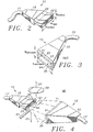
- the radiated energy beam an electron beam according to the preferred embodiment of the present invention, is directed into that portion of the flowing gas 11 proximate the converging-diverging nozzle 10, so as to enhance the efficiency of the present invention.
- Figure 4 illustrates the relative positions of the electron beam 23 and the flowing gas 11 in perspective.
- a portion of the extreme ultra-violet light 27 whose emission is stimulated from the flowing gas 11 by the radiated energy beam 23 is collected and focused by collecting and focusing optics 29, which direct the extreme ultra-violet light onto a work piece, i.e., an integrated circuit component being fabricated, as desired.
- a vacuum pump preferably that vacuum pump 36 utilized to evacuate the vacuum chamber 40 within which the gas 11 flows and within which the photolithographic process is performed, evacuates a substantial portion of the gas 11 which is not captured by the diffuser 12 and provides that gas 11 back to the converging-diverging nozzle 10, preferably via the compressor 14 and heat exchanger 16, so as to facilitate recycling thereof.
- a gas preferably a noble gas such as argon, helium, or xenon, or a combination thereof, flows at a supersonic velocity from the converging-diverging nozzle 18 when a pressurized supply thereof is provided to the converging-diverging nozzle 18 via gas conduit 17.
- a gas preferably a noble gas such as argon, helium, or xenon, or a combination thereof, flows at a supersonic velocity from the converging-diverging nozzle 18 when a pressurized supply thereof is provided to the converging-diverging nozzle 18 via gas conduit 17.
- Sufficient pressure is provided by compressor 14 to achieve the desired gas flow speed.
- a radiated energy beam preferably an electron beam, is directed through the supersonic gas flow 11 at a position which minimizes the transmission of the resulting extreme ultra-violet light through the gas 11, thereby mitigating undesirable absorption thereof.
- a substantial portion of the flowing gas 11 is captured by the diffuser 12 and recycled.
- a substantial portion of the gas not captured by the diffuser 12 is evacuated from the vacuum chamber 40 via vacuum pump 36 and recycled.
- At least a portion of the extreme ultra-violet light 27 emitted due to the interaction of the radiated energy beam 23 with the supersonic gas 11 is collected and focused by collecting and focusing optics 29 so as to facilitate photolithography therewith.
- contamination of the collecting and focusing optics 29, as well as any other sensitive surfaces within the vacuum chamber 40 is mitigated.
- Such contamination is mitigated since supersonic flow of the gas 11 tends to force all of the gas particles, i.e., molecules, atoms, ions, electrons, etc., into the diffuser 12, thereby substantially mitigating the amount of such particles floating freely within the vacuum chamber 40 and capable of coming into contact with such sensitive items.
- the present invention takes advantage of the gas dynamic properties of the supersonic jet to direct any debris generated during the plasma formation into the diffuser, and thus away from the collection and focusing optics 29, as well as the rest of the photolithography system.
- the efficiency of the present invention is enhanced by minimizing the amount of gas 11 through which the generated extreme ultra-violet light 27 must pass.
- extreme ultra-violet light is readily absorbed (and thus attenuated) by the noble gasses from which its emission is stimulated.
- the high density gas region is confined to nearly the same volume as that occupied by the radiated energy beam.
- extreme ultra-violet light generated thereby is not required to travel through a substantial portion of the high density gas after leaving the area where stimulated emission occurs.
- the high aspect ratio configuration of the converging-diverging nozzle tends to maximize the volume of flowing gas available for interaction with the radiated energy beam, while simultaneously minimizing the volume of flowing gas which attenuates the stimulated extreme ultra-violet light.
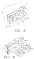
- Each generally concentric knife edge 33, 35 of Figure 3 preferably comprises a body 37 and a bevel 39.
- the converging-diverging nozzle is optionally configured as a cap 10a which is specifically sized and shaped to fit a standard pulse generator.
- the cap 10a comprises a body 50 which is sized to be received within the exit orifice of a pulse generator and a flange 52 which functions as a stop to limit insertion of the body 50 into the exit orifice.
- a rectangular boss 54 has a rectangular opening 56 formed therein.
- the converging-diverging bore 58 of the nozzle is formed in a continuous or co-extensive manner in the body 50, flange 52, and boss 54. Such construction facilitates easy removal and replacement of the converging-diverging nozzle 10a, particularly when a standard pulse generator is utilized.
- the nozzle comprises a converging region 60 which decreases to form a neck 62 and then increases in cross-sectional area to form the diverging region 64 thereof.
- the exit plane 66 is that plane of the nozzle flush with the end thereof, i.e., the outer opening thereof.
- the diffuser tapers or converges from the entry plane 70 to define a converging portion 72 thereof.
- a neck 74 is formed and the diffuser may then optionally diverge or increase in cross-sectional area so as to form a diverging portion 76.
- the velocity of the flowing gas 11 decreases within the converging portion 72, while the pressure thereof simultaneously increases.
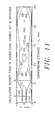
- FIG. 11 the calculated density field for a xenon extreme ultra-violet light source jet and diffuser is shown.
- Gas 11a from within the converging-diverging nozzle exits therefrom at the exit plane 66 to form gas jet 11b.
- the gas jet 11b enters the diffuser at the entry plane 70 thereof.
- first oblique shocks 80 are formed due to the knife edge(s) 31 defined by the opening 30 of the diffuser 12.
- the oblique shocks 80 interact to form perpendicular shock 82 downstream therefrom.
- Second oblique shocks 84 are formed as the flowing gas interacts with the internal walls of the diffuser.
- the second oblique shocks 84 interact with one another so as to form perpendicular shock 86.
- Third oblique shocks 88 are formed in a similar manner downstream from the second oblique shocks 84.
- each shock defines a high pressure region within which the flowing gas slows.
- a plurality of knife edges may be utilized to form shocks so as to effect slowing of the gas flow and increasing the pressure thereof.
- the exemplary method and apparatus for producing extreme ultra-violet light described herein and shown in the drawings represents only a presently preferred embodiment of the invention. Indeed, various modifications and additions may be made to such embodiment without departing from the spirit and scope of the invention. For example, various sizes, shapes, cross-sectional configurations, etc. of the nozzle and diffuser are contemplated. It must further be appreciated that various different configurations of the radiated energy beam,, other than circular as shown, may be utilized. For example, the radiated energy beam 23 may alternatively be elliptical, square, rectangular, triangular, etc.
- the radiated energy beam 23 be comparable in cross-sectional area to that portion of the flowing gas 11 proximate the converging-diverging nozzle 10, so as to minimize the amount of gas 11 through which stimulated extreme ultra-violet light 27 must flow.
- the method and apparatus for producing extreme ultra-violet light according to the present invention may be utilized in a variety of different applications, and is not limited to use in photolithographic applications. Further, it must also be appreciated that the general method and apparatus of the present invention may alternatively be utilized to produce wavelengths of electromagnetic radiation other than extreme ultra-violet, and thus is not limited to the production of extreme ultra-violet light.
Landscapes
- Engineering & Computer Science (AREA)
- Physics & Mathematics (AREA)
- Plasma & Fusion (AREA)
- Epidemiology (AREA)
- Public Health (AREA)
- General Physics & Mathematics (AREA)
- Chemical & Material Sciences (AREA)
- Optics & Photonics (AREA)
- Nanotechnology (AREA)
- Life Sciences & Earth Sciences (AREA)
- Atmospheric Sciences (AREA)
- Health & Medical Sciences (AREA)
- Crystallography & Structural Chemistry (AREA)
- Mathematical Physics (AREA)
- Environmental & Geological Engineering (AREA)
- Theoretical Computer Science (AREA)
- Exposure And Positioning Against Photoresist Photosensitive Materials (AREA)
Applications Claiming Priority (3)
| Application Number | Priority Date | Filing Date | Title |
|---|---|---|---|
| US08/794,802 US6133577A (en) | 1997-02-04 | 1997-02-04 | Method and apparatus for producing extreme ultra-violet light for use in photolithography |
| US794802 | 1997-02-04 | ||
| PCT/US1997/023915 WO1998034234A1 (en) | 1997-02-04 | 1997-12-23 | Method and apparatus for producing extreme ultra-violet light for use in photolithography |
Publications (3)
| Publication Number | Publication Date |
|---|---|
| EP1016092A1 EP1016092A1 (en) | 2000-07-05 |
| EP1016092A4 EP1016092A4 (en) | 2001-11-14 |
| EP1016092B1 true EP1016092B1 (en) | 2004-06-16 |
Family
ID=25163724
Family Applications (1)
| Application Number | Title | Priority Date | Filing Date |
|---|---|---|---|
| EP97954243A Expired - Lifetime EP1016092B1 (en) | 1997-02-04 | 1997-12-23 | Method and apparatus for producing extreme ultra-violet light for use in photolithography |
Country Status (5)
| Country | Link |
|---|---|
| US (1) | US6133577A (enExample) |
| EP (1) | EP1016092B1 (enExample) |
| JP (1) | JP2001511311A (enExample) |
| DE (1) | DE69729588T2 (enExample) |
| WO (1) | WO1998034234A1 (enExample) |
Families Citing this family (30)
| Publication number | Priority date | Publication date | Assignee | Title |
|---|---|---|---|---|
| US6194733B1 (en) | 1998-04-03 | 2001-02-27 | Advanced Energy Systems, Inc. | Method and apparatus for adjustably supporting a light source for use in photolithography |
| EP1068019A1 (en) * | 1998-04-03 | 2001-01-17 | Advanced Energy Systems, Inc. | Energy emission system for photolithography |
| AU3469999A (en) * | 1998-04-03 | 1999-10-25 | Advanced Energy Systems, Inc. | Fluid nozzle system, energy emission system for photolithography and its method of manufacture |
| AU3466899A (en) * | 1998-04-03 | 1999-10-25 | Advanced Energy Systems, Inc. | Diffuser system and energy emission system for photolithography |
| US6105885A (en) | 1998-04-03 | 2000-08-22 | Advanced Energy Systems, Inc. | Fluid nozzle system and method in an emitted energy system for photolithography |
| US6065203A (en) * | 1998-04-03 | 2000-05-23 | Advanced Energy Systems, Inc. | Method of manufacturing very small diameter deep passages |
| US6190835B1 (en) * | 1999-05-06 | 2001-02-20 | Advanced Energy Systems, Inc. | System and method for providing a lithographic light source for a semiconductor manufacturing process |
| WO2001007967A1 (en) | 1999-07-22 | 2001-02-01 | Corning Incorporated | Extreme ultraviolet soft x-ray projection lithographic method and mask devices |
| US6304630B1 (en) * | 1999-12-24 | 2001-10-16 | U.S. Philips Corporation | Method of generating EUV radiation, method of manufacturing a device by means of said radiation, EUV radiation source unit, and lithographic projection apparatus provided with such a radiation source unit |
| WO2002019781A1 (en) * | 2000-08-31 | 2002-03-07 | Powerlase Limited | Electromagnetic radiation generation using a laser produced plasma |
| US6776006B2 (en) | 2000-10-13 | 2004-08-17 | Corning Incorporated | Method to avoid striae in EUV lithography mirrors |
| GB0111204D0 (en) * | 2001-05-08 | 2001-06-27 | Mertek Ltd | High flux,high energy photon source |
| US6744851B2 (en) | 2002-05-31 | 2004-06-01 | Northrop Grumman Corporation | Linear filament array sheet for EUV production |
| US6770895B2 (en) * | 2002-11-21 | 2004-08-03 | Asml Holding N.V. | Method and apparatus for isolating light source gas from main chamber gas in a lithography tool |
| DE10306668B4 (de) * | 2003-02-13 | 2009-12-10 | Xtreme Technologies Gmbh | Anordnung zur Erzeugung von intensiver kurzwelliger Strahlung auf Basis eines Plasmas |
| US6919573B2 (en) * | 2003-03-20 | 2005-07-19 | Asml Holding N.V | Method and apparatus for recycling gases used in a lithography tool |
| DE10326279A1 (de) * | 2003-06-11 | 2005-01-05 | MAX-PLANCK-Gesellschaft zur Förderung der Wissenschaften e.V. | Plasma-basierte Erzeugung von Röntgenstrahlung mit einem schichtförmigen Targetmaterial |
| US7154931B2 (en) | 2004-06-22 | 2006-12-26 | Ksy Corporation | Laser with Brayton cycle outlet pump |
| US7469710B1 (en) | 2004-06-22 | 2008-12-30 | Ksy Corporation | Supersonic diffuser |
| US7655925B2 (en) * | 2007-08-31 | 2010-02-02 | Cymer, Inc. | Gas management system for a laser-produced-plasma EUV light source |
| JP5559562B2 (ja) * | 2009-02-12 | 2014-07-23 | ギガフォトン株式会社 | 極端紫外光光源装置 |
| JP5578482B2 (ja) * | 2009-09-01 | 2014-08-27 | 株式会社Ihi | Lpp方式のeuv光源とその発生方法 |
| JP5578483B2 (ja) * | 2009-09-01 | 2014-08-27 | 株式会社Ihi | Lpp方式のeuv光源とその発生方法 |
| US8648536B2 (en) | 2009-09-01 | 2014-02-11 | Ihi Corporation | Plasma light source |
| JP2011054376A (ja) * | 2009-09-01 | 2011-03-17 | Ihi Corp | Lpp方式のeuv光源とその発生方法 |
| WO2013156041A1 (en) * | 2012-04-18 | 2013-10-24 | Carl Zeiss Smt Gmbh | A microlithographic apparatus and a method of changing an optical wavefront in an objective of such an apparatus |
| US20140166051A1 (en) * | 2012-12-17 | 2014-06-19 | Kla-Tencor Corporation | Apparatus, system, and method for separating gases and mitigating debris in a controlled pressure environment |
| US9585236B2 (en) | 2013-05-03 | 2017-02-28 | Media Lario Srl | Sn vapor EUV LLP source system for EUV lithography |
| WO2017030948A1 (en) | 2015-08-19 | 2017-02-23 | The Regents Of The University Of California | Shock injector for low-laser energy electron injection in a laser plasma accelerator |
| WO2025153242A1 (en) * | 2024-01-17 | 2025-07-24 | Asml Netherlands B.V. | Method and device for tuning flow velocity profile |
Family Cites Families (37)
| Publication number | Priority date | Publication date | Assignee | Title |
|---|---|---|---|---|
| NL292326A (enExample) * | 1962-05-09 | |||
| US3686528A (en) * | 1969-12-05 | 1972-08-22 | Tamarack Scient Co Inc | Jet pinched plasma arc lamp and method of forming plasma arc |
| DE2020055A1 (de) * | 1970-04-24 | 1971-12-02 | Mueller Ernst Kg | Verfahren und Vorrichtung zum UEberziehen von Gegenstaenden mit pulverfoermigen Stoffen |
| US3904985A (en) * | 1971-12-21 | 1975-09-09 | Us Energy | Explosive laser |
| US3876149A (en) * | 1973-04-26 | 1975-04-08 | William J Futerko | Method of forming a torch tip and torch tips |
| US3972474A (en) * | 1974-11-01 | 1976-08-03 | A. B. Dick Company | Miniature ink jet nozzle |
| US4161280A (en) * | 1977-10-13 | 1979-07-17 | State Of Connecticut | Method and apparatus for dispensing a deicer liquid |
| US4178078A (en) * | 1978-09-19 | 1979-12-11 | United Technologies Corporation | Aerodynamic window |
| US4455470A (en) * | 1981-08-14 | 1984-06-19 | The Perkin-Elmer Corporation | Plasma spray gun nozzle and coolant deionizer |
| US4408338A (en) * | 1981-12-31 | 1983-10-04 | International Business Machines Corporation | Pulsed electromagnetic radiation source having a barrier for discharged debris |
| US4584479A (en) * | 1982-10-19 | 1986-04-22 | Varian Associates, Inc. | Envelope apparatus for localized vacuum processing |
| US4607167A (en) * | 1982-10-19 | 1986-08-19 | Varian Associates, Inc. | Charged particle beam lithography machine incorporating localized vacuum envelope |
| US4549082A (en) * | 1983-04-19 | 1985-10-22 | Mcmillan Michael R | Synthetic plasma ion source |
| US4560880A (en) * | 1983-09-19 | 1985-12-24 | Varian Associates, Inc. | Apparatus for positioning a workpiece in a localized vacuum processing system |
| US4577122A (en) * | 1983-12-28 | 1986-03-18 | The Regents Of The University Of California | Method and apparatus for generation of coherent VUV and XUV radiation |
| US4692934A (en) * | 1984-11-08 | 1987-09-08 | Hampshire Instruments | X-ray lithography system |
| US4820927A (en) * | 1985-06-28 | 1989-04-11 | Control Data Corporation | Electron beam source employing a photo-emitter cathode |
| LU86322A1 (fr) * | 1986-02-25 | 1987-09-10 | Arbed | Lance de soufflage d'oxygene |
| US5204506A (en) * | 1987-12-07 | 1993-04-20 | The Regents Of The University Of California | Plasma pinch surface treating apparatus and method of using same |
| US4830280A (en) * | 1988-03-21 | 1989-05-16 | Yankoff Gerald K | Nozzle |
| JPH0637521Y2 (ja) * | 1988-10-05 | 1994-09-28 | 高橋 柾弘 | マイクロ波励起による紫外線発生装置 |
| US5298835A (en) * | 1988-07-21 | 1994-03-29 | Electro-Plasma, Inc. | Modular segmented cathode plasma generator |
| US5012853A (en) * | 1988-09-20 | 1991-05-07 | Sundstrand Corporation | Process for making articles with smooth complex internal geometries |
| US4982067A (en) * | 1988-11-04 | 1991-01-01 | Marantz Daniel Richard | Plasma generating apparatus and method |
| US5012105A (en) * | 1989-02-02 | 1991-04-30 | Nippon Seiko Kabushiki Kaisha | Multiple-imaging charged particle-beam exposure system |
| US5103102A (en) * | 1989-02-24 | 1992-04-07 | Micrion Corporation | Localized vacuum apparatus and method |
| US4954715A (en) * | 1989-06-26 | 1990-09-04 | Zoeld Tibor | Method and apparatus for an optimized multiparameter flow-through particle and cell analyzer |
| US4980563A (en) * | 1990-01-09 | 1990-12-25 | United States Department Of Energy | VUV lithography |
| EP0463815B1 (en) * | 1990-06-22 | 1995-09-27 | Kabushiki Kaisha Toshiba | Vacuum ultraviolet light source |
| JP2619565B2 (ja) * | 1990-11-05 | 1997-06-11 | 株式会社日立製作所 | 電子ビーム描画装置 |
| WO1994013010A1 (en) * | 1991-04-15 | 1994-06-09 | Fei Company | Process of shaping features of semiconductor devices |
| US5175929A (en) * | 1992-03-04 | 1993-01-05 | General Electric Company | Method for producing articles by chemical vapor deposition |
| US5643801A (en) * | 1992-11-06 | 1997-07-01 | Semiconductor Energy Laboratory Co., Ltd. | Laser processing method and alignment |
| US5577091A (en) * | 1994-04-01 | 1996-11-19 | University Of Central Florida | Water laser plasma x-ray point sources |
| US5499282A (en) * | 1994-05-02 | 1996-03-12 | University Of Central Florida | Efficient narrow spectral width soft-X-ray discharge sources |
| US5577092A (en) * | 1995-01-25 | 1996-11-19 | Kublak; Glenn D. | Cluster beam targets for laser plasma extreme ultraviolet and soft x-ray sources |
| US5644137A (en) * | 1996-03-04 | 1997-07-01 | Waggener; Herbert A. | Stabilizing support mechanism for electron beam apparatus |
-
1997
- 1997-02-04 US US08/794,802 patent/US6133577A/en not_active Expired - Fee Related
- 1997-12-23 DE DE69729588T patent/DE69729588T2/de not_active Expired - Fee Related
- 1997-12-23 EP EP97954243A patent/EP1016092B1/en not_active Expired - Lifetime
- 1997-12-23 JP JP53287998A patent/JP2001511311A/ja not_active Ceased
- 1997-12-23 WO PCT/US1997/023915 patent/WO1998034234A1/en not_active Ceased
Also Published As
| Publication number | Publication date |
|---|---|
| EP1016092A1 (en) | 2000-07-05 |
| JP2001511311A (ja) | 2001-08-07 |
| WO1998034234A1 (en) | 1998-08-06 |
| DE69729588D1 (de) | 2004-07-22 |
| DE69729588T2 (de) | 2005-06-23 |
| US6133577A (en) | 2000-10-17 |
| EP1016092A4 (en) | 2001-11-14 |
Similar Documents
| Publication | Publication Date | Title |
|---|---|---|
| EP1016092B1 (en) | Method and apparatus for producing extreme ultra-violet light for use in photolithography | |
| US6552350B2 (en) | System and method for providing a lithographic light source for a semiconductor manufacturing process | |
| JP5448775B2 (ja) | 極端紫外光源装置 | |
| TWI576013B (zh) | 雷射生成電漿光源中緩衝氣流穩定化的系統與方法 | |
| JP2004533704A (ja) | 特にリソグラフィのための極短紫外の光を生成するための方法及び装置 | |
| US6714624B2 (en) | Discharge source with gas curtain for protecting optics from particles | |
| JP4690686B2 (ja) | Euv源 | |
| US20220365451A1 (en) | Apparatus And A Method Of Forming A Particle Shield | |
| JP4995379B2 (ja) | 光源装置及びそれを用いた露光装置 | |
| JP2005108834A5 (enExample) | ||
| US6194733B1 (en) | Method and apparatus for adjustably supporting a light source for use in photolithography | |
| US6353232B2 (en) | Holder assembly system and method in an emitted energy system for photolithography | |
| JP2004507873A5 (enExample) | ||
| JP2004507873A (ja) | レーザ発生されたプラズマを使用する電磁放射発生 | |
| WO1999051357A1 (en) | Energy emission system for photolithography | |
| US6105885A (en) | Fluid nozzle system and method in an emitted energy system for photolithography | |
| JP3433151B2 (ja) | レーザプラズマx線源 | |
| TWI778641B (zh) | 微影系統和在微影系統中產生層流的裝置 | |
| JP2002510874A (ja) | フォトリソグラフィのための流体ノズルシステム、エネルギー放射システム及びその製造方法 | |
| Fornaciari et al. | Discharge source with gas curtain for protecting optics from particles | |
| WO1999051355A1 (en) | Diffuser system and energy emission system for photolithography |
Legal Events
| Date | Code | Title | Description |
|---|---|---|---|
| PUAI | Public reference made under article 153(3) epc to a published international application that has entered the european phase |
Free format text: ORIGINAL CODE: 0009012 |
|
| 17P | Request for examination filed |
Effective date: 19990903 |
|
| AK | Designated contracting states |
Kind code of ref document: A1 Designated state(s): DE FR GB IT NL |
|
| A4 | Supplementary search report drawn up and despatched |
Effective date: 20011004 |
|
| AK | Designated contracting states |
Kind code of ref document: A4 Designated state(s): DE FR GB IT NL |
|
| RIC1 | Information provided on ipc code assigned before grant |
Free format text: 7G 21G 4/00 A, 7G 21G 5/00 B, 7G 01J 1/00 B, 7H 05G 2/00 B |
|
| 17Q | First examination report despatched |
Effective date: 20020227 |
|
| GRAP | Despatch of communication of intention to grant a patent |
Free format text: ORIGINAL CODE: EPIDOSNIGR1 |
|
| GRAS | Grant fee paid |
Free format text: ORIGINAL CODE: EPIDOSNIGR3 |
|
| GRAA | (expected) grant |
Free format text: ORIGINAL CODE: 0009210 |
|
| AK | Designated contracting states |
Kind code of ref document: B1 Designated state(s): DE FR GB IT NL |
|
| REG | Reference to a national code |
Ref country code: GB Ref legal event code: FG4D |
|
| REF | Corresponds to: |
Ref document number: 69729588 Country of ref document: DE Date of ref document: 20040722 Kind code of ref document: P |
|
| ET | Fr: translation filed | ||
| PLBE | No opposition filed within time limit |
Free format text: ORIGINAL CODE: 0009261 |
|
| STAA | Information on the status of an ep patent application or granted ep patent |
Free format text: STATUS: NO OPPOSITION FILED WITHIN TIME LIMIT |
|
| 26N | No opposition filed |
Effective date: 20050317 |
|
| PGFP | Annual fee paid to national office [announced via postgrant information from national office to epo] |
Ref country code: GB Payment date: 20051221 Year of fee payment: 9 |
|
| PGFP | Annual fee paid to national office [announced via postgrant information from national office to epo] |
Ref country code: FR Payment date: 20051222 Year of fee payment: 9 |
|
| PGFP | Annual fee paid to national office [announced via postgrant information from national office to epo] |
Ref country code: NL Payment date: 20051227 Year of fee payment: 9 |
|
| PGFP | Annual fee paid to national office [announced via postgrant information from national office to epo] |
Ref country code: DE Payment date: 20061229 Year of fee payment: 10 |
|
| PGFP | Annual fee paid to national office [announced via postgrant information from national office to epo] |
Ref country code: IT Payment date: 20061231 Year of fee payment: 10 |
|
| PG25 | Lapsed in a contracting state [announced via postgrant information from national office to epo] |
Ref country code: NL Free format text: LAPSE BECAUSE OF NON-PAYMENT OF DUE FEES Effective date: 20070701 |
|
| GBPC | Gb: european patent ceased through non-payment of renewal fee |
Effective date: 20061223 |
|
| NLV4 | Nl: lapsed or anulled due to non-payment of the annual fee |
Effective date: 20070701 |
|
| REG | Reference to a national code |
Ref country code: FR Ref legal event code: ST Effective date: 20070831 |
|
| PG25 | Lapsed in a contracting state [announced via postgrant information from national office to epo] |
Ref country code: GB Free format text: LAPSE BECAUSE OF NON-PAYMENT OF DUE FEES Effective date: 20061223 |
|
| PG25 | Lapsed in a contracting state [announced via postgrant information from national office to epo] |
Ref country code: FR Free format text: LAPSE BECAUSE OF NON-PAYMENT OF DUE FEES Effective date: 20070102 |
|
| PG25 | Lapsed in a contracting state [announced via postgrant information from national office to epo] |
Ref country code: DE Free format text: LAPSE BECAUSE OF NON-PAYMENT OF DUE FEES Effective date: 20080701 |
|
| PG25 | Lapsed in a contracting state [announced via postgrant information from national office to epo] |
Ref country code: IT Free format text: LAPSE BECAUSE OF NON-PAYMENT OF DUE FEES Effective date: 20071223 |