EP1014404B1 - Kassettenlaufwerk mit beleuchtbaren Laufwerkstasten - Google Patents
Kassettenlaufwerk mit beleuchtbaren Laufwerkstasten Download PDFInfo
- Publication number
- EP1014404B1 EP1014404B1 EP99123264A EP99123264A EP1014404B1 EP 1014404 B1 EP1014404 B1 EP 1014404B1 EP 99123264 A EP99123264 A EP 99123264A EP 99123264 A EP99123264 A EP 99123264A EP 1014404 B1 EP1014404 B1 EP 1014404B1
- Authority
- EP
- European Patent Office
- Prior art keywords
- drive
- buttons
- cassette
- drive according
- cassette drive
- Prior art date
- Legal status (The legal status is an assumption and is not a legal conclusion. Google has not performed a legal analysis and makes no representation as to the accuracy of the status listed.)
- Expired - Lifetime
Links
- 239000004020 conductor Substances 0.000 claims description 7
- 230000008878 coupling Effects 0.000 description 1
- 238000010168 coupling process Methods 0.000 description 1
- 238000005859 coupling reaction Methods 0.000 description 1
- 238000005286 illumination Methods 0.000 description 1
- 238000009434 installation Methods 0.000 description 1
Images
Classifications
-
- H—ELECTRICITY
- H01—ELECTRIC ELEMENTS
- H01H—ELECTRIC SWITCHES; RELAYS; SELECTORS; EMERGENCY PROTECTIVE DEVICES
- H01H13/00—Switches having rectilinearly-movable operating part or parts adapted for pushing or pulling in one direction only, e.g. push-button switch
- H01H13/02—Details
- H01H13/023—Light-emitting indicators
Definitions
- the invention relates to a cassette drive, for example for music cassettes, in which a shift linkage can be actuated with illuminated drive buttons. It is known from the prior art to have such drive buttons on the Put on shift linkage and the lighting of the drive buttons through Coupling of light beams via light-guiding elements in the two end positions to implement the switch. The disadvantage here is that the Switches can be illuminated unevenly depending on their position.
- the object of the invention is therefore to provide a cassette drive in which a shift linkage can be actuated with illuminated drive buttons, the Drive buttons are evenly illuminated.
- the drive buttons pot-like or with a recess, each with a radiolucent bottom are formed, each in the pot opening or in the recess a light source is arranged, which can be supplied with voltage via flexible conductors is and in that the drive buttons mechanically from the shift linkage are uncouplable.
- the drive button By arranging the light source in the pot opening or in the recess the drive button can be illuminated evenly regardless of the position of the drive button.
- decoupling from Drive button and shift linkage it is possible to use the drive buttons in the housing with a small tolerance and thus the flexible conductors for power supply the light sources inside the drive button.
- a light-emitting diode as a light source has a particularly long lifespan little energy and therefore does not heat the drive buttons unnecessarily on.
- the decoupling of the drive button from the shift linkage is easy Realize that when you press the drive button on the Drive button applied force directly or through an adapter on the Transmits shift linkage.
- Elastic elements can act on these webs and thus the drive buttons simply hold in a basic position or after pressing the drive buttons bring them back to the basic position.
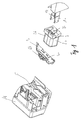
- FIG. 1 shows shift rods 1a, 1b of the shift linkage, which is otherwise not shown, Drive buttons 2a, 2b, a lighting device 3 and a Front housing part 4 shown.
- the shift rods 1a, 1b are with the cassette drive, not shown connected.
- the drive buttons 2a, 2b are directly on the ends shown the shift rods 1a, 1b placed and protrude through an opening 5 of the Front housing part 4 to the outside.
- the lighting device 3 is in the front housing part 4 arranged below the opening 5 such that the light of LEDs 6a, 6b on the underside of the drive buttons 2a, 2b in this is coupled in and via prismatic, translucent portions 7a, 7b Drive buttons 2a, 2b directed to the front of the drive buttons 2a, 2b becomes.
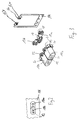
- drive buttons 10a, 10b protrude from a housing 11.
- the drive buttons 10a, 10b are so cup-shaped that the symbols 12 located on their base are shone through by light can while the remnants of the drive buttons visible outside the case 10a, 10b are designed to be opaque.
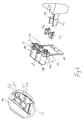
- FIG. 3 shows a possibility of lighting according to the invention
- Drive buttons 10a, 10b are clamping pieces 13a, 13b and a flexible film 14 shown.
- Two light-emitting diodes 15a, 15b are on the flexible film 14 Illumination one of the drive buttons 10a, 10b attached.
- the flexible Film 14 has recesses 16 in the webs 17 of the clamping pieces 13a, 13b protrude and position them.
- the clamping pieces 13a, 13b are with the inserted or glued-on flexible film in the drive buttons 10a, 10b engaged that the locking lugs 18 of the clamping pieces 13a, 13b in the Engage catch 19 of drive buttons 10a, 10b.
- the side faces of the drive buttons 10a, 10b are partially designed as guide surfaces 20 which webs 21, 22 are arranged.
- the shift rods 1a, 1b, intermediate pieces 23a, 23b and part of the housing 11 are shown.
- the housing 11 has guide surfaces 25 and grooves 26 arranged therein, 27 on.
- the drive buttons 10a, 10b are actuated, they slide with their Guide surfaces 20 on the guide surfaces 25 of the housing 11 while the webs 21, 22 are guided in the grooves 26, 27. Even those between the adjacent drive buttons 10a, 10b are on their surfaces entire length formed as guide surfaces. So overall one excellent leadership and the risk of jamming or jamming Noise caused by vibration of the drive buttons 10a, 10b excluded.
- the flexible film 14 has electrical conductor tracks, not shown, which supply the LEDs 15a, 15b with current.
- the flexible film 14 is with the housing 11 mechanically and its conductor tracks are not shown Connections of the housing electrically connected. Elastic not shown Elements engage the webs 22 and hold the drive buttons 10a, 10b without any other external force in their basic position.
- the contact surfaces of the intermediate pieces 23a, 23b and the clamping pieces 13a, 13b to each other are designed so that when pressing the respective Drive button 10a, 10b this somewhat in the direction of the other drive button 10b, 10a is pressed and thus the drive button 10a, 10b the side surface of each other drive button 10b, 10a slides, if only one of the drive buttons 10a, 10b is pressed.
Landscapes
- Push-Button Switches (AREA)
- Mechanical Control Devices (AREA)
Description
- Figur 1
- eine perspektivische Ansicht von Einzelteilen eines Kassettenlaufwerks mit beleuchtbaren Laufwerkstasten nach dem Stand der Technik.
- Figur 2
- eine Aufsicht auf ein Ausführungsbeispiel zweier erfindungsgemäßer Laufwerkstasten und ein Teil eines Gehäuses eines Kassettenlaufwerks.
- Figur 3
- die perspektivische Ansicht eines erfindungsgemäßen Ausführungsbeispiels zweier Laufwerkstasten, zweier Klemmstücke und einer flexiblen Folie mit darauf angebrachten Leuchtdioden.
- Figur 4
- die perspektivische Ansicht der zusammengesetzten Bauteile aus Figur 3 im Zusammenwirken mit dem Gehäuse und dem Schaltgestänge.
Claims (12)
- Kassettenlaufwerk, bei dem mit beleuchtbaren Laufwerkstasten ein Schaltgestänge betätigbar ist, dadurch gekennzeichnet, daß die Laufwerkstasten (10a, 10b) topfartig oder mit einer Ausnehmung mit jeweils einem durchleuchtbaren Boden ausgebildet sind, wobei in der Topföffnung oder in der Ausnehmung jeweils eine Lichtquelle (15a, 15b) angeordnet ist, die über flexible Leiter mit Spannung versorgbar ist, daß die Laufwerkstasten (10a, 10b) mechanisch von dem Schaltgestänge entkoppelbar sind.
- Kassettenlaufwerk nach Anspruch 1, dadurch gekennzeichnet, daß Leuchtdioden (15a, 15b) als Lichtquelle verwendet werden.
- Kassettenlaufwerk nach Anspruch 2, dadurch gekennzeichnet, daß die Leuchtdioden (15a, 15b) auf einer flexiblen Folie (14) aufgebracht sind.
- Kassettenlaufwerk nach Anspruch 3, dadurch gekennzeichnet, daß auf der flexiblen Folie (14) flexible Leiter angebracht sind.
- Kassettenlaufwerk nach Anspruch 3 oder 4, dadurch gekennzeichnet, daß die flexible Folie (14) von einem Klemmstück (13a, 13b) in der Laufwerkstaste (10a, 10b) gehalten wird.
- Kassettenlaufwerk nach Anspruch 5, dadurch gekennzeichnet, daß die flexible Folie (14) Ausnehmungen (16) aufweist, in die Stege (17) des Klemmstücks (13a, 13b) greifen.
- Kassettenlaufwerk nach einem der vorstehenden Ansprüche, dadurch gekennzeichnet, daß die Laufwerkstasten (10a, 10b) samt Klemmstück (13a, 13b) derart ausgestaltet sind, daß sie die beim Betätigen der Laufwerkstasten (10a, 10b) aufgebrachte Kraft direkt oder über Zwischenstücke (23a, 23b) auf das Schaltgestänge übertragen.
- Kassettenlaufwerk nach Anspruch 7, dadurch gekennzeichnet, daß das in der Laufwerkstaste (10a, 10b) befindliche Klemmstück (13a, 13b) beim Druck auf die Laufwerkstaste das auf einer Schaltstange (1a, 1b) angeordnete Zwischenstück (23a, 23b) berührt und so eine Betätigungskraft auf das Schaltgestänge übertragbar ist.
- Kassettenlaufwerk nach einem der vorstehenden Ansprüche, dadurch gekennzeichnet, daß die Laufwerkstasten (10a, 10b) Führungsflächen (20) aufweisen, die mit Führungsflächen (25) des Gehäuses oder der benachbarten Laufwerkstaste (10b, 10a) zusammenwirken.
- Kassettenlaufwerk nach einem der vorstehenden Ansprüche, insbesondere nach Anspruch 9, dadurch gekennzeichnet, daß die Laufwerkstasten (10a, 10b) Stege (21, 22) aufweisen, die in Nuten (26, 27) des Gehäuses (11) geführt werden.
- Kassettenlaufwerk nach Anspruch 10, dadurch gekennzeichnet, daß an den Stegen (22) elastische Elemente angreifen, die die Laufwerkstasten (10a, 10b) in eine Grundposition entfernt von den Schaltstangen (1a, 1b) beziehungsweise den Zwischenstücken (23a, 23b) bringen beziehungsweise halten, wenn die Laufwerkstasten (10a, 10b) nicht betätigt werden.
- Kassettenlaufwerk nach Anspruch 11, dadurch gekennzeichnet, daß die elastischen Elemente als Federn ausgestaltet sind.
Applications Claiming Priority (2)
| Application Number | Priority Date | Filing Date | Title |
|---|---|---|---|
| DE19857864 | 1998-12-15 | ||
| DE19857864A DE19857864A1 (de) | 1998-12-15 | 1998-12-15 | Kassettenlaufwerk mit beleuchtbaren Laufwerkstasten |
Publications (2)
| Publication Number | Publication Date |
|---|---|
| EP1014404A1 EP1014404A1 (de) | 2000-06-28 |
| EP1014404B1 true EP1014404B1 (de) | 2003-05-21 |
Family
ID=7891172
Family Applications (1)
| Application Number | Title | Priority Date | Filing Date |
|---|---|---|---|
| EP99123264A Expired - Lifetime EP1014404B1 (de) | 1998-12-15 | 1999-11-29 | Kassettenlaufwerk mit beleuchtbaren Laufwerkstasten |
Country Status (2)
| Country | Link |
|---|---|
| EP (1) | EP1014404B1 (de) |
| DE (2) | DE19857864A1 (de) |
Family Cites Families (4)
| Publication number | Priority date | Publication date | Assignee | Title |
|---|---|---|---|---|
| DE2933983C2 (de) * | 1979-08-22 | 1984-03-22 | Siemens AG, 1000 Berlin und 8000 München | Taste mit Leuchtanzeige für Tastaturen in Büro- und Fernschreibmaschinen |
| DD298178A5 (de) * | 1989-09-19 | 1992-02-06 | �K�K�K�K@�������`������@�����������@�������k�� | Leuchttastschalter |
| ATE149735T1 (de) * | 1991-12-24 | 1997-03-15 | Inventio Ag | Befehls- und meldegerät |
| US5367135A (en) * | 1993-10-26 | 1994-11-22 | Chrysler Corporation | Push button construction for player control |
-
1998
- 1998-12-15 DE DE19857864A patent/DE19857864A1/de not_active Withdrawn
-
1999
- 1999-11-29 EP EP99123264A patent/EP1014404B1/de not_active Expired - Lifetime
- 1999-11-29 DE DE59905637T patent/DE59905637D1/de not_active Expired - Lifetime
Also Published As
| Publication number | Publication date |
|---|---|
| DE59905637D1 (de) | 2003-06-26 |
| DE19857864A1 (de) | 2000-06-29 |
| EP1014404A1 (de) | 2000-06-28 |
Similar Documents
| Publication | Publication Date | Title |
|---|---|---|
| EP0377116B1 (de) | Tastschalter | |
| DE2730763A1 (de) | Flacher leuchtdrucktastenschalter | |
| DE4242100B4 (de) | Elektrisches Schaltgerät | |
| EP0699338B1 (de) | Elektrischer drucktastenschalter | |
| EP0024620B1 (de) | Taste mit Leuchtanzeige für Tastaturen in Büro- und Fernschreibmaschinen | |
| EP0587056B1 (de) | Wipptaster | |
| EP1014404A1 (de) | Kassettenlaufwerk mit beleuchtbaren Laufwerkstasten | |
| DE4221458A1 (de) | Schalteinrichtung | |
| WO1995030233A1 (de) | Elektrisches steuermodul mit lichtleiter zur aufnahme mindestens einer glühlampe | |
| DE3917637C2 (de) | Mehrfachtastschalter | |
| DE19704355B4 (de) | Elektrischer Schalter | |
| DE4214794B4 (de) | Elektrische Schalteranordnung | |
| EP3879547B1 (de) | Elektrisches installationsgerät mit integrierter beleuchtung | |
| DE10254992B4 (de) | Elektrischer Schalter | |
| EP0685108B1 (de) | Elektrischer schalter mit leuchtanzeige | |
| DE4410771B4 (de) | Schalter, insbesondere in die Armaturentafel eines Kraftfahrzeuges einbaubarer Schalter, sowie Verfahren zum Herstellen eines Schalters | |
| DE10104443C1 (de) | Elektrische Wippschalteranordnung | |
| DE3817797C2 (de) | ||
| DE202007005439U1 (de) | Schaltelement | |
| DE19757514C2 (de) | Elektrisches Schaltgerät | |
| DE3231933C2 (de) | Tastenstreifen mit Kontaktfedersätzen für Fernsprechapparate | |
| DE19722614A1 (de) | Ausleuchtungs-Vorrichtung | |
| DE2007265C3 (de) | Elektrischer Schalter mit einem wenigstens eine Lampe aufweisenden Betätigungsglied | |
| EP2169698A1 (de) | Tastschalteranordnung für ein Haushaltsgerät, insbesondere Dunstabzugsvorrichtung | |
| DE3928830C2 (de) |
Legal Events
| Date | Code | Title | Description |
|---|---|---|---|
| PUAI | Public reference made under article 153(3) epc to a published international application that has entered the european phase |
Free format text: ORIGINAL CODE: 0009012 |
|
| AK | Designated contracting states |
Kind code of ref document: A1 Designated state(s): DE FR GB |
|
| AX | Request for extension of the european patent |
Free format text: AL;LT;LV;MK;RO;SI |
|
| 17P | Request for examination filed |
Effective date: 20001220 |
|
| AKX | Designation fees paid |
Free format text: DE FR GB |
|
| RAP1 | Party data changed (applicant data changed or rights of an application transferred) |
Owner name: SIEMENS AKTIENGESELLSCHAFT |
|
| GRAH | Despatch of communication of intention to grant a patent |
Free format text: ORIGINAL CODE: EPIDOS IGRA |
|
| GRAH | Despatch of communication of intention to grant a patent |
Free format text: ORIGINAL CODE: EPIDOS IGRA |
|
| GRAA | (expected) grant |
Free format text: ORIGINAL CODE: 0009210 |
|
| AK | Designated contracting states |
Designated state(s): DE FR GB |
|
| REG | Reference to a national code |
Ref country code: GB Ref legal event code: FG4D Free format text: NOT ENGLISH |
|
| REF | Corresponds to: |
Ref document number: 59905637 Country of ref document: DE Date of ref document: 20030626 Kind code of ref document: P |
|
| GBT | Gb: translation of ep patent filed (gb section 77(6)(a)/1977) | ||
| ET | Fr: translation filed | ||
| PLBE | No opposition filed within time limit |
Free format text: ORIGINAL CODE: 0009261 |
|
| STAA | Information on the status of an ep patent application or granted ep patent |
Free format text: STATUS: NO OPPOSITION FILED WITHIN TIME LIMIT |
|
| 26N | No opposition filed |
Effective date: 20040224 |
|
| REG | Reference to a national code |
Ref country code: FR Ref legal event code: TP |
|
| REG | Reference to a national code |
Ref country code: GB Ref legal event code: 732E Free format text: REGISTERED BETWEEN 20110825 AND 20110831 |
|
| PGFP | Annual fee paid to national office [announced via postgrant information from national office to epo] |
Ref country code: FR Payment date: 20121130 Year of fee payment: 14 Ref country code: DE Payment date: 20121130 Year of fee payment: 14 |
|
| PGFP | Annual fee paid to national office [announced via postgrant information from national office to epo] |
Ref country code: GB Payment date: 20121120 Year of fee payment: 14 |
|
| GBPC | Gb: european patent ceased through non-payment of renewal fee |
Effective date: 20131129 |
|
| REG | Reference to a national code |
Ref country code: FR Ref legal event code: ST Effective date: 20140731 |
|
| PG25 | Lapsed in a contracting state [announced via postgrant information from national office to epo] |
Ref country code: DE Free format text: LAPSE BECAUSE OF NON-PAYMENT OF DUE FEES Effective date: 20140603 |
|
| REG | Reference to a national code |
Ref country code: DE Ref legal event code: R119 Ref document number: 59905637 Country of ref document: DE Effective date: 20140603 |
|
| PG25 | Lapsed in a contracting state [announced via postgrant information from national office to epo] |
Ref country code: FR Free format text: LAPSE BECAUSE OF NON-PAYMENT OF DUE FEES Effective date: 20131202 Ref country code: GB Free format text: LAPSE BECAUSE OF NON-PAYMENT OF DUE FEES Effective date: 20131129 |