EP1012092B1 - Dispositif pour la fourniture individuelle de produits plats a un poste de traitement - Google Patents
Dispositif pour la fourniture individuelle de produits plats a un poste de traitement Download PDFInfo
- Publication number
- EP1012092B1 EP1012092B1 EP98923969A EP98923969A EP1012092B1 EP 1012092 B1 EP1012092 B1 EP 1012092B1 EP 98923969 A EP98923969 A EP 98923969A EP 98923969 A EP98923969 A EP 98923969A EP 1012092 B1 EP1012092 B1 EP 1012092B1
- Authority
- EP
- European Patent Office
- Prior art keywords
- product
- products
- wall
- roller
- force
- Prior art date
- Legal status (The legal status is an assumption and is not a legal conclusion. Google has not performed a legal analysis and makes no representation as to the accuracy of the status listed.)
- Expired - Lifetime
Links
- 238000000605 extraction Methods 0.000 claims abstract description 8
- 238000001514 detection method Methods 0.000 claims description 12
- 239000013536 elastomeric material Substances 0.000 claims 1
- 230000003287 optical effect Effects 0.000 claims 1
- 230000002093 peripheral effect Effects 0.000 abstract description 3
- 230000000694 effects Effects 0.000 description 3
- 230000005484 gravity Effects 0.000 description 2
- 239000000463 material Substances 0.000 description 2
- 101100536354 Drosophila melanogaster tant gene Proteins 0.000 description 1
- 238000012550 audit Methods 0.000 description 1
- 238000006073 displacement reaction Methods 0.000 description 1
- 229920001971 elastomer Polymers 0.000 description 1
- 239000000806 elastomer Substances 0.000 description 1
- 230000000873 masking effect Effects 0.000 description 1
- 229920001296 polysiloxane Polymers 0.000 description 1
- 229920002635 polyurethane Polymers 0.000 description 1
- 239000004814 polyurethane Substances 0.000 description 1
- 238000000926 separation method Methods 0.000 description 1
- 125000006850 spacer group Chemical group 0.000 description 1
- 229920002994 synthetic fiber Polymers 0.000 description 1
Images

Classifications
-
- B—PERFORMING OPERATIONS; TRANSPORTING
- B65—CONVEYING; PACKING; STORING; HANDLING THIN OR FILAMENTARY MATERIAL
- B65H—HANDLING THIN OR FILAMENTARY MATERIAL, e.g. SHEETS, WEBS, CABLES
- B65H1/00—Supports or magazines for piles from which articles are to be separated
- B65H1/02—Supports or magazines for piles from which articles are to be separated adapted to support articles on edge
- B65H1/025—Supports or magazines for piles from which articles are to be separated adapted to support articles on edge with controlled positively-acting mechanical devices for advancing the pile to present the articles to the separating device
-
- B—PERFORMING OPERATIONS; TRANSPORTING
- B65—CONVEYING; PACKING; STORING; HANDLING THIN OR FILAMENTARY MATERIAL
- B65H—HANDLING THIN OR FILAMENTARY MATERIAL, e.g. SHEETS, WEBS, CABLES
- B65H7/00—Controlling article feeding, separating, pile-advancing, or associated apparatus, to take account of incorrect feeding, absence of articles, or presence of faulty articles
- B65H7/02—Controlling article feeding, separating, pile-advancing, or associated apparatus, to take account of incorrect feeding, absence of articles, or presence of faulty articles by feelers or detectors
-
- B—PERFORMING OPERATIONS; TRANSPORTING
- B65—CONVEYING; PACKING; STORING; HANDLING THIN OR FILAMENTARY MATERIAL
- B65H—HANDLING THIN OR FILAMENTARY MATERIAL, e.g. SHEETS, WEBS, CABLES
- B65H2511/00—Dimensions; Position; Numbers; Identification; Occurrences
- B65H2511/50—Occurence
- B65H2511/51—Presence
-
- B—PERFORMING OPERATIONS; TRANSPORTING
- B65—CONVEYING; PACKING; STORING; HANDLING THIN OR FILAMENTARY MATERIAL
- B65H—HANDLING THIN OR FILAMENTARY MATERIAL, e.g. SHEETS, WEBS, CABLES
- B65H2515/00—Physical entities not provided for in groups B65H2511/00 or B65H2513/00
- B65H2515/30—Forces; Stresses
Definitions
- the present invention relates to a device for supplying individual flat products, such as sheets of paper or cards, to a processing station, for example, a scanner, a reader, a peripheral computer or printer.
- a processing station for example, a scanner, a reader, a peripheral computer or printer.
- the invention relates more particularly to such a device in which the products to be delivered are not stacked, but are juxtaposed inside a vertical store.
- the evacuated sheet is the one located opposite the wall against which the leaves are juxtaposed.
- the object of the present invention is to remedy the drawbacks of the art mentioned above by providing a device which makes it possible to ensure the supply of only one product at a time.
- This device is intended to supply flat products P, such as sheets of paper or cards, at a processing station, such as a scanner, reader, a computer peripheral or printer, not shown.
- a processing station such as a scanner, reader, a computer peripheral or printer, not shown.
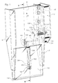
- the device comprises a magazine 2 in which the products P are stored.
- This store 2 has a wall 4 oriented substantially vertically and two side walls 6 and 8. It is provided with a tank 10 which is formed by a wall 12 extending opposite the wall 4 and a bottom 14 connecting the walls 4 and 12.
- the wall 4 is oriented so that the products P, under the only gravity action, can fall back into store 2 to come to rest on the bottom 14.
- the wall 4 is oriented vertically, but it will be understood that it can be tilted relative to the vertical by an angle determined by the coefficient of friction between the products P and the surface of this wall.
- the device further comprises an extraction system, designated by the general reference 16, which makes it possible to supply the P products, one by one, to a treatment, not shown, arranged downstream, upwards.
- an extraction system designated by the general reference 16, which makes it possible to supply the P products, one by one, to a treatment, not shown, arranged downstream, upwards.
- the extraction system 16 comprises means 18 for applying a force, towards wall 4, on all of the products P. These means have an electromagnet 20 fixed to the wall 12.
- a plate 22 is mounted articulated at 24 on the armature of the electromagnet opposite its core 26 against which it is attracted to (position shown in solid lines) when powered electrically by control means 28.
- a return spring 30 acts on the lower end of this plate so as to move it away from the core 26 (position shown schematically in dotted lines in FIG. 2) as soon as the electromagnet stops being supplied.
- An elastic blade 32, curved in direction of the wall 4 is fixed to the plate 22 by its lower end and carries at its upper end a shoe 34 which is applied to the products P so as to press them against the wall 4 when the electromagnet is supplied.
- This pad is made of polyurethane or any other material allowing the “pad on product P” friction is slightly higher than “product friction on product ".
- a notch 36 is formed in the wall 12.
- a stop 38 fixed in this notch, serves to limit the stroke of the blade when, under the action of the return spring 30, it is in the open position ( Figure 2), i.e. away from the products P.
- the extraction system 16 also comprises means 40 for driving the product P1 closest to the wall 4 upwards in the direction means of seizure 42.
- the drive means 40 comprise a roller 44 positioned, preferably substantially opposite the shoe 34 of the blade 32.
- This roller 44 is rotatably mounted on an axis 46 which extends transversely to the direction D of displacement of the products P in the device.
- axis 46 is guided in rotation by the wall 8 and an outer plate 48, which delimit between they have a space E.
- the plate 48 extends parallel to the wall 8 and is fixed to the latter by means of spacers 50 of which only one has been referenced.
- the wall 4 includes an oblong opening 52 through which the roller 44 protrudes to come into contact with the product P1 subjected to the action of the shoe 34.
- This roller preferably has a toothed outer edge, not referenced, provided to improve the training of P products and made, for example, in one synthetic material, especially an elastomer, such as silicone.
- Periphery roller is thus made up of a plurality of short flexible blades with high coefficient of friction.
- roller 44 can also have a smooth periphery, as soon as the material of this periphery has sufficient training characteristics of P. products
- the axis 46 carries, in its portion extending in the space E, a pulley 54 which is engaged with a belt 56 driven in rotation by an electric motor 58, the belt 56 not being shown in FIG. 1.
- Belt 56 and motor 58 constitute the motor means 60 of the roller 44.
- the gripping means 42 comprise a pair 42a of rollers 62 and 64 arranged in contact with each other, on the path of movement of the products P, on each side of the wall 4. This comprises, for this purpose, to the right of the two rollers, an opening 66 through which the roller 64 penetrates.
- the roller 62 is freely mounted for rotation on an axis integral with the wall 8, while the roller 64 is fixed on an axis 68 which extends in space E and which is guided in rotation by the wall 8 and plate 48.
- the pin 68 carries a pulley 70 which is also engaged with the belt 56 and which is therefore also driven by the motor means 60.
- the device further comprises, on the path of movement of the products P, three other pairs of rollers, referenced 42b, 42c and 42d, mounted and driven identically to the pair 42a of rollers 62 and 64.
- these four pairs of rollers 42a to 42d constitute the gripping means 42, but it will be understood that, in other variants of implementation of the device, more simplified or more elaborate, provision may be made for more or less number of pairs of rollers.
- the belt 56 also cooperates, in a conventional manner, with references R (of which only one has been referenced), mounted free to rotate in space E.
- the extraction system 16 also comprises means 72 for detect the handling of P products by the input means 42. More in particular, these detection means 72 act at the level of the first pair of rollers 42a.
- these means 72 comprise a light source 74 constituted advantageously by a photo-emitting diode (LED), placed at the right of the pair of rollers 42a, in the path of movement of the products P and fixed to the wall 8. Facing the source 74, the wall 4 is pierced with an opening 76 behind which is mounted a light detector 78, constituted, for example, by a photodiode.
- a light source 74 constituted advantageously by a photo-emitting diode (LED), placed at the right of the pair of rollers 42a, in the path of movement of the products P and fixed to the wall 8. Facing the source 74, the wall 4 is pierced with an opening 76 behind which is mounted a light detector 78, constituted, for example, by a photodiode.
- a light detector 78 constituted, for example, by a photodiode.
- Products P are introduced into the magazine 2 in a substantially position vertical and are stored in the bin 10 waiting to be extracted from the device.
- the electromagnet 20, controlled by the control means 28, applies the products P against the wall 4, by means of the elastic blade 32, so that the product P1 is in close contact with the roller 44 driven in rotation in the direction of the arrow F.
- the product P1 is then moved upwards, in the direction of the rollers 62 and 64 of the gripping means.
- the spring 30 releases the elastic blade 32 in the open position for a period of time predetermined (time delay) then applies again, under the action of the means control 28, the products P against the wall 4. Meanwhile, the product P1 continues its upward movement under the action of the other pairs of rollers 42b-42d until extracted from the device.
- the spring 30 releases the elastic blade 32 in open position until the detection means 72 announce the release of product P1.
- control means 28 respond to the signal emitted by the detection means 72 by giving the electromagnet 20 means 18 the order to exert force on the products P as long as the product P1 was not supported by the capture means 42 and cease the application of this force upon assumption of responsibility so as to fall back into tray 10 products P other than product P1 which could possibly have been moved to the gripping means 42 under the action of the driving means 40.
- an active separation system (not shown), known per se, consisting of two rollers mounted in the same way as those of gripping means, the roller disposed on the side of the wall 4 rotating in the direction which drives the product P1 upwards and the other roller rotating in the opposite direction of so as to push down a second product possibly accompanying the product P1.
Landscapes
- Engineering & Computer Science (AREA)
- Mechanical Engineering (AREA)
- Sheets, Magazines, And Separation Thereof (AREA)
Abstract
Description
- des moyens d'application d'une force pour plaquer contre ladite paroi le produit qui en est le plus proche.
- des moyens d'entraínement dudit produit le plus proche pour le déplacer vers le haut,
- des moyens de saisie pour prendre en charge ledit produit lorsqu'il a été déplacé d'une distance prédéterminée par lesdits moyens d'entraínement,
- des moyens de détection de la prise en charge du produit par lesdits moyens de saisie, ces moyens de détection étant capables de fournir un signal de détection, et
- des moyens de commande répondant audit signal de détection pour donner l'ordre auxdits moyens d'application d'exercer ladite force tant que le produit n'a pas été pris en charge par les moyens de saisie et de cesser l'application de cette force dès la prise en charge, de manière à faire retomber dans le magasin les produits autres que le produit au contact avec la paroi.
- la figure 1 est une vue schématique en perspective d'un mode de réalisation d'un dispositif selon l'invention, et
- la figure 2 est une vue en coupe du dispositif, selon la ligne II-II de la figure 1.
Claims (12)
- Dispositif pour la fourniture individuelle de produits plats (P) a un poste de traitement, comprenant un magasin (2) comportant une paroi (4) orientée de façon sensiblement verticale contre laquelle les produits sont juxtaposés et un système d'extraction (16) desdits produits pour les fournir un à un au poste de traitement, caractérisé en ce que ledit système comporte:des moyens d'application (18) d'une force pour plaquer contre ladite paroi (4) le produit (P1) qui en est le plus proche,des moyens d'entraínement (40) dudit produit le plus proche pour le déplacer vers le haut,des moyens de saisie (42) pour prendre en charge ledit produit lorsqu'il a été déplacé d'une distance prédéterminée par lesdits moyens d'entraínement,des moyens de détection (72) de la prise en charge du produit par lesdits moyens de saisie, ces moyens de détection étant capables de fournir un signal de détection, etdes moyens de commande (28) répondant audit signal de détection pour commander lesdits moyens d'application de manière que ceux-ci exercent ladite force, tant que le produit n'a pas été pris en charge par les moyens de saisie et cessent l'application de cette force dès la prise en charge, de manière à faire retomber dans le magasin (2) les produits autres que le produit au contact avec la paroi.
- Dispositif selon la revendication 1, caractérisé en ce que lesdits moyens d'application (18) comprennent une lame élastique (32) qui applique les produits contre ladite paroi et un électro-aimant (20) piloté par lesdits moyens de commande (28) et actionnant ladite lame élastique.
- Dispositif selon la revendication 1, caractérisé en ce que ledits moyens d'entraínement (40) comprennent au moins un galet entraíneur (44) et des moyens moteurs (60) pour mouvoir ledit galet en rotation.
- Dispositif selon les revendications 2 et 3, caractérisé en ce que ledit galet (44) est positionné sensiblement en regard de l'endroit où la lame (32) applique une force sur les produits.
- Dispositif selon l'une des revendications 3 et 4, caractérisé en ce que ledit galet (44) fait saillie au travers d'une ouverture (52) ménagée dans ladite paroi (4).
- Dispositif selon l'une des revendications 3 à 5, caractérisé en ce que ledit galet (44) présente un pourtour extérieur denté.
- Dispositif selon la revendication 6 , caractérisé en ce que le pourtour dudit galet (44) est réalisé en élastomère.
- Dispositif selon l'une des revendications 3 à 5, caractérisé en ce que ledit galet (44) est relié auxdits moyens moteurs (60) par l'intermédiaire d'une courroie (56).
- Dispositif selon la revendication 1, caractérisé en ce que ledits moyens de saisie (42) comprennent deux galets (62, 64) disposés en regard l'un de l'autre et des moyens moteurs (60) pour mouvoir lesdits galets en rotation.
- Dispositif selon les revendications 6 et 9, caractérisé en ce qu'au moins l'un desdits galets (64) est entraíné en rotation par ladite courroie (56).
- Dispositif selon la revendication 1, caractérisé en ce que ledits moyens de détection (72) comprennent un détecteur (78) disposé au voisinage desdits moyens de saisie (42).
- Dispositif selon la revendication 10, caractérisé en ce que ledit détecteur (78) est du type optique.
Applications Claiming Priority (3)
| Application Number | Priority Date | Filing Date | Title |
|---|---|---|---|
| FR9707811A FR2764874B1 (fr) | 1997-06-19 | 1997-06-19 | Dispositif pour la fourniture individuelle de produits plats a un poste de traitement |
| FR9707811 | 1997-06-19 | ||
| PCT/CH1998/000259 WO1998058862A1 (fr) | 1997-06-19 | 1998-06-15 | Dispositif pour la fourniture individuelle de produits plats a un poste de traitement |
Publications (2)
| Publication Number | Publication Date |
|---|---|
| EP1012092A1 EP1012092A1 (fr) | 2000-06-28 |
| EP1012092B1 true EP1012092B1 (fr) | 2002-02-13 |
Family
ID=9508315
Family Applications (1)
| Application Number | Title | Priority Date | Filing Date |
|---|---|---|---|
| EP98923969A Expired - Lifetime EP1012092B1 (fr) | 1997-06-19 | 1998-06-15 | Dispositif pour la fourniture individuelle de produits plats a un poste de traitement |
Country Status (6)
| Country | Link |
|---|---|
| US (1) | US6290223B1 (fr) |
| EP (1) | EP1012092B1 (fr) |
| JP (1) | JP2002504055A (fr) |
| DE (1) | DE69803859T2 (fr) |
| FR (1) | FR2764874B1 (fr) |
| WO (1) | WO1998058862A1 (fr) |
Families Citing this family (1)
| Publication number | Priority date | Publication date | Assignee | Title |
|---|---|---|---|---|
| JP2001106417A (ja) * | 1999-10-05 | 2001-04-17 | Oki Data Corp | 画像形成装置 |
Family Cites Families (5)
| Publication number | Priority date | Publication date | Assignee | Title |
|---|---|---|---|---|
| CH654255A5 (fr) * | 1983-06-03 | 1986-02-14 | Hermes Precisa International | Dispositif d'alimentation pour imprimante ou machine a ecrire. |
| US4640602A (en) * | 1984-06-25 | 1987-02-03 | Xerox Corporation | Sheet feeder-stacker |
| US4795145A (en) * | 1986-09-22 | 1989-01-03 | Centronics Data Computer Corporation | Cut sheet paper mechanism |
| JPH07172597A (ja) * | 1993-03-02 | 1995-07-11 | Fuji Xerox Co Ltd | 画像形成装置の縦型給紙装置 |
| US5836581A (en) * | 1996-10-11 | 1998-11-17 | Barco Graphics N.V. | Device and method for loading a sheet-like medium |
-
1997
- 1997-06-19 FR FR9707811A patent/FR2764874B1/fr not_active Expired - Fee Related
-
1998
- 1998-06-15 US US09/445,949 patent/US6290223B1/en not_active Expired - Fee Related
- 1998-06-15 DE DE69803859T patent/DE69803859T2/de not_active Expired - Fee Related
- 1998-06-15 WO PCT/CH1998/000259 patent/WO1998058862A1/fr not_active Ceased
- 1998-06-15 JP JP50348799A patent/JP2002504055A/ja active Pending
- 1998-06-15 EP EP98923969A patent/EP1012092B1/fr not_active Expired - Lifetime
Also Published As
| Publication number | Publication date |
|---|---|
| EP1012092A1 (fr) | 2000-06-28 |
| FR2764874B1 (fr) | 1999-09-03 |
| JP2002504055A (ja) | 2002-02-05 |
| FR2764874A1 (fr) | 1998-12-24 |
| DE69803859D1 (de) | 2002-03-21 |
| WO1998058862A1 (fr) | 1998-12-30 |
| DE69803859T2 (de) | 2002-11-28 |
| US6290223B1 (en) | 2001-09-18 |
Similar Documents
| Publication | Publication Date | Title |
|---|---|---|
| EP0195348B1 (fr) | Depileur d'objets plats | |
| CA2106906C (fr) | Depileur d'articles plats incluant un dispositif de retaquage | |
| FR2510433A1 (fr) | Appareil perfectionne d'avance, de manipulation et de comptage de documents en feuilles | |
| CH652992A5 (fr) | Trieuse de feuilles de papier, notamment des photocopies. | |
| EP0339059B1 (fr) | Appareil pour distribuer automatiquement des objets | |
| EP0017234B1 (fr) | Dispositif de séparation et d'extraction une à une de feuilles empilées | |
| EP2277810B1 (fr) | Dispositif d'alimentation à adhérence améliorée | |
| EP0645330B1 (fr) | Préhenseur d'objets plats et dispositif de dépilage équipé de ce préhenseur | |
| EP1012092A1 (fr) | Dispositif pour la fourniture individuelle de produits plats a un poste de traitement | |
| EP0115237B1 (fr) | Dispositif d'empilage d'objets plats | |
| EP2325808A1 (fr) | Dispositif de sélection d'articles de courrier à leviers perfectionnés | |
| EP0903248B1 (fr) | Dispositif de réorientation d'enveloppe | |
| FR2706165A1 (fr) | Appareil récepteur de feuilles à plateaux. | |
| CH688595A5 (fr) | Appareil d'alimentation de film pour une machine automatique de développement de film. | |
| FR2588537A1 (fr) | Distributeur de feuilles a frottement, notamment pour copieur automatique. | |
| EP0480822A1 (fr) | Dispositif pour la distribution rapide d'objets plats dans un convoyeur à godets | |
| EP0179010A1 (fr) | Dispositif de marge automatique pour machine à imprimer en sérigraphie à plateau sortant | |
| EP2292540B1 (fr) | Dispositif d'alimentation à séparation d'enveloppes améliorée | |
| EP0645331A1 (fr) | Dispositif de transfert d'objets plats et dispositif de dépilage équipé de ce dispositif de transfert | |
| FR2585682A1 (fr) | Dispositif d'extraction automatique sequentielle de feuilles de papier notamment pour les machines de traitement de documents | |
| EP0645327B1 (fr) | Magasin d'approvisionnement en objets plats et dispositif de dépilage d'objets plats équipé de ce magasin | |
| FR2627763A1 (fr) | Dispositif pour prelever a l'unite des elements en feuille, notamment des documents, a partir d'une pile | |
| FR2564445A1 (fr) | Dispositif d'alimentation un par un d'objets plats empiles, notamment de microfiches ou objets analogues | |
| EP2041008B1 (fr) | Méthode pour alimenter un dispositif de dépilage d'envois postaux | |
| FR2588536A1 (fr) | Distributeur de feuilles recues en paquet, notamment dans un copieur automatique. |
Legal Events
| Date | Code | Title | Description |
|---|---|---|---|
| PUAI | Public reference made under article 153(3) epc to a published international application that has entered the european phase |
Free format text: ORIGINAL CODE: 0009012 |
|
| 17P | Request for examination filed |
Effective date: 19991208 |
|
| AK | Designated contracting states |
Kind code of ref document: A1 Designated state(s): CH DE GB IT LI |
|
| GRAG | Despatch of communication of intention to grant |
Free format text: ORIGINAL CODE: EPIDOS AGRA |
|
| GRAG | Despatch of communication of intention to grant |
Free format text: ORIGINAL CODE: EPIDOS AGRA |
|
| GRAH | Despatch of communication of intention to grant a patent |
Free format text: ORIGINAL CODE: EPIDOS IGRA |
|
| 17Q | First examination report despatched |
Effective date: 20010719 |
|
| GRAH | Despatch of communication of intention to grant a patent |
Free format text: ORIGINAL CODE: EPIDOS IGRA |
|
| GRAA | (expected) grant |
Free format text: ORIGINAL CODE: 0009210 |
|
| REG | Reference to a national code |
Ref country code: GB Ref legal event code: IF02 |
|
| AK | Designated contracting states |
Kind code of ref document: B1 Designated state(s): CH DE GB IT LI |
|
| REG | Reference to a national code |
Ref country code: CH Ref legal event code: EP |
|
| REF | Corresponds to: |
Ref document number: 69803859 Country of ref document: DE Date of ref document: 20020321 |
|
| REG | Reference to a national code |
Ref country code: CH Ref legal event code: PFA Free format text: AXIOME ALPHA S.A.,5A, RUE DE LA GARE,2035 CORCELLES (CH) TRANSFER- AXIOME ALPHA SA,RUE DU CHASSELAS 1,2034 PESEUX (CH) Ref country code: CH Ref legal event code: NV Representative=s name: GRESSET - LAESSER CABINET DE CONSEILS EN PROPRIETE |
|
| PGFP | Annual fee paid to national office [announced via postgrant information from national office to epo] |
Ref country code: GB Payment date: 20020614 Year of fee payment: 5 |
|
| GBT | Gb: translation of ep patent filed (gb section 77(6)(a)/1977) |
Effective date: 20020524 |
|
| PGFP | Annual fee paid to national office [announced via postgrant information from national office to epo] |
Ref country code: DE Payment date: 20020828 Year of fee payment: 5 |
|
| PGFP | Annual fee paid to national office [announced via postgrant information from national office to epo] |
Ref country code: CH Payment date: 20020830 Year of fee payment: 5 |
|
| PLBE | No opposition filed within time limit |
Free format text: ORIGINAL CODE: 0009261 |
|
| STAA | Information on the status of an ep patent application or granted ep patent |
Free format text: STATUS: NO OPPOSITION FILED WITHIN TIME LIMIT |
|
| 26N | No opposition filed |
Effective date: 20021114 |
|
| PG25 | Lapsed in a contracting state [announced via postgrant information from national office to epo] |
Ref country code: GB Free format text: LAPSE BECAUSE OF NON-PAYMENT OF DUE FEES Effective date: 20030615 |
|
| PG25 | Lapsed in a contracting state [announced via postgrant information from national office to epo] |
Ref country code: LI Free format text: LAPSE BECAUSE OF NON-PAYMENT OF DUE FEES Effective date: 20030630 Ref country code: CH Free format text: LAPSE BECAUSE OF NON-PAYMENT OF DUE FEES Effective date: 20030630 |
|
| PG25 | Lapsed in a contracting state [announced via postgrant information from national office to epo] |
Ref country code: DE Free format text: LAPSE BECAUSE OF NON-PAYMENT OF DUE FEES Effective date: 20040101 |
|
| GBPC | Gb: european patent ceased through non-payment of renewal fee |
Effective date: 20030615 |
|
| REG | Reference to a national code |
Ref country code: CH Ref legal event code: PL |
|
| PG25 | Lapsed in a contracting state [announced via postgrant information from national office to epo] |
Ref country code: IT Free format text: LAPSE BECAUSE OF NON-PAYMENT OF DUE FEES;WARNING: LAPSES OF ITALIAN PATENTS WITH EFFECTIVE DATE BEFORE 2007 MAY HAVE OCCURRED AT ANY TIME BEFORE 2007. THE CORRECT EFFECTIVE DATE MAY BE DIFFERENT FROM THE ONE RECORDED. Effective date: 20050615 |