EP1012000B1 - Untergestell für einen fahrzeugsitz - Google Patents
Untergestell für einen fahrzeugsitz Download PDFInfo
- Publication number
- EP1012000B1 EP1012000B1 EP98954144A EP98954144A EP1012000B1 EP 1012000 B1 EP1012000 B1 EP 1012000B1 EP 98954144 A EP98954144 A EP 98954144A EP 98954144 A EP98954144 A EP 98954144A EP 1012000 B1 EP1012000 B1 EP 1012000B1
- Authority
- EP
- European Patent Office
- Prior art keywords
- shaped
- keyhole
- bellows
- frame according
- base part
- Prior art date
- Legal status (The legal status is an assumption and is not a legal conclusion. Google has not performed a legal analysis and makes no representation as to the accuracy of the status listed.)
- Expired - Lifetime
Links
- 230000037431 insertion Effects 0.000 description 2
- 238000003780 insertion Methods 0.000 description 2
- 239000000463 material Substances 0.000 description 2
- 235000001674 Agaricus brunnescens Nutrition 0.000 description 1
- 230000001747 exhibiting effect Effects 0.000 description 1
- 238000009434 installation Methods 0.000 description 1
- 239000002184 metal Substances 0.000 description 1
- 239000007769 metal material Substances 0.000 description 1
Images

Classifications
-
- B—PERFORMING OPERATIONS; TRANSPORTING
- B60—VEHICLES IN GENERAL
- B60N—SEATS SPECIALLY ADAPTED FOR VEHICLES; VEHICLE PASSENGER ACCOMMODATION NOT OTHERWISE PROVIDED FOR
- B60N2/00—Seats specially adapted for vehicles; Arrangement or mounting of seats in vehicles
- B60N2/50—Seat suspension devices
-
- B—PERFORMING OPERATIONS; TRANSPORTING
- B60—VEHICLES IN GENERAL
- B60N—SEATS SPECIALLY ADAPTED FOR VEHICLES; VEHICLE PASSENGER ACCOMMODATION NOT OTHERWISE PROVIDED FOR
- B60N2/00—Seats specially adapted for vehicles; Arrangement or mounting of seats in vehicles
- B60N2/58—Seat coverings
- B60N2/60—Removable protective coverings
- B60N2/6009—Removable protective coverings covering more than only the seat
-
- B—PERFORMING OPERATIONS; TRANSPORTING
- B60—VEHICLES IN GENERAL
- B60N—SEATS SPECIALLY ADAPTED FOR VEHICLES; VEHICLE PASSENGER ACCOMMODATION NOT OTHERWISE PROVIDED FOR
- B60N2/00—Seats specially adapted for vehicles; Arrangement or mounting of seats in vehicles
- B60N2/68—Seat frames
- B60N2/682—Joining means
Definitions
- the invention relates to a base for a Vehicle seat with a rectangular base, one rectangular shell and one between the base and the top provided and specified Bellows.
- a subframe of this kind is described in DE 1089285B disclosed.
- the bellows teardrop-shaped cones with a central blind hole are formed.
- the base and the top of such known bases are provided with holes in which are the protruding from the bellows male pin be plugged in.
- the respective central blind hole plugged in a pin-like tool, with which then the respective insertion pin in the associated hole in the basic or upper part is inserted. After inserting the plug into the associated Hole becomes the pin-shaped tool from the blind hole again pulled out. This represents a considerable installation effort represents.
- the invention is based on the object, a base to create the type mentioned, in which the said assembly effort is eliminated.
- This task is in a subframe of the beginning mentioned type solved according to the invention that the Base and / or the top with keyhole-shaped Holes and the bellows with associated keyhole-shaped, mushroom-like Einrastzapfen is trained.
- the keyhole-shaped holes in Base or in the upper part of the underframe from each other a distance to the distance between the associated Einrastzapfen is adapted so that the Einrastzapfen when plugging into the associated holes have to be slightly distanced from each other. After the arrangement of Einrastzapfen in the associated Holes are the Einrastzapfen then due to mechanical Relaxation squeezed in the holes. This results Thus, a mechanically reliable determination of the Bellows.
- the inventive frame keyhole-shaped holes are oriented such that at least two slot sections facing each other.
- the keyhole-shaped, mushroom-like Einrastzapfen against the said slot portions of the keyhole-shaped holes forced, creating a reliable determination of the Bellows at the base or at the top of the Underframe according to the invention is ensured.
- Each latching pin preferably has one Middle section and a cap portion with a elongated cross-sectional profile on.
- the cross-sectional profile the middle section is conveniently to the light Cross-sectional profile of the slot portion of the associated keyhole-shaped hole in the base or upper part of the Adapted underframe according to the invention.
- the central portion and the cap portion of the respective are keybar-shaped, mushroom-shaped Einrastzapfens preferably the same length, so that the cap portion only on both sides laterally beyond the central portion.
- a burr caused damage to the respective key - shaped, mushroom - type locking pin of the Bellows according to the invention can also be avoided by that the middle section towards the bellows at its extended two opposite end faces and that at the slot end of the associated keyhole-shaped hole in the base or cover part adjoining front on the cap section remote inside formed with a recess is.
- Such undercuts forming recesses or such undercuts forming key-bar-shaped, mushroom-like Einrastzapfen with a Middle section and one on both sides over the Central portion protruding cap portion are simple and easily realizable because of the bellows usually made of an elastically yielding Plastic material exists. That means on one Slider exhibiting, relatively complicated designed Mold for producing the bellows omitted can be.
- the base part and the upper part of the inventive Underframe usually consist of a suitable Metal sheet.
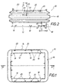
- Figures 1 and 2 show a bellows 10 with a Lower margin 12, with a top margin 14 and with a Fold portion 16 between the lower edge 12 and the Upper edge 14.
- the lower edge 12 is integral with keyhole-shaped, mushroom-like Einrastzapfen 18 and the Upper edge 14 is integral with key-bar-shaped, formed like mushroom-type latching pin 20, which below in connection with FIGS. 4 and 5 or 6 and 7 to be discribed.
- the latching pins 18 and 20 rest on the bellows 10 inside away.
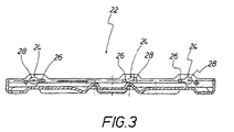
- FIG. 3 shows a sectional view of a base part 22 from a sheet metal material that is keyhole-shaped Holes 24 is formed.
- Fig. 3 are three such keyhole-shaped holes 24 to recognize, of which each hole 24 has a slot portion 26 and a extended insertion portion 28 has.
- the keyhole-shaped holes 24 are such oriented provided that at least two Slot sections 26 facing each other. Does that know Base 22 so on one of its four sides three keyhole-shaped holes 24 - as in Fig. 3rd is drawn, so have two (in Fig. 3, the two right) slot portions 26 in the same direction, and is the third (in Fig. 3, the left) slot portion 26th the two first-mentioned slot sections 26th facing. Are four keyhole-shaped holes 24 on the corresponding side of the base 22 - and / or not shown upper part of the undercarriage - provided, the slot sections 26 in pairs the same direction and the slot portions 26 of two pairs of holes are provided facing each other.
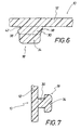
- Figures 4, 5 and 6, 7 illustrate sections of the Bellows 10 or its lower edge 12 (see Figures 6 and 7) or its upper edge 14 (see Figures 4 and 5). From the respective edge 12 and 14 are integrally inward directed latching pin 18 and 20 away, the one Central portion 30 (see Fig. 7) or a central portion 32 (see Fig. 5) and a cap portion 34 (see Fig. 7) or a cap portion 36 (see Fig. 5). As From Figures 4 and 6 can be seen, the respective Middle section 30 or 32 as long as the associated Cap portion 34 or 36, i. the respective one Cap portion 34 or 36 is only laterally over the Middle section 30 and 32 via, as shown in Figures 5 and 7 can be seen.
- Figures 4 and 6 also illustrate that the respective central portion 30 and 32 to the bellows 10 and to the corresponding edge 12 or 14 out at its two opposite longitudinal end faces 38 (see Fig. 6) or 40 (see Fig. 4) is conically widened, and that the am respective slot end of the associated keyhole-shaped hole 24 in the base 22 or in the Not shown cover part of the base frame fitting Front side 38 or 40 on the associated Cap portion 34 and 36 facing away from the inside with a Recess 42 (see Fig. 6) and 44 (see Fig. 4) formed is that to the non-disruptive recording of a possible existing ridge on the edge of the associated keyhole-shaped hole 24 is used.
Landscapes
- Engineering & Computer Science (AREA)
- Aviation & Aerospace Engineering (AREA)
- Transportation (AREA)
- Mechanical Engineering (AREA)
- Seats For Vehicles (AREA)
- Diaphragms And Bellows (AREA)
Description
- Fig. 1
- eine Draufsicht auf den Faltenbalg in einem verkleinerten Massstab,
- Fig. 2
- einen Schnitt entlang der Schnittlinie II-II in Fig.1 durch den Faltenbalg,
- Fig. 3
- einen Schnitt durch ein Grundteil aus einem Blechmaterial in einem verkleinerten Massstab
- Fig. 4
- stark vergrössert einen Schnitt entlang der Schnittlinie IV-IV in Fig.2 durch den Faltenbalg bzw. durch einen vom Faltenbalg wegstehenden schlüsselbartförmigen, pilzartigen Einrastzapfen,
- Fig. 5
- einen Schnitt entlang der Schnittlinie V-V in Fig.2 durch den Faltenbalg bzw. einen schlüsselförmigen, pilzartigen Einrastzapfen senkrecht zur Schnittebene gemäss Fig. 4 in einem stark vergrösserten Massstab,
- Fig. 6
- stark vergrössert einen Schnitt entlang der Schnittlinie VI-VI in Fig.2 durch einen anderen schlüsselbartförmigen, pilzartigen Einrastzapfen in einer der Fig. 4 ähnlichen Ansicht, und
- Fig. 7
- einen Schnitt entlang der Schnittlinie VII-VII in Fig.2 durch den zuletzt genannten Einrastzapfen, d.h. senkrecht zur Schnittebene gemäss Fig. 6 in einem vergrösserten Massstab.
Claims (6)
- Untergestell für einen Fahrzeugsitz mit einem rechteckigen Grundteil (22), einem rechteckigen Oberteil und einem zwischen dem Grundteil (22) und dem Oberteil vorgesehenen und daran festgelegten Faltenbalg (16),
dadurch gekennzeichnet, dass das Grundteil (22) und/oder das Oberteil mit schlüssellochförmigen Löchern (24) und dass der Faltenbalg (10) mit zugehörigen schlüsselbartförmigen, pilzartigen Einrastzapfen (18, 20) ausgebildet ist. - Untergestell nach Anspruch 1,
dadurch gekennzeichnet, dass die an der jeweiligen Seite des Grundteiles (22) und/oder des Oberteiles vorgesehenen schlüssellochförmigen Löcher (24) derartig orientiert sind, dass mindestens zwei ihrer Schlitzabschnitte (26) einander zugewandt sind. - Untergestell nach Anspruch 1 oder 2,
dadurch gekennzeichnet, dass die Schlitzabschnitte (26) der schlüssellochförmigen Löcher (24) zumindest aussenseitig mit einer Fase versehen sind. - Untergestell nach Anspruch 1,
dadurch gekennzeichnet, dass jeder schlüsselbartförmige, pilzartige Einrastzapfen (18, 20) einen Mittelabschnitt (30, 32) und einen Kappenabschnitt (34, 36) mit einem länglichen Querschnittsprofil aufweist. - Untergestell nach Anspruch 4,
dadurch gekennzeichnet, dass der Mittelabschnitt (30, 32) und der Kappenabschnitt (34, 36) gleich lang sind, so dass der Kappenabschnitt (34, 36) nur seitlich über den Mittelabschnitt (30, 32) übersteht. - Untergestell nach Anspruch 4,
dadurch gekennzeichnet, dass der Mittelabschnitt (30, 32) zum Faltenbalg (10) hin an seinen beiden voneinander abgewandten Längs-Stirnseiten (38, 40) erweitert und dass die am Schlitzende des zugehörigen schlüssellochförmigen Loches (24) im Grundteil (22) oder im Deckelteil anliegende Stirnseite (38, 40) auf der vom Kappenabschnitt (34, 36) abgewandten Innenseite mit einer Aussparung (42, 44) ausgebildet ist.
Applications Claiming Priority (3)
| Application Number | Priority Date | Filing Date | Title |
|---|---|---|---|
| DE19740377A DE19740377C1 (de) | 1997-09-13 | 1997-09-13 | Untergestell für einen Fahrzeugsitz |
| DE19740377 | 1997-09-13 | ||
| PCT/DE1998/002648 WO1999014074A1 (de) | 1997-09-13 | 1998-09-05 | Untergestell für einen fahrzeugsitz |
Publications (2)
| Publication Number | Publication Date |
|---|---|
| EP1012000A1 EP1012000A1 (de) | 2000-06-28 |
| EP1012000B1 true EP1012000B1 (de) | 2005-03-02 |
Family
ID=7842300
Family Applications (1)
| Application Number | Title | Priority Date | Filing Date |
|---|---|---|---|
| EP98954144A Expired - Lifetime EP1012000B1 (de) | 1997-09-13 | 1998-09-05 | Untergestell für einen fahrzeugsitz |
Country Status (3)
| Country | Link |
|---|---|
| EP (1) | EP1012000B1 (de) |
| DE (2) | DE19740377C1 (de) |
| WO (1) | WO1999014074A1 (de) |
Families Citing this family (1)
| Publication number | Priority date | Publication date | Assignee | Title |
|---|---|---|---|---|
| DE102006056599B3 (de) * | 2006-11-30 | 2008-06-12 | Isringhausen Gmbh & Co Kg | Faltenbalg sowie Verfahren zur Montage eines Faltenbalgs an einem Sitzrahmen |
Citations (1)
| Publication number | Priority date | Publication date | Assignee | Title |
|---|---|---|---|---|
| DE1089285B (de) * | 1956-07-05 | 1960-09-15 | Maschf Augsburg Nuernberg Ag | Gasgefederter Fahrzeugsitz |
Family Cites Families (3)
| Publication number | Priority date | Publication date | Assignee | Title |
|---|---|---|---|---|
| US4589620A (en) * | 1983-12-20 | 1986-05-20 | Tachikawa Spring Co., Ltd. | Seat with an air suspension |
| US5169112A (en) * | 1991-08-26 | 1992-12-08 | Milsco Manufacturing Company | Electronic suspension vehicle seat |
| FR2687959B1 (fr) * | 1992-02-27 | 1998-03-20 | Matra Automobile | Sieges amovibles pour vehicule et vehicule equipe de tels sieges. |
-
1997
- 1997-09-13 DE DE19740377A patent/DE19740377C1/de not_active Expired - Fee Related
-
1998
- 1998-09-05 DE DE59812624T patent/DE59812624D1/de not_active Expired - Lifetime
- 1998-09-05 WO PCT/DE1998/002648 patent/WO1999014074A1/de not_active Ceased
- 1998-09-05 EP EP98954144A patent/EP1012000B1/de not_active Expired - Lifetime
Patent Citations (1)
| Publication number | Priority date | Publication date | Assignee | Title |
|---|---|---|---|---|
| DE1089285B (de) * | 1956-07-05 | 1960-09-15 | Maschf Augsburg Nuernberg Ag | Gasgefederter Fahrzeugsitz |
Also Published As
| Publication number | Publication date |
|---|---|
| DE59812624D1 (de) | 2005-04-07 |
| DE19740377C1 (de) | 1999-01-28 |
| EP1012000A1 (de) | 2000-06-28 |
| WO1999014074A1 (de) | 1999-03-25 |
Similar Documents
| Publication | Publication Date | Title |
|---|---|---|
| DE2302932A1 (de) | Aufbewahrungsbehaelter fuer eine kassette | |
| DE60015473T2 (de) | Verbinder | |
| DE3415640A1 (de) | Verriegelungseinrichtung fuer elektrische verbinder | |
| DE69504805T2 (de) | Behälter für Compact Disc | |
| DE2446475A1 (de) | Spielzeug-steckbaustein | |
| DE19710515C1 (de) | Steckkarte für elektronische Geräte | |
| DE3217532A1 (de) | Gehaeuse zum einbau eines waermetauschers, insbesondere fuer eine heizungseinrichtung fuer den fahrgastraum eines kraftfahrzeuges | |
| EP1012000B1 (de) | Untergestell für einen fahrzeugsitz | |
| DE19652874C1 (de) | Haltedübel aus Kunststoff | |
| DE10336872B3 (de) | Magazinstreifen | |
| DE2254352C3 (de) | Druckknopf aus elastischem Kunststoff | |
| EP0969171A2 (de) | Abdeckung | |
| EP0262741B1 (de) | Scherkopf für einen Trockenrasierapparat. | |
| DE10114310C2 (de) | Innenverkleidung für ein Fahrzeug | |
| DE2529664C2 (de) | Sitzteilbezug für Kraftfahrzeugsitze, insbesondere Kopfstützenbezug | |
| DE19518041A1 (de) | Schnurklemme | |
| CH693429A5 (de) | Vorrichtung zur Aufnahme eines Tafelelements. | |
| CH687677A5 (de) | Bausatz zur Herstellung eines Spielzeugwuerfels. | |
| DE3409732C2 (de) | Einbau-Aschenbecher für Kraftfahrzeuge | |
| EP0647986B1 (de) | Kontaktstift für Steckverbindungen | |
| DE2801298C2 (de) | Einsteckverschluß | |
| DE3909687C2 (de) | ||
| DE4123117A1 (de) | Sonnenblende fuer kraftfahrzeuge | |
| DE19903422A1 (de) | Schließblech | |
| DE3218155A1 (de) | Verriegelungselement |
Legal Events
| Date | Code | Title | Description |
|---|---|---|---|
| PUAI | Public reference made under article 153(3) epc to a published international application that has entered the european phase |
Free format text: ORIGINAL CODE: 0009012 |
|
| 17P | Request for examination filed |
Effective date: 20000119 |
|
| AK | Designated contracting states |
Kind code of ref document: A1 Designated state(s): DE IT |
|
| GRAP | Despatch of communication of intention to grant a patent |
Free format text: ORIGINAL CODE: EPIDOSNIGR1 |
|
| GRAS | Grant fee paid |
Free format text: ORIGINAL CODE: EPIDOSNIGR3 |
|
| GRAA | (expected) grant |
Free format text: ORIGINAL CODE: 0009210 |
|
| AK | Designated contracting states |
Kind code of ref document: B1 Designated state(s): DE IT |
|
| REF | Corresponds to: |
Ref document number: 59812624 Country of ref document: DE Date of ref document: 20050407 Kind code of ref document: P |
|
| PLBE | No opposition filed within time limit |
Free format text: ORIGINAL CODE: 0009261 |
|
| STAA | Information on the status of an ep patent application or granted ep patent |
Free format text: STATUS: NO OPPOSITION FILED WITHIN TIME LIMIT |
|
| 26N | No opposition filed |
Effective date: 20051205 |
|
| PGFP | Annual fee paid to national office [announced via postgrant information from national office to epo] |
Ref country code: IT Payment date: 20140925 Year of fee payment: 17 |
|
| PG25 | Lapsed in a contracting state [announced via postgrant information from national office to epo] |
Ref country code: IT Free format text: LAPSE BECAUSE OF NON-PAYMENT OF DUE FEES Effective date: 20150905 |
|
| PGFP | Annual fee paid to national office [announced via postgrant information from national office to epo] |
Ref country code: DE Payment date: 20160906 Year of fee payment: 19 |
|
| REG | Reference to a national code |
Ref country code: DE Ref legal event code: R119 Ref document number: 59812624 Country of ref document: DE |
|
| PG25 | Lapsed in a contracting state [announced via postgrant information from national office to epo] |
Ref country code: DE Free format text: LAPSE BECAUSE OF NON-PAYMENT OF DUE FEES Effective date: 20180404 |