EP1009652B1 - Zweiradrahmen - Google Patents
Zweiradrahmen Download PDFInfo
- Publication number
- EP1009652B1 EP1009652B1 EP98951231A EP98951231A EP1009652B1 EP 1009652 B1 EP1009652 B1 EP 1009652B1 EP 98951231 A EP98951231 A EP 98951231A EP 98951231 A EP98951231 A EP 98951231A EP 1009652 B1 EP1009652 B1 EP 1009652B1
- Authority
- EP
- European Patent Office
- Prior art keywords
- frame
- accordance
- bicycle frame
- tensioning
- hook
- Prior art date
- Legal status (The legal status is an assumption and is not a legal conclusion. Google has not performed a legal analysis and makes no representation as to the accuracy of the status listed.)
- Expired - Lifetime
Links
Images


Classifications
-
- B—PERFORMING OPERATIONS; TRANSPORTING
- B62—LAND VEHICLES FOR TRAVELLING OTHERWISE THAN ON RAILS
- B62K—CYCLES; CYCLE FRAMES; CYCLE STEERING DEVICES; RIDER-OPERATED TERMINAL CONTROLS SPECIALLY ADAPTED FOR CYCLES; CYCLE AXLE SUSPENSIONS; CYCLE SIDE-CARS, FORECARS, OR THE LIKE
- B62K15/00—Collapsible or foldable cycles
Definitions
- the invention relates to a two-wheel frame according to the Preamble of claim 1 and a coupling device, especially for connecting such Bicycle frame.
- Automobile manufacturers have left in recent years to an increasing extent, in addition to vehicles to offer other brand-specific products.
- a special The focus is on high-quality bicycles, from the car manufacturer under their brand are offered by dealers, who are therefore in immediate Competition with bicycle dealers.
- the wheels are usually one in terms of construction Target group adapted by the respective car manufacturer wants to reach with his cars.
- So sports car manufacturers offer usually very sporty racing bikes and mountain bikes, while other companies Focus on touring or trekking bikes.
- the manufacturers also offer carrier systems to the constructive of the vehicle type and the Bicycle are adapted.
- FR-A-1514213 is a divisible bicycle frame known in which a down tube of the frame along a Parting plane can be divided into two frame parts and from which the present invention is based.
- One is planned Connection device for releasably joining the two frame parts on the parting plane, the connecting device an abutment with a support element, that is from a frame part through a the parting plane containing plane through to a support in the other Frame part extends, and has a clamping device for bracing the two frame parts so that the support element is supported on the support and the two frame parts face each other, the parting line a down tube penetrates in the two-wheel frame.
- the parting line runs essentially vertically to the longitudinal axis of the down tube.
- the invention is based on the object a divisible frame for a two-wheeler and a clutch system, especially for such divisible frames to create that with minimal device engineering Allow effort to reliably connect the components.
- this Support element accordingly a fastened in a down tube part Hook and the abutment one arranged in the other down tube part Bolt that is partially gripped by the hook and the encompassing portion of the hook transmits one acting in the direction of the two-wheel vertical axis Force component on the bolt.
- the frame parts are particularly easy to assemble, since the support element is hook-shaped and this hook-shaped section is supported on a bolt becomes.
- the direction of support is chosen such that it roughly in the direction of that initiated by the driver in the frame Forces occur so that the weight of the driver itself contributes to the connection between the support element and maintain the abutment.
- the hook-shaped Design of the support element makes it possible furthermore, the two frame parts with the tensioning device released to pivot against each other, this Swiveling movement by engagement of the hook-shaped part of the support element is guided on the bolt.
- connection device Since essentially no sliding fits are required is damage to the frame fit due to dirt almost impossible.
- the invention Structure of the connection device also allows simple cleaning of the components before assembly, so that a malfunction due to clamping etc. is prevented. Because the positive connection over the tensioning device and the abutment / support element takes place and the clamping force through appropriate readjustment the clamping device is changeable, manufacturing tolerances or wear of the joint without negative Impairment in the fit quality through readjustment the elasticity can be balanced.
- the tensioning device preferably has a pivotable one stored tensioning hook, the hook section with a other frame component attached clamping bolt into engagement is feasible.
- This tensioning device can, for example be designed as a toggle lever. However, it is preferred to store the tensioning hook on an eccentric shaft is rotatable by means of a clamping lever. Because of the eccentric Storage of the clamping hook can when closing the Clamping device applied a predetermined clamping force that holds the two frame parts together and that Support element presses on the abutment.
- the frame is preferably made of high-strength plastic, made of carbon fiber, for example the system sections of the frame components and the clamping device even formed in metal housing parts are preferably embedded in the plastic frame become.
- This combination of materials is on the one hand allows a very light frame, on the other hand is due to the metallic design of the housing parts wear of the frame in the parting line to a minimum reduced.
- the couplings for connecting the actuator for the brake and for the circuit is preferred trained with claws by relative movement of the two frame parts when assembling or disassembling of the frame engaged or disengaged are feasible.
- the actuators - preferably Bowden cables - no additional coupling devices are required as in the prior art described above (Hydraulic components, swivel levers) are provided, so that the installation space for the coupling device is minimal is.
- the claws according to the invention with mutually trained Engaging protrusions and grooves are preferably laterally to the longitudinal axis the actuator (Bowden cable) oriented so that the coupling / uncoupling movement not in the longitudinal direction the Bowden cables but in the transverse direction.
- the coupling parts are put together by a relative pivoting of the frame parts or uncoupled.
- Embodiment In another and considered to be particularly advantageous Embodiment is the tensioning device in the assembled Condition of the two frame parts of one Hold-down device, which is medium or immediate with a seat stay of the two-wheel frame in Connection is established.
- the fact that the clamping device in assembled state of the two frame parts of the Hold-down device is pressurized, the middle or immediate with the seat stay of the time frame is initially done in an advantageous manner an additional securing of the connection between the both frame parts through the over the seat stay the hold-down weight of the two-wheeler Person.
- the seat stay can be used as Opening lever used when separating the two frame parts be so that the opening of the clamping device for Detach the two frame parts from each other via the larger one Lever of the seat stay with a correspondingly lower one Force can be applied.
- clamping can also be done of the two frame parts when they are connected over the one provided by the seat stay longer levers with less effort.
- clamping lever can continue to hold down form, directly or indirectly with the seat stay of the two-wheel frame is connected.
- the clamping lever can be locked together with the Seat stay can be swiveled towards the other frame part is so that it has a bearing section in a recess of the other frame part.
- the parting plane is preferably about 45 ° to Down tube longitudinal axis employed.
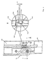
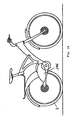
- Fig. 1 shows a schematic representation of an inventive Frame 1 for a sports bike.
- This frame 1 is made of high strength in the embodiment shown Plastic, for example made of carbon fibers and therefore has an extremely low weight.
- Plastic for example made of carbon fibers and therefore has an extremely low weight.
- the illustrated Wheel was chosen a self-resilient frame shape, where there is no conventional closed Frame triangle is used, but in the case of a saddle 2 and a storage of the rear wheel on cantilevered Frame end sections are arranged, thus a certain Have inherent elasticity.
- the frame in the illustration according to FIG. 1 U-shaped, so that a roughly horizontal extending top tube 6 and an obliquely downward Down tube 8 merged into a steering head 10 are. That which runs obliquely downwards from the steering head 10 Down tube 8 goes into a fork-shaped rear wheel mount 12 above, only in the illustration of FIG one leg of the rear wheel holder 12 can be seen.
- On the two end sections of the fork-shaped rear wheel mount 12 are fork end pieces, not shown, for receiving the rear wheel bearing provided.
- the bottom bracket with the associated cranks 14 In the connection area between the rear wheel holder 12 and the down tube 8 is the bottom bracket with the associated cranks 14 stored.
- a handlebar 16 and a front fork 18 stored for a front wheel 20 In the steering head 10 are a handlebar 16 and a front fork 18 stored for a front wheel 20.
- the frame 1 according to the invention is with a connecting device 24 provided, via which the down tube 8 in two down tube parts is separable, so that the frame 1 in two completely separate frame parts 26, 28 can be dismantled is.
- a connecting device 24 provided, via which the down tube 8 in two down tube parts is separable, so that the frame 1 in two completely separate frame parts 26, 28 can be dismantled is.
- the bottom bracket 28 with the bottom bracket Pedal cranks 14, the rear wheel mount 12 and the rear wheel stored, while on the upper frame part 26 of the saddle 2, the handlebar 16, the front fork 18 and the front wheel 20 are arranged.
- the Bowden cables are in the area of the parting plane 30 of the down tube 8 with detachable couplings or Coupling devices 32 provided.
- connection device 24 is actuated by means of a clamping lever 34, which in the embodiment shown is mounted on the lower frame part 28 and that in the closed state, i.e. when coupled together Frame parts 26, 28 pivoted toward the upper frame part 26 and is applied to the outer peripheral surface.
- a clamping lever 34 Around to allow the clamping lever 34 to be flush, is the down tube 8 in the swivel / contact area of the Swivel lever 34 is provided with a recess 36 into which the pivot lever 34 is immersed in the position shown, so that the frame in the area of the parting plane 30 if possible smooth surface without protruding parts.
- the Recess 36 is in the upper section in FIG. 1 with an engagement recess 38 executed so that the Swivel lever 34 better in its position shown is achievable.
- the parting plane 30 runs in the shown Embodiment approximately in the vertical direction, i.e. parallel to the vertical axis of the bike.
- the dividing plane can also be laid in a different way become.
- the invention is of course not on the illustrated U-shaped bicycle frame is limited, but that any frame construction can be used.
- connection device 24 not directly on the down tube parts stored, but these are included as insert parts executed housings 40, 42 provided, along the End faces the parting / contact plane 30 is formed and in which the bearings of the connecting device 24 are provided.
- housing 40, 42 in Area of the parting plane 30 becomes a connecting device with extremely high strength and low weight educated.
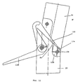
- Fig. 2 is a longitudinal section of the insert trained housing parts 40, 42 in uncoupled State shown.
- the two housings 40, 42 are in Lightweight construction cast from an aluminum alloy.
- This hook 46 is a tensioning hook in the lower housing 42 46 of the connecting device 24 mounted.
- This hook 46 has a hook-shaped curved end section 48, which consists of an end surface designed as an inclined surface 50 of the lower housing part 42 towards protrudes upper housing part 40.
- the tension hook 46 is in a receiving recess 52 of the lower housing 42 added.
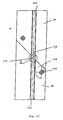
- This receiving recess 52 is shown 3 shown in cross section.
- This representation shows a section along the line A-A in Fig. 4 (left). Accordingly, the tensioning hook 46 is on the Eccentric 54 of an eccentric shaft 56, the end portions of which two laterally delimiting the receiving recess 52 Bearing walls 58, 60 of the lower housing part 42 enforce and in edge recesses 62, 64 of the housing 42 protrude into it.
- the clamping lever 34 has in the 3 is an arcuate arc Profile that matches the radius of curvature of the outer casing walls is adjusted so that the housing in the area between the two end portions of the eccentric shaft 46 from Clamping lever 34 and the two bearing sections 66, 68 in sections is encompassed.
- the eccentric shaft 56 is in the Bearing walls 58, 60 each have a bearing bush 70, 72 used.
- the eccentric is approximately in the middle 54 formed with two diametrically arranged flat surfaces 74.
- Eccentric 54 closes a central shaft section 76 on, in a radially stepped bearing collar 78 opens out, the storage section described above 68 of the clamping lever 34 passes through.
- the one in Fig. 5 left end portion of the eccentric shaft 54 is through a centric bearing collar 80 formed the bearing wall 60 and the lower bearing section 66 penetrated in FIG. 3.
- the two end faces of the eccentric shaft 54 are provided with threaded holes, not shown, in the Stop screws 82, 84 can be screwed in on the Outer sides of the bearing sections 66, 68 of the tensioning lever 34 issue.
- the upper bearing bush 70 in FIG. 3 is with the lower one End section (FIG. 3) on the eccentric end face 86 between the eccentric 54 and the central shaft section 76 supported.
- the one removed from this end face 86 End portion of the bearing bush 70 engages with a Radial collar the radial shoulder between the shaft sections 76, 78 of the eccentric shaft 56.
- the bearing sections 66, 68 of the clamping lever 34 each with an inner slot 88 designed to receive a bearing plate 90 serves.
- the bearing bush 70 In the assembly position shown 'is the radial collar side End face of the bearing bush 70 on the large area supported on the bearing plate 90, i.e. the bearing bush 70 extends to the adjacent peripheral wall of the inner slot 88 in the bearing section 68.
- the inner bore also is carried out with flat surfaces so that they are non-rotatable is connected to the eccentric shaft 56.
- the cam disc 92 (see Fig. 2) has a radially recessed one Circumferential groove 94 having a radial shoulder 96 at one end and has a driver cam 98 at the other end carries in the radial direction over the outer circumference of the Cam 92 stands out.
- the tension hook 46 is rotatably mounted on the eccentric 54, from the 2, a stop pin 100 protrudes, which is optionally in contact with the radial shoulder 96 or the driver cam 98 can be brought. That is, the Swiveling of the tensioning hook 56 around the eccentric 54 is by the abutment pin 100 against the radial shoulder 96 or the driver cam 98 limited.
- the upper housing 40 is - according to the illustration Fig. 2 - in extension of the clamping hook 46 with a Engagement recess 110 provided in the coupled State of the hook-shaped end portion 48 is immersed.
- This Engagement recess 110 is in the transverse direction (perpendicular to the drawing plane in Fig. 2) by a clamping bolt 112 enforced, which is shown enlarged in Fig. 6.
- the clamping pin 112 has two central bearing collars 114a, 114b, in each of which three are perpendicular to each other arranged blind holes 116 formed are.
- the fastening of the clamping bolt 112 in the engagement recess 110 is done by the two bearing collars 114a, 114b in the corresponding side walls of the engagement recess 110 are attached, in this Side walls from the sloping forehead / contact surface 120 grub screws 122 can be screwed in are, the cylindrical end portions in a immerse the blind holes 116 so that the clamping bolt 112 both in the axial direction and non-rotatably in upper housing 40 is attached.
- the installation position of the eccentric be selected so that manufacturing tolerances or wear by turning the clamping eccentric 118 can be compensated.
- the curvature of the hook surface 106 is on the outside diameter of the clamping eccentric 118 adapted, the hook-shaped end portion 48 in coupled state the eccentric 180 along about 150 ° embraces.
- the lower housing 42 has in the lower region a groove 124 that is perpendicular to the plane of the drawing in Fig. 2 is penetrated by a bolt 126 which in the Circumferential walls of the lower housing part 42 are pressed is.
- the groove 124 opens into the end face 50.
- the groove 124 is a hook in the upper housing 140 128 attached, the hook-shaped engagement portion 130 beyond the end face 120 towards the lower housing 42 projects.
- the engaging portion 130 has one Insertion nose 136, the width B is selected so that the Insertion nose 136 in the illustration according to FIG. 2 above of the bolt 26 can be inserted into the groove 124 or moved out is.
- the Interaction of the hook 128 with the bolt 126 is in following explained in more detail.
- a coupling part 144 is fastened to the upper housing 42, that at its left end section (view Fig. 2) has a mounting hole 146 into which an end portion of the Bowden cable 22a through the bottom of the middle wall 42 insertable and by means of clamping screws 148 is attachable.
- FIG. 2 Basic position is the coupling part 144 on the bottom of the Through hole of the middle wall 142 and is in Directed to the upper housing part 40 slidably.
- the movement of the coupling part 144 out of the upper housing 42 is limited by means of a stop 150, which dips into a longitudinal groove 172 of the coupling part 144 and thus also serves as an anti-rotation device.
- the two housing parts 40, 42 are coupled State shown, the clamping lever 34th is folded so that its operating portion on the outer circumference of the upper housing part 40.
- the coupling part 144 in a coupled state in active engagement with one Coupling part 152 stands, which is mounted in the upper housing 40 is.
- the two coupling parts 144 and 152 are with corresponding engagement sections forming a toothing trained, in the embodiment shown each coupling part 152, 144 on its End section with one extending transversely to the longitudinal axis Engagement projection 154 and a correspondingly trained Engagement groove 156 are provided.
- the axial length the engagement projection 154 is slightly less than the width of the engagement groove 156 of the associated coupling part educated.
- the engagement projections extend 154 in the radial direction over the central axis of the Coupling components 152, 144 also so that the engagement grooves 156 must be trained accordingly deep.
- the difference in length A between the Axial length of the engagement protrusions 154 and the engagement grooves 156 creates a certain idle stroke (play), so that when the Bowden cable is actuated Coupling part 152 moves in the direction of the arrow (Fig. 4) and only after the idle stroke A in contact with the side surface of the Engagement projection 154 of the coupling part 144 arrives.
- this idle stroke is chosen to be comparatively low, so that in practice it has no significance for the switching process or braking. If so, this idle stroke can also be dispensed with.
- the difference in length A makes it easier to loosen / join laterally the coupling parts 152, 144.
- the coupling part 152 is guided in a housing insert 162, that in a middle wall 164 of the upper housing part 40 is attached.
- the housing part 162 has a guide bore for the coupling part 152, which in a Through hole 166 of the middle wall 144 opens.
- the Bowden cable 22b passes through bore 166 and with its end section - as with coupling part 144 - Using clamping screws 148 in a mounting hole 146 set.
- the coupling part 152 by means of a an end face of the through hole 166 is supported Compression spring 168 biased towards the other coupling part 144.
- the axial movement of the coupling part 152 is again limited by a stop 170, which is in Fig. 2nd right end portion of the housing insert 162 attached and with an engagement section in a longitudinal groove 172 of the coupling part 152 dips and thus also as Protection against rotation serves.
- the clutch 32 described above can in principle be used to connect any molded parts are and is therefore in no way on the use limited in the context of a bicycle frame.
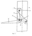
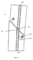
- Fig. 7 shows the frame 1 of the bicycle in a clutch State in which the two frame parts 26 and 28 meet are coupled.
- the two down tube parts are located along the end faces 50 and 120 on.
- the hook 128 lies with the support groove 138 and an area of the transverse shoulder on the bolt 126.
- the tensioning lever 34 is pivoted towards the frame part 26, so that the clamping hook 46 is in its clamping position, in which a tension force on the end faces 50, 120 and over the hook 128 on the bolt 126 is transferable. Is in this swivel position the eccentric 54 with its central axis in the farthest from the clamping pin 112 remote position so that the hook-shaped end portion 48 clamped with the clamping bolt 112 is.
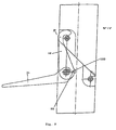
- the clamping lever is used to release the connection 34 pivoted about 90 °, so that the eccentric 54 also is rotated by 90 ° and thus the distance between the central axis of the eccentric 54 and the clamping bolt 112 decreased.
- 8 is the central axis of the eccentric 54 to the right of the central axis the eccentric shaft 56 is arranged. Through this Rotational movement of the eccentric 54 becomes the hook-shaped end section 48 of the clamping hook 46 is lifted off the clamping bolt 112, so that only a minor facility along an edge of the hook-shaped end portion 48 is present.
- the relative position of the two down tube parts has not yet compared in the illustration according to FIG. 8 that of Fig. 7 changed.
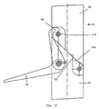
- the frame can now be turned around by pivoting the frame part 26 the bolt 126 are lifted off, with a recess 174 in the part at the bottom right (view according to FIG. 12) the end face 120 a collision-free relative pivoting allows so that the two end faces Move 120, 50 apart in a wedge shape.
- the frame part 26 is pivoted over the hook 128 on the bolt 126.
- the frame parts 26, 28 can then be pivoted and lifted further separate the upper frame part 26 from the lower frame part 28 and attach it to a roof rack or in one also comparatively small trunk or an emergency seat accommodate.
- the assembly takes place in the reverse way.
- the design of the coupling device according to the invention with the coaxial to the Bowden cables 22a, 22b Coupling parts 144, 152 allow an extreme compact design of the Bowden cable guide, being practical no additional aids for connection the coupling parts 152, 144 must be provided, but only a relative movement - here a swivel - Must be possible to face each other Engagement sections of the coupling parts 152, 144 to bring them into operative connection.
- This Coupling device can also be used for other connections deploy.
- a suitable lock can also be formed to separate the frame into two frame parts 26, 28 to avoid. Even if accidentally Loosened clamping lever 34, the two frame parts 26, 28 do not move apart because of the weight the driver pressed the hook 128 onto the bolt 126 and the two end faces 50, 120 are pressed together.
- the hook 128 is designed such that an axial offset of the two frame parts 26, 28 is excluded.
- FIG. 17 shows a further embodiment of a Two-wheel frame according to the invention, in which an accidental Loosen the connection device on special prevented simple, safe and elegant way can be without a push button lock or use another fuse or lock need to separate the frame into the two frame parts to avoid.
- FIGS. 1 to 16 are parts or sections, which to parts or sections in FIGS. 1 to 16 are the same or functionally equivalent, with the same Provide reference numerals and another detailed There is no description of this.
- FIG. 17 shows a schematic representation of the second Embodiment of the frame 1 for a sports bike.
- the Saddle 2 and the storage of the rear wheel 4 are again arranged on freely projecting frame end sections, the thus have a certain inherent elasticity.
- the frame 1 is substantially L-shaped with that of Steering head 10 from an obliquely downward / rearward down tube 8 and the substantially horizontal Rear wheel mount 12.
- the saddle 2 is free End of a seat stay 176 arranged in the extends substantially centrally from the down tube 8.
- the frame 1 is again with the connecting device 24 provided, via which the down tube 8 in two down tube parts is separable so that the frame 1 in the two completely separate frame parts 26 and 28 (Fig. 20) can be dismantled.
- the Bowden cables are in the area the parting plane 30 of the down tube 8 preferably with the already detachable couplings described above or Provide coupling devices.
- connection device 24 is actuated by means of the clamping lever 34, which on the upper frame part 28th is stored and in the closed state, i.e. when coupled together Frame parts 26 and 28 to the lower frame part 26 is pivoted out and on its outer peripheral surface is applied.
- the seat stay 176 is constructed in the shape of a triangle with two in the direction of the frame end section or there saddle 2 extending booms 178 and 180, which at the end opposite the end section in the area of the down tube 8 by acting as a hold-down Tension levers 34 are connected to one another.
- a Swiveling movement of the seat stay 176 in FIG. 17 in the clockwise direction around the longitudinal axis of the eccentric simultaneous entrainment of the clamping lever 34 and thus - as explained above - opening movement of the Clamping hook so that the two frame parts are apart can be separated.
- This process is also in the 19 to 21, with FIG. 19 the connecting device in the connected state analogous to FIG. 18 20 shows the two separate frame parts 21 shows the front frame part alone shows.
- the invention is Frame not on the in Figures 1 to 21 illustrated embodiments, but can be modified in different ways. So is, for example, in the embodiment of FIG Parting plane between the two frame parts 26 and 28 not horizontally, but essentially vertically.
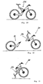
- Fig. 23 shows a modification example in which the Rear wheel mount 12 via a corresponding linkage 182 and a spring 184 resiliently on the rear or lower Frame part 26 is mounted.
- 24 shows an embodiment of a so-called motor bike, which additionally or alternatively to the drive via pedals Rear wheel 4 via an electric or internal combustion engine 186 can be driven.
- front frame part 28 remains unchanged; it will only the rear frame part 26 modified accordingly or modified what from an economic point of view forth is particularly advantageous.
- tension lever and seat post can be use of course also with coupling devices, which have a different structure than the one described above exhibit.
- a frame for a two-wheeler in which the End faces of a frame part by a clamping device are braced against each other, so that a support element is supported on an abutment and thus the Frame parts positively and positively connected are.
- a coupling device is also disclosed for connecting two components.
Landscapes
- Engineering & Computer Science (AREA)
- Mechanical Engineering (AREA)
- Mutual Connection Of Rods And Tubes (AREA)
- Automatic Cycles, And Cycles In General (AREA)
- Motorcycle And Bicycle Frame (AREA)
- Clamps And Clips (AREA)
Applications Claiming Priority (7)
| Application Number | Priority Date | Filing Date | Title |
|---|---|---|---|
| DE19738778 | 1997-09-04 | ||
| DE19738778 | 1997-09-04 | ||
| DE19738969A DE19738969B4 (de) | 1997-09-04 | 1997-09-05 | Zweiradrahmen |
| DE19738969 | 1997-09-05 | ||
| DE1998135242 DE19835242A1 (de) | 1998-08-04 | 1998-08-04 | Teilbarer Zweiradrahmen |
| DE19835242 | 1998-08-04 | ||
| PCT/DE1998/002536 WO1999011511A1 (de) | 1997-09-04 | 1998-08-28 | Zweiradrahmen |
Publications (2)
| Publication Number | Publication Date |
|---|---|
| EP1009652A1 EP1009652A1 (de) | 2000-06-21 |
| EP1009652B1 true EP1009652B1 (de) | 2003-02-12 |
Family
ID=27217720
Family Applications (1)
| Application Number | Title | Priority Date | Filing Date |
|---|---|---|---|
| EP98951231A Expired - Lifetime EP1009652B1 (de) | 1997-09-04 | 1998-08-28 | Zweiradrahmen |
Country Status (8)
| Country | Link |
|---|---|
| US (1) | US6364334B1 (ja) |
| EP (1) | EP1009652B1 (ja) |
| JP (1) | JP3837287B2 (ja) |
| AT (1) | ATE232483T1 (ja) |
| AU (1) | AU9735598A (ja) |
| CA (1) | CA2302935C (ja) |
| ES (1) | ES2191347T3 (ja) |
| WO (1) | WO1999011511A1 (ja) |
Families Citing this family (18)
| Publication number | Priority date | Publication date | Assignee | Title |
|---|---|---|---|---|
| ES2275421B1 (es) | 2005-07-29 | 2008-05-01 | Orbea S. Coop. Ltda. | Cuadro de bicicleta. |
| NL1034108C2 (nl) * | 2007-07-06 | 2009-01-08 | Nicolaas Petrus Luiten | Voertuig. |
| DE102007037648B4 (de) * | 2007-08-09 | 2010-11-25 | Topeak, Inc. | Faltrad |
| JP4691076B2 (ja) * | 2007-08-16 | 2011-06-01 | 巨大機械工業股▲分▼有限公司 | 自転車の折畳み式フレームの安全ロック装置 |
| US20140274582A1 (en) * | 2013-03-14 | 2014-09-18 | KinderBike, Ltd | Training Equipment with Alternative Assembly Modules |
| US9580130B2 (en) | 2015-02-26 | 2017-02-28 | Ford Global Technologies, Llc | Bicycle with detachable head-tube subassembly |
| US10919594B2 (en) * | 2016-01-27 | 2021-02-16 | Ford Global Technologies, Llc | Foldable bicycle and storage system |
| CN108883804B (zh) | 2016-01-27 | 2021-01-29 | 福特全球技术公司 | 可折叠自行车和存放系统 |
| CA171390S (en) * | 2016-05-13 | 2017-06-13 | Zhejiang Right Digital Tech Co Ltd | Electric bicycle |
| USD1011968S1 (en) * | 2021-08-23 | 2024-01-23 | Shenzhen Zhelun Tech Co., Ltd. | Bicycle |
| JP1709502S (ja) * | 2021-08-31 | 2022-03-10 | 電動アシスト自転車用フレーム | |
| USD1009716S1 (en) * | 2022-01-10 | 2024-01-02 | Trek Bicycle Corporation | Bicycle frame with cantilevered seat post |
| USD1003201S1 (en) * | 2022-01-20 | 2023-10-31 | Dongguan Onesport Technology Co., Ltd | Electric bicycle |
| USD1008884S1 (en) * | 2022-01-24 | 2023-12-26 | Galaxy Bicycle Co., Ltd. | Bicycle frame |
| USD1008883S1 (en) * | 2022-01-24 | 2023-12-26 | Galaxy Bicycle Co., Ltd. | Bicycle frame |
| USD1008882S1 (en) * | 2022-01-24 | 2023-12-26 | Galaxy Bicycle Co., Ltd. | Bicycle frame |
| USD1008881S1 (en) * | 2022-01-24 | 2023-12-26 | Galaxy Bicycle Co., Ltd. | Bicycle frame |
| USD1027734S1 (en) * | 2022-08-03 | 2024-05-21 | Mobility Holdings, Limited | Bicycle frame |
Family Cites Families (5)
| Publication number | Priority date | Publication date | Assignee | Title |
|---|---|---|---|---|
| NL6401631A (ja) * | 1964-02-21 | 1965-08-23 | ||
| FR1501565A (fr) * | 1965-11-26 | 1967-11-10 | Castello Mario & Figlio S R L | Cadre démontable de bicyclette |
| FR1514213A (fr) * | 1965-12-17 | 1968-02-23 | O M P Ohg Ponti & C S N C E Fl | Bicyclette à deux places transformable en bicyclette monoplace |
| DE4423647A1 (de) | 1994-07-06 | 1996-01-11 | Thomas Mueller | Fahrrad |
| DE29513779U1 (de) | 1995-08-28 | 1995-11-23 | Fichtner Hans | Fahrrad |
-
1998
- 1998-08-28 WO PCT/DE1998/002536 patent/WO1999011511A1/de active IP Right Grant
- 1998-08-28 JP JP2000508575A patent/JP3837287B2/ja not_active Expired - Fee Related
- 1998-08-28 EP EP98951231A patent/EP1009652B1/de not_active Expired - Lifetime
- 1998-08-28 AU AU97355/98A patent/AU9735598A/en not_active Abandoned
- 1998-08-28 US US09/486,845 patent/US6364334B1/en not_active Expired - Fee Related
- 1998-08-28 ES ES98951231T patent/ES2191347T3/es not_active Expired - Lifetime
- 1998-08-28 CA CA002302935A patent/CA2302935C/en not_active Expired - Fee Related
- 1998-08-28 AT AT98951231T patent/ATE232483T1/de active
Also Published As
| Publication number | Publication date |
|---|---|
| JP3837287B2 (ja) | 2006-10-25 |
| WO1999011511A1 (de) | 1999-03-11 |
| EP1009652A1 (de) | 2000-06-21 |
| JP2001514124A (ja) | 2001-09-11 |
| CA2302935C (en) | 2006-01-17 |
| ATE232483T1 (de) | 2003-02-15 |
| ES2191347T3 (es) | 2003-09-01 |
| AU9735598A (en) | 1999-03-22 |
| CA2302935A1 (en) | 1999-03-11 |
| US6364334B1 (en) | 2002-04-02 |
Similar Documents
| Publication | Publication Date | Title |
|---|---|---|
| EP1009652B1 (de) | Zweiradrahmen | |
| EP3590813B1 (de) | Fahrrad mit batteriebetriebenem hilfsantrieb und fahrradrahmen hierfür | |
| DE60029148T3 (de) | Hilfsschaltvorrichtung in einer Fahrradgangschaltung | |
| EP2838782B1 (de) | Selbstverriegelnde kompakt-kupplung | |
| WO2015051472A1 (de) | Zweirad mit einer hinterradfederung | |
| DE3701803A1 (de) | Faltbares zweiraedriges fahrrad | |
| DE1976103U (de) | Zerlegbarer fahrradrahmen. | |
| DE202006004697U1 (de) | Radbremse | |
| DE102004043251B4 (de) | Rahmenanordnung eines Kleinfahrzeugs | |
| DE102012111204A1 (de) | Rotorsystem für ein Fahrrad | |
| WO1999011512A1 (de) | Kupplungseinrichtung | |
| AT518187B1 (de) | Kabelführungskörper | |
| DE19738971B4 (de) | Kupplungseinrichtung | |
| EP1266816B1 (de) | Verriegelungseinheit für eine einstellbare Lenksäule | |
| DE19507921A1 (de) | Fahrradrahmen | |
| DE112021001205T5 (de) | Querträger und Kupplungsbauteil für einen Querträger | |
| DE19924350C2 (de) | Zusammenlegbares Fahrrad | |
| DE4023690A1 (de) | Motorgetriebener, nachgefuehrter golfwagen | |
| EP0943487A2 (de) | Vorrichtung zum lösbaren Verbinden mit einem Bügel | |
| DE3709418A1 (de) | Handbremse fuer kraftfahrzeuge | |
| EP3521150B1 (de) | Rahmenvorrichtung für ein neigefahrzeug sowie neigefahrzeug | |
| DE10155889A1 (de) | Lenker für Fortbewegungsmittel, wie Fahrräder, Roller oder dergleichen | |
| DE202016002376U1 (de) | Fahrrad mit klappbar ausgebildeter Rahmenstruktur | |
| DE19835242A1 (de) | Teilbarer Zweiradrahmen | |
| DE19948675B4 (de) | Vorrichtung zum Schließen und Öffnen eines verriegelbaren Deckelteils, insbesondere eines Fahrzeugdeckelteils für eine Kofferraumverkleidung |
Legal Events
| Date | Code | Title | Description |
|---|---|---|---|
| PUAI | Public reference made under article 153(3) epc to a published international application that has entered the european phase |
Free format text: ORIGINAL CODE: 0009012 |
|
| 17P | Request for examination filed |
Effective date: 20000308 |
|
| AK | Designated contracting states |
Kind code of ref document: A1 Designated state(s): AT CH DE ES FR IT LI NL |
|
| 17Q | First examination report despatched |
Effective date: 20010330 |
|
| GRAG | Despatch of communication of intention to grant |
Free format text: ORIGINAL CODE: EPIDOS AGRA |
|
| GRAG | Despatch of communication of intention to grant |
Free format text: ORIGINAL CODE: EPIDOS AGRA |
|
| GRAH | Despatch of communication of intention to grant a patent |
Free format text: ORIGINAL CODE: EPIDOS IGRA |
|
| GRAH | Despatch of communication of intention to grant a patent |
Free format text: ORIGINAL CODE: EPIDOS IGRA |
|
| GRAA | (expected) grant |
Free format text: ORIGINAL CODE: 0009210 |
|
| AK | Designated contracting states |
Designated state(s): AT CH DE ES FR IT LI NL |
|
| REG | Reference to a national code |
Ref country code: CH Ref legal event code: EP |
|
| REG | Reference to a national code |
Ref country code: CH Ref legal event code: NV Representative=s name: SCHMAUDER & PARTNER AG PATENTANWALTSBUERO |
|
| REF | Corresponds to: |
Ref document number: 59807200 Country of ref document: DE Date of ref document: 20030320 Kind code of ref document: P |
|
| REG | Reference to a national code |
Ref country code: ES Ref legal event code: FG2A Ref document number: 2191347 Country of ref document: ES Kind code of ref document: T3 |
|
| ET | Fr: translation filed | ||
| PLBE | No opposition filed within time limit |
Free format text: ORIGINAL CODE: 0009261 |
|
| STAA | Information on the status of an ep patent application or granted ep patent |
Free format text: STATUS: NO OPPOSITION FILED WITHIN TIME LIMIT |
|
| 26N | No opposition filed |
Effective date: 20031113 |
|
| REG | Reference to a national code |
Ref country code: CH Ref legal event code: PCAR Free format text: SCHMAUDER & PARTNER AG PATENT- UND MARKENANWAELTE VSP;ZWAENGIWEG 7;8038 ZUERICH (CH) |
|
| PGFP | Annual fee paid to national office [announced via postgrant information from national office to epo] |
Ref country code: DE Payment date: 20140801 Year of fee payment: 17 Ref country code: CH Payment date: 20140821 Year of fee payment: 17 Ref country code: NL Payment date: 20140821 Year of fee payment: 17 |
|
| PGFP | Annual fee paid to national office [announced via postgrant information from national office to epo] |
Ref country code: ES Payment date: 20140827 Year of fee payment: 17 Ref country code: FR Payment date: 20140819 Year of fee payment: 17 Ref country code: AT Payment date: 20140820 Year of fee payment: 17 |
|
| PGFP | Annual fee paid to national office [announced via postgrant information from national office to epo] |
Ref country code: IT Payment date: 20140825 Year of fee payment: 17 |
|
| REG | Reference to a national code |
Ref country code: DE Ref legal event code: R119 Ref document number: 59807200 Country of ref document: DE |
|
| REG | Reference to a national code |
Ref country code: CH Ref legal event code: PL |
|
| REG | Reference to a national code |
Ref country code: AT Ref legal event code: MM01 Ref document number: 232483 Country of ref document: AT Kind code of ref document: T Effective date: 20150828 |
|
| PG25 | Lapsed in a contracting state [announced via postgrant information from national office to epo] |
Ref country code: LI Free format text: LAPSE BECAUSE OF NON-PAYMENT OF DUE FEES Effective date: 20150831 Ref country code: CH Free format text: LAPSE BECAUSE OF NON-PAYMENT OF DUE FEES Effective date: 20150831 Ref country code: IT Free format text: LAPSE BECAUSE OF NON-PAYMENT OF DUE FEES Effective date: 20150828 |
|
| REG | Reference to a national code |
Ref country code: NL Ref legal event code: MM Effective date: 20150901 |
|
| PG25 | Lapsed in a contracting state [announced via postgrant information from national office to epo] |
Ref country code: AT Free format text: LAPSE BECAUSE OF NON-PAYMENT OF DUE FEES Effective date: 20150828 |
|
| REG | Reference to a national code |
Ref country code: FR Ref legal event code: ST Effective date: 20160429 |
|
| PG25 | Lapsed in a contracting state [announced via postgrant information from national office to epo] |
Ref country code: NL Free format text: LAPSE BECAUSE OF NON-PAYMENT OF DUE FEES Effective date: 20150901 |
|
| PG25 | Lapsed in a contracting state [announced via postgrant information from national office to epo] |
Ref country code: DE Free format text: LAPSE BECAUSE OF NON-PAYMENT OF DUE FEES Effective date: 20160301 |
|
| PG25 | Lapsed in a contracting state [announced via postgrant information from national office to epo] |
Ref country code: FR Free format text: LAPSE BECAUSE OF NON-PAYMENT OF DUE FEES Effective date: 20150831 |
|
| REG | Reference to a national code |
Ref country code: ES Ref legal event code: FD2A Effective date: 20160926 |
|
| PG25 | Lapsed in a contracting state [announced via postgrant information from national office to epo] |
Ref country code: ES Free format text: LAPSE BECAUSE OF NON-PAYMENT OF DUE FEES Effective date: 20150829 |