EP1009263B9 - Procede et appareil de support d'un element a supporter, en particulier le corps d'un patient permettant un support a une ligne de flottaison predeterminee - Google Patents
Procede et appareil de support d'un element a supporter, en particulier le corps d'un patient permettant un support a une ligne de flottaison predeterminee Download PDFInfo
- Publication number
- EP1009263B9 EP1009263B9 EP97952969A EP97952969A EP1009263B9 EP 1009263 B9 EP1009263 B9 EP 1009263B9 EP 97952969 A EP97952969 A EP 97952969A EP 97952969 A EP97952969 A EP 97952969A EP 1009263 B9 EP1009263 B9 EP 1009263B9
- Authority
- EP
- European Patent Office
- Prior art keywords
- measurement
- supported
- reaction
- patient
- chamber
- Prior art date
- Legal status (The legal status is an assumption and is not a legal conclusion. Google has not performed a legal analysis and makes no representation as to the accuracy of the status listed.)
- Expired - Lifetime
Links
Images


Classifications
-
- A—HUMAN NECESSITIES
- A61—MEDICAL OR VETERINARY SCIENCE; HYGIENE
- A61G—TRANSPORT, PERSONAL CONVEYANCES, OR ACCOMMODATION SPECIALLY ADAPTED FOR PATIENTS OR DISABLED PERSONS; OPERATING TABLES OR CHAIRS; CHAIRS FOR DENTISTRY; FUNERAL DEVICES
- A61G7/00—Beds specially adapted for nursing; Devices for lifting patients or disabled persons
- A61G7/05—Parts, details or accessories of beds
- A61G7/057—Arrangements for preventing bed-sores or for supporting patients with burns, e.g. mattresses specially adapted therefor
- A61G7/05769—Arrangements for preventing bed-sores or for supporting patients with burns, e.g. mattresses specially adapted therefor with inflatable chambers
-
- A—HUMAN NECESSITIES
- A61—MEDICAL OR VETERINARY SCIENCE; HYGIENE
- A61G—TRANSPORT, PERSONAL CONVEYANCES, OR ACCOMMODATION SPECIALLY ADAPTED FOR PATIENTS OR DISABLED PERSONS; OPERATING TABLES OR CHAIRS; CHAIRS FOR DENTISTRY; FUNERAL DEVICES
- A61G2203/00—General characteristics of devices
- A61G2203/30—General characteristics of devices characterised by sensor means
- A61G2203/34—General characteristics of devices characterised by sensor means for pressure
-
- A—HUMAN NECESSITIES
- A61—MEDICAL OR VETERINARY SCIENCE; HYGIENE
- A61G—TRANSPORT, PERSONAL CONVEYANCES, OR ACCOMMODATION SPECIALLY ADAPTED FOR PATIENTS OR DISABLED PERSONS; OPERATING TABLES OR CHAIRS; CHAIRS FOR DENTISTRY; FUNERAL DEVICES
- A61G2203/00—General characteristics of devices
- A61G2203/30—General characteristics of devices characterised by sensor means
- A61G2203/40—General characteristics of devices characterised by sensor means for distance
Definitions
- the invention relates to a method and an apparatus for supporting a element to be supported, in particular of a patient's body, allowing a support to the balance of the element to be supported, essentially corresponding to a line of floatation thereof predetermined.
- a device for supporting an element to be supported, in particular the body of a patient who must be bedridden or immobilized for a period of time extended, usually mainly known as a mattress, is fine known. It is also well known that bed rest or immobilization prolonged period leads to complications, including pressure sores.
- EP-A-676 158 a method and a system for supporting an element to be supported, in particular the body of a patient, allowing support at a depth of controlled sinking, essentially constant using a measurement of the insertion distance different from the previous document by the fact that the measuring means comprise on the one hand a metallic element under shape of a thin sheet placed towards the upper face of the support element cooperating with at least one inductive device forming a position detector secured to the underside of the support element.
- a slaving of the filling or deflating of the chamber of the element of support is provided to lead to the predetermined insertion distance, and whatever the weight of the element to be supported, in particular the body of a patient.
- the present invention aims to solve the new technical problem consisting in providing a solution which allows support an element to be supported, in particular the body of a patient, essentially a position of natural equilibrium which corresponds substantially to a waterline that is preferably defined beforehand.
- the invention also aims to solve this new problem technique in particular in the context of patient support, in order to obtain the expected performance in terms of prevention or treatment of complications from bed rest or prolonged immobilization, and particularly depending on the morphological characteristics of the part apparent submergence, including weight and body surface, plus generally the weight and the surface of the element to support.
- the main object of the present invention is also to resolve the new technical problem consisting in providing a solution which allows to analyze and control the sinking of an element to be supported, in particularly the body of a patient, in the support device and the reaction of said support device exerted on the element to be supported, in particular the body of a patient, so that optimal pressures are applied to the surface body in contact with the support device, which is particularly sought in the prevention and treatment of complications related to prolonged bed rest and immobilization, especially bedsores.
- the present invention provides for the first time a solution to all the technical problems previously stated in a simple manner, inexpensive, safe and reliable, easy to use and usable on a scale industrial and medical.
- the present invention provides a method of supporting an element to be supported, in particular the body of a patient, comprising the provision of at least one support device comprising at least a closed or flexible, inflatable, controlled-exhaust chamber, said chamber having an upper face and a lower face; filling means or evacuation of a filling fluid from said chamber being provided as well as means for measuring the distance separating said upper face relative to said lower face, characterized in that a device is further provided measuring the response of the support device to the data of the element to be supported, characterized in that one proceeds to the measurement of the driving distance of the element to be supported in the device support, we measure the reaction of the support device to the penetration of the element to be supported comprising measuring the pressure in said chamber said measured driving distance and these two measurements are combined to bring the element to be supported substantially to the corresponding equilibrium substantially at a predetermined waterline.
- the aforementioned combination of distance measurement sinking and measuring the reaction of the support device includes a summation of these two values.
- this method is characterized in that that the above summation consists of a summation of the distance value and the pressure value in the chamber.
- this method is characterized in that that the above combination of driving distance value and reaction measurement is compared to a reference value characterizing the value of the driving force of the element to be supported corresponding substantially to the predetermined water line of said element to be supported.
- this method is characterized in that that the aforementioned predetermined reference value defining the equilibrium substantially corresponding to the waterline is fixed to achieve the expected performance in terms of prevention or treatment of the patient, particularly complications related to bed rest or immobilization prolonged, including pressure sores.
- this method is characterized in that that the operation of the filling or evacuation means is controlled results of the above combination of driving distance and measurement of the reaction of the support device. results of the above combination of driving distance and measurement of the reaction of the support device.
- a support device or mattress comprising a multitude of cushions or sausages which can be deflated alternately individually, sequentially, in particular one carries out a sequential deflation one on two, one on three or one on four or one in n, thereby avoiding relatively high pressures to the different parts of the element to be supported, in particular the body of a which are detrimental to the treatment and comfort of certain types of Patients, especially patients who have had a skin transplant or patients being subject to acute pain following certain diseases.
- the present invention also provides a device for supporting an element to be supported, in particular the body of a patient, comprising at least one support device comprising at least one chamber closed or controlled, flexible, inflatable exhaust, said chamber having a upper face and lower face, filling or discharge means a fluid for filling said chamber as well as means for measuring the distance separating said upper face relative to said lower face, characterized in that it further comprises a device for measuring the reaction of the support device relative to the morphological data of the element to support including a device for measuring the pressure in the chamber support device at the measured insertion distance, a control comprising means for combining distance measurement of penetration provided by the measuring device and measuring the reaction supplied by the reaction measurement device, to bring the element to be supported substantially at equilibrium corresponding substantially to a waterline predetermined.
- the combination device of the control system performs the summation of the penetration distance measurement with the measurement of the reaction provided by the reaction measurement device.
- this device is characterized in that that the combination device is connected to a comparison device which performs a comparison of the combination value provided by the combination with a reference value provided by a reference device, this reference value characterizing the equilibrium depression value of the element to be supported corresponding substantially to the waterline predetermined element to support.
- this device is characterized in what the aforementioned reference value predetermined and defining the balance substantially corresponding to the waterline is fixed to achieve the expected performance of prevention or treatment of the patient, particularly complications related to bed rest or immobilization prolonged, including pressure sores.
- this device is characterized in what it includes a servo device realizing a servo of the operation of the filling or evacuation means as a result of the Aforementioned combination of the driving distance and the measurement of the reaction of the support device.
- the device is characterized in that it comprises a support device or mattress comprising a multitude of cushions or tubes which can be deflated alternately individually, sequentially, including one in two, one in three, one in four or one in n.
- FIGS. 1 to 5 form an integral part of the present invention and therefore of this description.
- FIG. 10 an embodiment currently preferred of a support apparatus according to the present invention is represented by the general reference number 10.
- This support device can support a element, in particular as shown, the body of a patient P1 or the body of a other patient P2 with different morphological characteristics.
- This device 10 comprises a support device proper 11 comprising at least one closed or controlled exhaust chamber 11a, flexible, inflatable, which can for example be composed of a multiplicity of inflatable tubes communicating with each other, said chamber 11a being inflatable by means of filling represented by the number of general reference 50, for example constituted by pumping means allowing the pumping of a filling fluid in said chamber.
- This chamber 11a has an upper face 12 serving to support the element to support P1 or P2, a lower face 13 which can, for example, rest indirectly on a box spring (not shown here) or equivalent means.
- the filling means 50 such as means pump allow to fill the chamber 11a with a filling fluid such as a gas, in particular air, or a liquid, in particular water.
- a filling fluid such as a gas, in particular air, or a liquid, in particular water.
- Means 52 for discharging fluid from the chamber, such as a valve are also provided.
- This apparatus also includes means 21 for measuring the distance d separating the upper face 12 relative to the lower face 13 of the room 11a.
- the apparatus further comprises a device 30 for measuring the reaction of the support device 11 relative to the data of the element to be supported P1 or P2, as well as a control comprising, in the context of the invention, means 42 for combination of the driving distance measurement provided by the measurement 20 with the measurement of the reaction provided by the measurement device reaction 30.
- control system 40 comprising the combination device 42 uses the result of the combination of these two measures to bring the element to support P1 or P2 substantially to equilibrium substantially corresponding to the predetermined water line referenced LF, by action on the filling 50 or evacuation 52 means as defined more far.
- the reaction measurement device 30 comprises a device for measure 43 of the pressure p in the chamber 11a at the insertion distance measured d.
- the combination device 42 of the control system 40 performs the summation of the penetration distance measurement d with the reaction measurement supplied by the reaction measuring device 30, in particular of the pressure supplied by the pressure measuring device 43.
- the combination device 42 is connected to a comparison device 46 which performs a comparison of the combination value provided by a combination 42 with a reference value provided by a reference device 45, this reference value characterizing the equilibrium depression value of the element to be supported P1 or P2 corresponding substantially to the waterline LF predetermined of this element to support P1 or P2.
- Comparator 46 compares the combination value obtained supplied by the combination device 42 with the reference value provided by the reference device 45 and in case the result of this comparison is different from 0, the comparison device 46 transmits a information to a servo device, comprising for example here a stage of proportional integral regulation 47 and a control device properly dit 48, realizing the filling or evacuation of the room 11a, respectively by controlling the filling means 50, or by the control of the discharge valve 52.
- a servo device comprising for example here a stage of proportional integral regulation 47 and a control device properly dit 48, realizing the filling or evacuation of the room 11a, respectively by controlling the filling means 50, or by the control of the discharge valve 52.
- the device 20 for measuring the driving-in distance d can include a metal sheet 21 integral in displacement of the face upper 12 of the support device 11 cooperating here with a variator element impedance 22 such as for example an induction choke, itself cooperating again here with a shielding element 24 such as a shielding inductor intended to ensure the independence of the measurement from mass surrounding metal, the position of the impedance dimming element and the shielding element being fixed, here outside the chamber 11a, and having also a fixed position relative to the underside 13 of the chamber 11a, which makes it possible to measure the variable distance d between the metal sheet 21 of variable position and the impedance variator element 22 of fixed position.
- a variator element impedance 22 such as for example an induction choke
- a shielding element 24 such as a shielding inductor intended to ensure the independence of the measurement from mass surrounding metal
- the position of the impedance dimming element and the shielding element being fixed, here outside the chamber 11a, and having also a fixed position relative to the underside 13
- impedance variator element 22 as well as the element shield 24 here form an integral part of a measurement bridge 200 which is shown in detail in Figure 4 and which is part of an electronic circuit that can be clearly seen at Figure 4 and which will be described in detail below.
- the oscillator 100 generates a sinusoidal signal maintained by the transistor 1001, the frequency of which is fixed by the inductive impedance of the measurement system 41 in parallel with the capacitive impedance of the oscillator produced by elements 1002 & 1003.
- the measurement bridge 200 When the metal sheet 21, such as an aluminum sheet is at most close to the impedance variator element 22, here a measurement reactor 22, the measurement bridge 200 is in equilibrium.
- the sinusoidal signal entering the bridge at points 2 & 4 is evenly distributed in the branches of the measurement bridge because here the measurement reactors 22 and shielding 24 have the same impedance
- the signal between points 1 & 3 of the bridge is zero.
- This sinusoidal signal is transformed into a DC voltage by the diode 414 and capacitor 415 via an impedance adapter 413.
- the reference device 45 The reference device 45
- a fixed voltage reference which is generated by the operational amplifier 450, serves as a reference for the treatment of the regulation system.
- the variations in pressure are the image of the reaction of the support compared to the depression of the patient whose electrical image is provided by self 22 measurement integrated in a measuring device 41 comprising the measuring bridge 200 described above.
- Elements 432, 433, 434 amplify this signal to give it a value consistent with the signal supplied by the measurement of device 41 at self 22 integrated into bridge 200.
- 435 is an impedance adapter.
- the adjustment setpoint device 44 gives a continuous voltage which is adjusted using potentiometer 440. This setting is intended to compensate possible dispersions.
- a summator 42 produced with an operational amplifier 420 gives its output a voltage equal to the sum of the three DC voltages processed by 41, 43, 44. At the equilibrium point, this sum is equal to the incoming reference voltage in the differential amplifier stage 46 described later
- the differential amplifier 46 The differential amplifier 46
- a differential amplifier 46 produced with an operational amplifier 460 gives at its output a voltage equal to 2 times the reference voltage minus the summing output voltage 42. At the regulation point this voltage is equal to the reference voltage. If the system is not at its equilibrium point, the output is equal to the reference voltage +/- the voltage proportional to the deviation.
- the proportional / integral regulation device 47 serves to amplify the difference measured in 46 while delaying the sudden variations of these deviations in order to avoid pumping phenomena or untimely changes operating status.
- 471 measures the difference
- 470 is an integrator that delays variations in this gap.
- the outputs of these two elements enter at 472 which amplifies the difference in proportion to its duration.
- the device for controlling the filling or evacuation means 48 is the device for controlling the filling or evacuation means 48
- the control device 48 comprises two window comparators which define a low lift range 480 and a high lift range 481. These two ranges of lift overlap. The area common to both ranges is the optimum lift zone and corresponds to the output value of 47.
- exit "A” of 480 changes state and logic system 482 starts filling via the command 484 which actuates the pumping means 50.
- exit "B" of 481 changes state and the logic system 483 starts evacuation via command 485 which activates the drain valve 52.
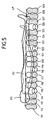
- FIG. 5 there is shown an embodiment particularly interesting of the invention and which finds application in the context alternating inflation, in English "alternating pressure mode", with a device support or mattress comprising a multitude of cushions or tubes 111, 112, 113, 114 to 129 which can be deflated alternately individually, sequentially.
- This sequential deflation can be performed one in two, one in three, or one in four as shown in Figure 4 for cushions or pillows 114, 118, 122, 126, or even one in five or one in n.
- the invention which makes it possible to find a balance of support substantially along the line of flotation, provides a decisive advantage by avoiding pressures relatively high to the different parts of the body that are detrimental to a from the point of view of care, for example in the case of skin grafts, or from a point view of comfort.
- the invention makes it possible, in fact, by obtaining a balance noticeably permanent on the waterline maintaining pressure lower than the non-vascular pressure during the phases where the tissues undergo the pressure exerted by the therapeutic surface during operation alternating or "altemating" of the type shown in FIG. 5.
Landscapes
- Health & Medical Sciences (AREA)
- Nursing (AREA)
- Life Sciences & Earth Sciences (AREA)
- Animal Behavior & Ethology (AREA)
- General Health & Medical Sciences (AREA)
- Public Health (AREA)
- Veterinary Medicine (AREA)
- Invalid Beds And Related Equipment (AREA)
- Radiation-Therapy Devices (AREA)
- Apparatus For Radiation Diagnosis (AREA)
- Length Measuring Devices With Unspecified Measuring Means (AREA)
- Measuring And Recording Apparatus For Diagnosis (AREA)
Description
- la figure 1 est une vue de profil selon la flèche A de la figure 2 d'un élément à supporter, supportant ici d'une part un patient P1 représenté en trait fort dont les caractéristiques morphologiques sont relativement plus importantes que les caractéristiques morphologiques du patient P2 représenté en trait fin, les deux patients P1 et P2 étant représentés à l'état supporté sensiblement à l'équilibre correspondant sensiblement à une ligne de flottaison prédéterminée, indiquée par le trait mixte et référencée LF ;
- la figure 2 est une vue similaire à la figure 1 mais selon la flèche B de la figure 1 ;
- la figure 3 est une vue d'un mode de réalisation actuellement préféré d'un appareil de support selon la présente invention représentant d'une part un patient P1 supporté sensiblement à l'équilibre conformément aux vues des figures 1 et 2, mais visualisant les moyens essentiels de l'invention permettant d'aboutir à un support sensiblement à l'équilibre ;
- la figure 4 représente plus précisément le circuit électronique du mode de réalisation préféré représenté à la figure 3 nécessaire à la compréhension de la présente invention ; et
- la figure 5 est une vue en coupe longitudinale représentant un autre mode de réalisation particulier dans lequel le dispositif de support comprend une multitude de boudins gonflables individuels indépendants dont on peut prévoir un dégonflage individualisé séquentiel, un sur deux, un sur trois, ou un sur quatre tel que représenté, ou un sur n.
Claims (15)
- Procédé de support d'un élément à supporter, en particulier le corps d'un patient, comprenant la prévision d'au moins un dispositif (11) de support comprenant au moins une chambre (11a) fermée ou à échappement contrôlé, souple, gonflable, ladite chambre ayant une face supérieure (12) et une face inférieure (13), des moyens de remplissage (50) ou d'évacuation (52) d'un fluide de remplissage de ladite chambre étant prévus ainsi que des moyens (21) de mesure de la distance séparant ladite face supérieure relativement à ladite face inférieure, caractérisé en ce qu'on prévoit en outre un dispositif (30) de mesure de la réaction du dispositif de support relativement aux données morphologiques de l'élément à supporter comprenant la mesure (p) de la pression dans ladite chambre à ladite distance (d) d'enfoncement mesurée, on procède à la mesure de la distance d'enfoncement de l'élément à supporter dans le dispositif de support, on mesure la réaction du dispositif de support à l'enfoncement de l'élément à supporter et on combine ces deux mesures pour amener l'élément à supporter sensiblement à l'équilibre correspondant sensiblement à une ligne de flottaison prédéterminée.
- Procédé selon la revendication 1, caractérisé en ce que la combinaison précitée de la mesure (d) de distance d'enfoncement et de la mesure de la réaction du dispositif de support comprend une sommation de ces deux valeurs.
- Procédé selon l'une des revendications 1 à 2, caractérisé en ce que la combinaison consiste en une sommation de la valeur de distance d'enfoncement et de la valeur de pression dans la chambre.
- Procédé selon l'une des revendications précédentes, caractérisé en ce que la combinaison précitée de valeur de distance d'enfoncement et de valeur de mesure de réaction est comparée à une valeur de référence caractérisant la valeur d'équilibre d'enfoncement de l'élément à supporter correspondant sensiblement à la ligne de flottaison prédéterminée dudit élément à supporter.
- Procédé selon la revendication 4, caractérisé en ce que la valeur de référence précitée prédéterminée définissant l'équilibre correspondant sensiblement à la ligne de flottaison est fixée à une valeur caractéristique des pressions optimales appliquées sur la surface corporelle en contact avec le dispositif de support, pour réaliser les performances attendues en matière de prévention ou de traitement du patient, particulièrement des complications liées à un alitement ou une immobilisation prolongée, notamment des escarres.
- Procédé selon l'une des revendications précédentes, caractérisé en ce qu'on asservit le fonctionnement du dispositif de gonflage aux résultats de la combinaison précitée de la distance d'enfoncement et de la mesure de la réaction du dispositif de support.
- Procédé selon l'une des revendications précédentes, caractérisé en ce qu'on prévoit un dispositif de support (11) ou matelas comprenant une multitude de coussins ou boudins qui peuvent être dégonflés alternativement individuellement, séquentiellement, en particulier un sur deux, un sur trois, ou un sur quatre ou même un sur n.
- Procédé selon l'une des revendications précédentes, caractérisé en ce que l'élément à supporter est le corps d'un patient, en particulier d'un patient ayant subi une greffe de peau , d'un patient porteur de lésions de la peau telles que des escarres.
- Appareil de support d'un élément à supporter, en particulier le corps d'un patient, comprenant au moins un dispositif (11) de support comprenant au moins une chambre (11a) fermée ou à échappement contrôlé, souple, gonflable, ladite chambre ayant une face supérieure (12) et une face inférieure (13), des moyens de remplissage (50) ou d'évacuation (52) d'un fluide de remplissage de ladite chambre ainsi que des moyens (20) de mesure de la distance séparant ladite face supérieure relativement à ladite face inférieure, caractérisé en ce qu'il comprend en outre un dispositif (30) de mesure de la réaction du dispositif de support relativement aux données morphologiques de l'élément à supporter comprenant un dispositif (43) de mesure de la pression dans la chambre (11a) du dispositif de support à la distance d'enfoncement mesurée, un système de commande (40) comprenant des moyens de combinaison (42) de la mesure de la distance d'enfoncement fournie par le dispositif (20) de mesure de distance et de la mesure de la réaction fournie par le dispositif de mesure de réaction (30), pour amener l'élément à supporter sensiblement à l'équilibre correspondant sensiblement à une ligne de flottaison prédéterminée.
- Appareil selon la revendication 9, caractérisé en ce que le dispositif de combinaison (42) du système de commande (40) réalise la sommation de la mesure de distance d'enfoncement avec la mesure de la réaction fournie par le dispositif de mesure de réaction.
- Appareil selon la revendication 9 ou 10, caractérisé en ce que le dispositif de combinaison (42) est relié à un dispositif de comparaison (46) qui réalise une comparaison de la valeur de combinaison fournie par le dispositif de combinaison (42) avec une valeur de référence fournie par un dispositif (45) de référence, cette valeur de référence caractérisant la valeur d'équilibre d'enfoncement de l'élément à supporter correspondant sensiblement à la ligne de flottaison prédéterminée de cet élément à supporter.
- Appareil selon la revendication 11, caractérisé en ce que la valeur de référence précitée prédéterminée et définissant l'équilibre correspondant sensiblement à la ligne de flottaison est fixée à une valeur caractéristique des pressions optimales appliquées sur la surface corporelle en contact avec le dispositif de support pour réaliser les performances attendues en matière de prévention ou de traitement du patient, particulièrement des complications liées à un alitement ou une immobilisation prolongé, notamment des escarres.
- Appareil selon l'une des revendications 9 à 12, caractérisé en ce qu'il comprend un dispositif d'asservissement (47, 48) réalisant un asservissement du fonctionnement des moyens de remplissage ou d'évacuation au résultat de la combinaison précitée de la distance d'enfoncement et de la mesure de la réaction du dispositif de support (11).
- Appareil selon l'une des revendications 9 à 13, caractérisé en ce qu'on prévoit un dispositif de support (11) ou matelas comprenant une multitude de coussins ou boudins qui peuvent être dégonflés alternativement individuellement, séquentiellement, en particulier un sur deux, un sur trois, ou un sur quatre ou même un sur n.
- Appareil selon l'une des revendications 9 à 14, caractérisé en ce que l'élément de support est un matelas supportant le corps d'un patient, en particulier d'un patient ayant subi une greffe de peau, d'un patient porteur de lésions de la peau telles que des escarres.
Applications Claiming Priority (3)
| Application Number | Priority Date | Filing Date | Title |
|---|---|---|---|
| FR9615848A FR2757377B1 (fr) | 1996-12-23 | 1996-12-23 | Procede et appareil de support d'un element a supporter, en particulier le corps d'un patient permettant un support a une ligne de flottaison predeterminee |
| FR9615848 | 1996-12-23 | ||
| PCT/FR1997/002376 WO1998027849A1 (fr) | 1996-12-23 | 1997-12-22 | Procede et appareil de support d'un element a supporter, en particulier le corps d'un patient permettant un support a une ligne de flottaison predeterminee |
Publications (3)
| Publication Number | Publication Date |
|---|---|
| EP1009263A1 EP1009263A1 (fr) | 2000-06-21 |
| EP1009263B1 EP1009263B1 (fr) | 2003-07-02 |
| EP1009263B9 true EP1009263B9 (fr) | 2004-08-04 |
Family
ID=9498997
Family Applications (1)
| Application Number | Title | Priority Date | Filing Date |
|---|---|---|---|
| EP97952969A Expired - Lifetime EP1009263B9 (fr) | 1996-12-23 | 1997-12-22 | Procede et appareil de support d'un element a supporter, en particulier le corps d'un patient permettant un support a une ligne de flottaison predeterminee |
Country Status (10)
| Country | Link |
|---|---|
| US (1) | US6009580A (fr) |
| EP (1) | EP1009263B9 (fr) |
| JP (2) | JP2001506892A (fr) |
| AT (1) | ATE243966T1 (fr) |
| AU (1) | AU5667698A (fr) |
| BR (1) | BR9714052A (fr) |
| CA (1) | CA2274951C (fr) |
| DE (1) | DE69723319T2 (fr) |
| FR (1) | FR2757377B1 (fr) |
| WO (1) | WO1998027849A1 (fr) |
Families Citing this family (47)
| Publication number | Priority date | Publication date | Assignee | Title |
|---|---|---|---|---|
| FR2751585B1 (fr) | 1996-07-24 | 2002-08-16 | Support Systems International | Produit multicouches a couche centrale electriquement conductrice utile comme element de capteur inductif |
| FR2757378B1 (fr) * | 1996-12-23 | 1999-03-12 | Support Systems International | Procede et appareil de support d'un element a supporter, en particulier le corps d'un patient, presentant un dispositif de support independant d'un dispositif de controle |
| FR2766072B1 (fr) * | 1997-07-21 | 1999-08-27 | Poly System Injection | Coussin pneumatique a cellules individuellement deformables |
| US6560804B2 (en) * | 1997-11-24 | 2003-05-13 | Kci Licensing, Inc. | System and methods for mattress control in relation to patient distance |
| AU1328400A (en) * | 1998-10-28 | 2000-05-15 | Hill-Rom, Inc. | Force optimization surface apparatus and method |
| US6721980B1 (en) | 1998-10-28 | 2004-04-20 | Hill-Fom Services, Inc. | Force optimization surface apparatus and method |
| GB2369775B (en) * | 2000-12-09 | 2003-05-28 | Huntleigh Technology Plc | Inflatable support |
| US6701559B2 (en) * | 2001-08-01 | 2004-03-09 | Aero Products International, Inc. | Increased height inflatable support system |
| US7478448B2 (en) * | 2001-08-01 | 2009-01-20 | Aero Products International, Inc. | Inflatable reinforcing chamber |
| US6530751B1 (en) * | 2001-08-23 | 2003-03-11 | Supertrend International Inc. | Device for controlling air filling and exhausting of an air cushion |
| WO2004006726A1 (fr) * | 2002-07-17 | 2004-01-22 | Aero Products International, Inc. | Systeme de support gonflable |
| EP2250987A3 (fr) * | 2004-04-30 | 2011-11-30 | Hill-Rom Services, Inc. | Support de patient |
| WO2005104904A1 (fr) * | 2004-04-30 | 2005-11-10 | Tactex Controls Inc. | Appareil de support d'un corps a regulation automatique de pression et procedes associes |
| US8090478B2 (en) | 2005-06-10 | 2012-01-03 | Hill-Rom Services, Inc. | Control for pressurized bladder in a patient support apparatus |
| WO2007016054A2 (fr) | 2005-07-26 | 2007-02-08 | Hill-Rom Services, Inc. | Systeme et procede permettant de commander un matelas pneumatique |
| DE102006032987A1 (de) * | 2006-07-17 | 2008-01-31 | Stefan Hammerschmidt | Verfahren zum Betreiben eines Lagerungssystems für Personen |
| US7849545B2 (en) | 2006-11-14 | 2010-12-14 | Hill-Rom Industries Sa | Control system for hospital bed mattress |
| JP5125219B2 (ja) * | 2007-05-15 | 2013-01-23 | 横浜ゴム株式会社 | エアーセル |
| FR2917278A1 (fr) | 2007-06-18 | 2008-12-19 | Hill Rom Ind S A Sa | Dispositif de support de type matelas comportant une structure gonflable heterogene |
| FR2920535B1 (fr) | 2007-08-30 | 2009-11-27 | Hill Rom Ind Sa | Capteur de detection et de mesure de pressions incorporant au moins une cellule resistive de detection de forces |
| FR2922439B1 (fr) * | 2007-10-18 | 2010-12-10 | Hill Rom Ind Sa | Procede de gonflage alterne d'un dispositif de support a cellules gonflables et dispositif pour sa mise en oeuvre |
| FR2924927B1 (fr) * | 2007-12-14 | 2009-12-25 | Thaddee Mulliez | Matelas gonflable anti-escarres |
| JP2009183490A (ja) * | 2008-02-06 | 2009-08-20 | Univ Of Tokyo | マット装置 |
| US8102270B2 (en) * | 2008-04-25 | 2012-01-24 | Kap Medical | Patient position apparatus and method |
| WO2010044843A1 (fr) * | 2008-10-13 | 2010-04-22 | George Papaioannou | Surface adaptable s'utilisant dans des lits et des chaises afin de réduire les escarres de décubitus |
| WO2010048112A1 (fr) * | 2008-10-24 | 2010-04-29 | Hill-Rom Services, Inc. | Appareils d'assistance et de surveillance d'une personne |
| FR2946427B1 (fr) | 2009-06-05 | 2011-09-30 | Hill Rom Ind Sa | Capteur de pression comprenant une cellule capacitive et dispositif de support en comportant. |
| US8752220B2 (en) | 2009-07-10 | 2014-06-17 | Hill-Rom Services, Inc. | Systems for patient support, monitoring and treatment |
| US20110301432A1 (en) | 2010-06-07 | 2011-12-08 | Riley Carl W | Apparatus for supporting and monitoring a person |
| US8525680B2 (en) * | 2009-09-18 | 2013-09-03 | Hill-Rom Services, Inc. | Apparatuses for supporting and monitoring a condition of a person |
| JP5562060B2 (ja) * | 2010-02-05 | 2014-07-30 | パラマウントベッド株式会社 | エアマットレス |
| JP5616076B2 (ja) * | 2010-02-05 | 2014-10-29 | パラマウントベッド株式会社 | エアマットレス |
| US8844073B2 (en) | 2010-06-07 | 2014-09-30 | Hill-Rom Services, Inc. | Apparatus for supporting and monitoring a person |
| GB201017183D0 (en) * | 2010-10-12 | 2010-11-24 | Katan Joseph M | Body support platform |
| FR2974988B1 (fr) | 2011-05-12 | 2013-06-14 | Hill Rom Ind Sa | Dispositif de regulation de l'humidite et de la temperature a la surface d'un element de support |
| WO2013077313A1 (fr) * | 2011-11-21 | 2013-05-30 | パラマウントベッド株式会社 | Matelas, procédé d'étalonnage de capteur de pression et dispositif de lit |
| US8973186B2 (en) | 2011-12-08 | 2015-03-10 | Hill-Rom Services, Inc. | Optimization of the operation of a patient-support apparatus based on patient response |
| EP2666406A3 (fr) | 2012-05-22 | 2013-12-04 | Hill-Rom Services, Inc. | Systèmes, procédés et dispositifs de prédiction de sortie d'occupant |
| US9861550B2 (en) | 2012-05-22 | 2018-01-09 | Hill-Rom Services, Inc. | Adverse condition detection, assessment, and response systems, methods and devices |
| US10219725B2 (en) * | 2012-09-04 | 2019-03-05 | Hill-Rom Services, Inc. | Patient mobility surface assessment system and method |
| US9468307B2 (en) | 2012-09-05 | 2016-10-18 | Stryker Corporation | Inflatable mattress and control methods |
| FR3000667B1 (fr) * | 2013-01-04 | 2016-05-20 | System Assist Medical | Dispositif de support pour supporter un corps, en particulier un corps humain |
| US9333136B2 (en) | 2013-02-28 | 2016-05-10 | Hill-Rom Services, Inc. | Sensors in a mattress cover |
| DK3099201T3 (da) * | 2014-01-29 | 2019-05-06 | Roho Inc | Pudenedsænkningssensor |
| US10813809B2 (en) | 2017-07-12 | 2020-10-27 | Hill-Rom Services, Inc. | Patient immersion sensor using radar |
| US10912693B2 (en) | 2017-07-12 | 2021-02-09 | Hill-Rom Services, Inc. | Patient immersion and support surface life determination using RADAR and RFID |
| US11877844B2 (en) | 2020-02-19 | 2024-01-23 | Hill-Rom Services, Inc. | Respiration detection using radar |
Family Cites Families (4)
| Publication number | Priority date | Publication date | Assignee | Title |
|---|---|---|---|---|
| NL8502789A (nl) * | 1985-10-11 | 1987-05-04 | Auping Bv | Matras. |
| US5170364A (en) * | 1990-12-06 | 1992-12-08 | Biomechanics Corporation Of America | Feedback system for load bearing surface |
| FR2718347B1 (fr) * | 1994-04-06 | 1996-06-28 | Support Systems International | Procédé et appareil de support d'un élément à supporter, en particulier le corps d'un patient permettant un support à une profondeur d'enfoncement contrôlée. |
| US5815864A (en) * | 1996-04-02 | 1998-10-06 | Sytron Corporation | Microprocessor controller and method of initializing and controlling low air loss floatation mattress |
-
1996
- 1996-12-23 FR FR9615848A patent/FR2757377B1/fr not_active Expired - Fee Related
-
1997
- 1997-12-22 CA CA002274951A patent/CA2274951C/fr not_active Expired - Fee Related
- 1997-12-22 US US08/995,183 patent/US6009580A/en not_active Expired - Lifetime
- 1997-12-22 AU AU56676/98A patent/AU5667698A/en not_active Abandoned
- 1997-12-22 EP EP97952969A patent/EP1009263B9/fr not_active Expired - Lifetime
- 1997-12-22 JP JP52847098A patent/JP2001506892A/ja active Pending
- 1997-12-22 BR BR9714052-0A patent/BR9714052A/pt not_active IP Right Cessation
- 1997-12-22 WO PCT/FR1997/002376 patent/WO1998027849A1/fr active IP Right Grant
- 1997-12-22 DE DE69723319T patent/DE69723319T2/de not_active Expired - Lifetime
- 1997-12-22 AT AT97952969T patent/ATE243966T1/de not_active IP Right Cessation
-
2007
- 2007-06-20 JP JP2007163205A patent/JP2007307393A/ja active Pending
Also Published As
| Publication number | Publication date |
|---|---|
| FR2757377B1 (fr) | 1999-03-12 |
| JP2001506892A (ja) | 2001-05-29 |
| WO1998027849A1 (fr) | 1998-07-02 |
| FR2757377A1 (fr) | 1998-06-26 |
| EP1009263B1 (fr) | 2003-07-02 |
| CA2274951C (fr) | 2006-08-15 |
| BR9714052A (pt) | 2000-05-09 |
| ATE243966T1 (de) | 2003-07-15 |
| JP2007307393A (ja) | 2007-11-29 |
| EP1009263A1 (fr) | 2000-06-21 |
| US6009580A (en) | 2000-01-04 |
| DE69723319D1 (de) | 2003-08-07 |
| CA2274951A1 (fr) | 1998-07-02 |
| DE69723319T2 (de) | 2004-04-22 |
| AU5667698A (en) | 1998-07-17 |
Similar Documents
| Publication | Publication Date | Title |
|---|---|---|
| EP1009263B1 (fr) | Procede et appareil de support d'un element a supporter, en particulier le corps d'un patient permettant un support a une ligne de flottaison predeterminee | |
| EP0959737B1 (fr) | Procede et dispositif de support d'un patient a zone talon de support derivee | |
| EP0676158B1 (fr) | Procédé et appareil de support d'un élément à supporter, en particulier le corps d'un patient permettant un enfoncement contrôlé | |
| EP0973425B1 (fr) | Procede et appareil de degonflage rapide et de vidage sensiblement total d'une chambre gonflable, en particulier une chambre d'un dispositif de support, tel qu'un matelas | |
| CA2274950C (fr) | Procede et appareil de support d'un element a supporter, en particulier le corps d'un patient, presentant un dispositif de support independant du dispositif de commande | |
| FR2751743A1 (fr) | Procede et dispositif a self integree dans un pont de mesure | |
| CA2154700C (fr) | Dispositif de regulation et de controle de l'ecoulement du liquide cephalo-rachidien dans un circuit de drainage | |
| FR2758259A1 (fr) | Procede et appareil de gonflage rapide d'une chambre gonflable, en particulier une chambre d'un dispositif de support, tel qu'un matelas | |
| ATE238724T1 (de) | Verfahren und vorrichtung zur unterstützung eines patientenkörpers, mit integriertem dynamischem und automatischem balanciersystem | |
| FR2544202A1 (fr) | Installation pour soigner les lesions thermiques par de l'air abacterien | |
| WO2006008406A1 (fr) | Dispositif de prevention d'escarre | |
| EP0918502B1 (fr) | Produit multicouche a couche centrale electriquement conductrice utile comme element de capteur inductif | |
| CA3197780A1 (fr) | Dispositif medical implantable | |
| ATE74731T1 (de) | Oszillometrische blutdruckueberwachung waehrend druckablass mittels veraenderlicher druckintervalle. | |
| FR2814062A1 (fr) | Procede et dispositif pour l'adaptation de la pression d'interface entre un patient et un support gonflable | |
| FR2707874A1 (fr) | Matelas destiné en particulier à éviter le décubitus. | |
| FR2882254A1 (fr) | Procede de regulation d'un matelas | |
| EP0302767A1 (fr) | Appareil de massage du corps par pressions cycliques | |
| EP0348297A1 (fr) | Dispositif de mesure de la tension artérielle | |
| FR3008602A1 (fr) | Dispositif de surveillance sous forme de patch |
Legal Events
| Date | Code | Title | Description |
|---|---|---|---|
| PUAI | Public reference made under article 153(3) epc to a published international application that has entered the european phase |
Free format text: ORIGINAL CODE: 0009012 |
|
| 17P | Request for examination filed |
Effective date: 19990623 |
|
| AK | Designated contracting states |
Kind code of ref document: A1 Designated state(s): AT CH DE ES FR GB IT LI NL |
|
| 17Q | First examination report despatched |
Effective date: 20010525 |
|
| GRAH | Despatch of communication of intention to grant a patent |
Free format text: ORIGINAL CODE: EPIDOS IGRA |
|
| GRAH | Despatch of communication of intention to grant a patent |
Free format text: ORIGINAL CODE: EPIDOS IGRA |
|
| GRAA | (expected) grant |
Free format text: ORIGINAL CODE: 0009210 |
|
| AK | Designated contracting states |
Designated state(s): AT CH DE ES FR GB IT LI NL |
|
| PG25 | Lapsed in a contracting state [announced via postgrant information from national office to epo] |
Ref country code: NL Free format text: LAPSE BECAUSE OF FAILURE TO SUBMIT A TRANSLATION OF THE DESCRIPTION OR TO PAY THE FEE WITHIN THE PRESCRIBED TIME-LIMIT Effective date: 20030702 Ref country code: IT Free format text: LAPSE BECAUSE OF FAILURE TO SUBMIT A TRANSLATION OF THE DESCRIPTION OR TO PAY THE FEE WITHIN THE PRESCRIBED TIME-LIMIT;WARNING: LAPSES OF ITALIAN PATENTS WITH EFFECTIVE DATE BEFORE 2007 MAY HAVE OCCURRED AT ANY TIME BEFORE 2007. THE CORRECT EFFECTIVE DATE MAY BE DIFFERENT FROM THE ONE RECORDED. Effective date: 20030702 Ref country code: AT Free format text: LAPSE BECAUSE OF FAILURE TO SUBMIT A TRANSLATION OF THE DESCRIPTION OR TO PAY THE FEE WITHIN THE PRESCRIBED TIME-LIMIT Effective date: 20030702 |
|
| REG | Reference to a national code |
Ref country code: GB Ref legal event code: FG4D Free format text: NOT ENGLISH |
|
| REG | Reference to a national code |
Ref country code: CH Ref legal event code: EP |
|
| REF | Corresponds to: |
Ref document number: 69723319 Country of ref document: DE Date of ref document: 20030807 Kind code of ref document: P |
|
| PG25 | Lapsed in a contracting state [announced via postgrant information from national office to epo] |
Ref country code: ES Free format text: LAPSE BECAUSE OF FAILURE TO SUBMIT A TRANSLATION OF THE DESCRIPTION OR TO PAY THE FEE WITHIN THE PRESCRIBED TIME-LIMIT Effective date: 20031013 |
|
| GBT | Gb: translation of ep patent filed (gb section 77(6)(a)/1977) | ||
| NLV1 | Nl: lapsed or annulled due to failure to fulfill the requirements of art. 29p and 29m of the patents act | ||
| PG25 | Lapsed in a contracting state [announced via postgrant information from national office to epo] |
Ref country code: LI Free format text: LAPSE BECAUSE OF NON-PAYMENT OF DUE FEES Effective date: 20031231 Ref country code: CH Free format text: LAPSE BECAUSE OF NON-PAYMENT OF DUE FEES Effective date: 20031231 |
|
| PLBE | No opposition filed within time limit |
Free format text: ORIGINAL CODE: 0009261 |
|
| STAA | Information on the status of an ep patent application or granted ep patent |
Free format text: STATUS: NO OPPOSITION FILED WITHIN TIME LIMIT |
|
| 26N | No opposition filed |
Effective date: 20040405 |
|
| REG | Reference to a national code |
Ref country code: CH Ref legal event code: PL |
|
| PGFP | Annual fee paid to national office [announced via postgrant information from national office to epo] |
Ref country code: GB Payment date: 20131218 Year of fee payment: 17 Ref country code: DE Payment date: 20131218 Year of fee payment: 17 |
|
| PGFP | Annual fee paid to national office [announced via postgrant information from national office to epo] |
Ref country code: FR Payment date: 20131209 Year of fee payment: 17 |
|
| REG | Reference to a national code |
Ref country code: DE Ref legal event code: R119 Ref document number: 69723319 Country of ref document: DE |
|
| GBPC | Gb: european patent ceased through non-payment of renewal fee |
Effective date: 20141222 |
|
| REG | Reference to a national code |
Ref country code: FR Ref legal event code: ST Effective date: 20150831 |
|
| PG25 | Lapsed in a contracting state [announced via postgrant information from national office to epo] |
Ref country code: GB Free format text: LAPSE BECAUSE OF NON-PAYMENT OF DUE FEES Effective date: 20141222 Ref country code: DE Free format text: LAPSE BECAUSE OF NON-PAYMENT OF DUE FEES Effective date: 20150701 |
|
| PG25 | Lapsed in a contracting state [announced via postgrant information from national office to epo] |
Ref country code: FR Free format text: LAPSE BECAUSE OF NON-PAYMENT OF DUE FEES Effective date: 20141231 |