EP1009079A1 - Vorrichtung zur Begrenzung der Temperatur einer Lichtwellen emittierenden Laser-Diode - Google Patents
Vorrichtung zur Begrenzung der Temperatur einer Lichtwellen emittierenden Laser-Diode Download PDFInfo
- Publication number
- EP1009079A1 EP1009079A1 EP99116339A EP99116339A EP1009079A1 EP 1009079 A1 EP1009079 A1 EP 1009079A1 EP 99116339 A EP99116339 A EP 99116339A EP 99116339 A EP99116339 A EP 99116339A EP 1009079 A1 EP1009079 A1 EP 1009079A1
- Authority
- EP
- European Patent Office
- Prior art keywords
- heat transfer
- laser diode
- heat
- temperature
- heat sink
- Prior art date
- Legal status (The legal status is an assumption and is not a legal conclusion. Google has not performed a legal analysis and makes no representation as to the accuracy of the status listed.)
- Granted
Links
- 239000012530 fluid Substances 0.000 claims abstract description 26
- 230000002596 correlated effect Effects 0.000 claims abstract description 4
- 239000007789 gas Substances 0.000 claims description 10
- 239000011261 inert gas Substances 0.000 claims description 10
- 239000000463 material Substances 0.000 claims description 6
- 230000001419 dependent effect Effects 0.000 claims description 5
- 230000008859 change Effects 0.000 claims description 4
- 230000006870 function Effects 0.000 claims description 3
- 238000010438 heat treatment Methods 0.000 description 6
- 238000009413 insulation Methods 0.000 description 5
- 238000000034 method Methods 0.000 description 4
- 239000000126 substance Substances 0.000 description 4
- 244000089486 Phragmites australis subsp australis Species 0.000 description 3
- 230000005494 condensation Effects 0.000 description 3
- 238000009833 condensation Methods 0.000 description 3
- 230000000875 corresponding effect Effects 0.000 description 3
- 239000007788 liquid Substances 0.000 description 3
- 239000002184 metal Substances 0.000 description 3
- 230000008901 benefit Effects 0.000 description 2
- 230000005540 biological transmission Effects 0.000 description 2
- 238000001816 cooling Methods 0.000 description 2
- 230000000694 effects Effects 0.000 description 2
- 239000000203 mixture Substances 0.000 description 2
- 230000036316 preload Effects 0.000 description 2
- 230000008569 process Effects 0.000 description 2
- 230000005855 radiation Effects 0.000 description 2
- 238000010521 absorption reaction Methods 0.000 description 1
- 230000009471 action Effects 0.000 description 1
- 238000007796 conventional method Methods 0.000 description 1
- 238000011161 development Methods 0.000 description 1
- 230000018109 developmental process Effects 0.000 description 1
- 230000010339 dilation Effects 0.000 description 1
- 239000000428 dust Substances 0.000 description 1
- 238000005265 energy consumption Methods 0.000 description 1
- 238000005516 engineering process Methods 0.000 description 1
- 239000004744 fabric Substances 0.000 description 1
- 239000007792 gaseous phase Substances 0.000 description 1
- 230000017525 heat dissipation Effects 0.000 description 1
- 239000007791 liquid phase Substances 0.000 description 1
- 229910001092 metal group alloy Inorganic materials 0.000 description 1
- 239000012188 paraffin wax Substances 0.000 description 1
Images

Classifications
-
- H—ELECTRICITY
- H01—ELECTRIC ELEMENTS
- H01S—DEVICES USING THE PROCESS OF LIGHT AMPLIFICATION BY STIMULATED EMISSION OF RADIATION [LASER] TO AMPLIFY OR GENERATE LIGHT; DEVICES USING STIMULATED EMISSION OF ELECTROMAGNETIC RADIATION IN WAVE RANGES OTHER THAN OPTICAL
- H01S5/00—Semiconductor lasers
- H01S5/02—Structural details or components not essential to laser action
- H01S5/024—Arrangements for thermal management
- H01S5/02469—Passive cooling, e.g. where heat is removed by the housing as a whole or by a heat pipe without any active cooling element like a TEC
Definitions
- the invention relates to a device for limiting the temperature of a light-emitting laser diode according to the preamble of patent claim 1 .
- the transmission of data between satellites in space is generally done optically or via light waves, preferably laser diodes for generating the light waves to be used. It is a general property of laser diodes that the frequencies the light waves they emit from the respective working temperature of the laser diodes are dependent. To ensure flawless data transmission, the respective frequency of the emitted light waves and thus also the temperature of the laser diodes be as invariant as possible.
- the laser diode is indirect, that is, over several constructive elements, in connection with a heat sink, which, for example, as Radiator be formed or consist of a component of the structure of the satellite can.
- the heat sink and the temperature of the laser diode have temperatures that can change continuously depending on external circumstances, depending on the one hand the position of the satellites both with respect to the sun and the earth as well regarding their position, and on the other hand, due to the age of the satellite, since different electronic components Work less efficiently with increasing age and therefore more Loss energy in the form of heat arises, as a result of increasing age increasing pollution with dust, which gives the satellites a darker color assume what leads to an increased absorption of UV solar radiation and thus to a Temperature increase leads.
- a constant working temperature of the laser diode is aimed for. In certain However, it can also occur - especially depending on the distance of the remote station be desired that the temperature of the laser diode takes on different values than that first mentioned working temperature.
- the procedure is as follows: the various Components are designed so that under extreme operating conditions, i.e. when the Heat sink has its maximum temperature and the heat dissipation of the laser diode is also maximum, the laser diode at its working temperature or only insignificant is below the working temperature. These conditions place those considered constant Amount of heat transferred between the laser diode and the heat sink. Under all other operating conditions, the laser diode must then use a heating device be heated so that their temperature has the required value, as a result of the constant heat transfers a higher amount of heat than required by the laser diode is transferred to the heat sink or a heat transfer takes place that is larger than is actually necessary.
- the disadvantage of this method is that of the limited amount of energy available in a satellite Part must be used to heat the laser diode and therefore not for the actual one Operation of the laser diode, i.e. for the emission of light waves, is available.
- thermo-electric cooling device for the laser diode limit the temperature of the laser diode.
- the object of the invention is thus seen in a device of the type mentioned Way of creating, with avoiding the disadvantages described above the temperature of the laser diode at a predetermined value or within a very limited area can be kept.
- heat transfer is intended to include both actual heat conduction, convection and heat transfer fall, in short all processes, through which heat from the laser diode via the heat transfer arrangement to the heat sink transforms.
- heat transfer between the laser diode and the heat sink in any case heat transfers between the different one another adjacent constructive arranged between the laser diode and the heat sink Elements, furthermore actual heat conduction and possibly convection within this includes parts as well as radiation.
- heat from the laser diode is not only given to the heat transfer arrangement but also to other elements. The each the amount of heat transferred unintentionally is proportionate small compared to the deliberately transferred amount of heat.
- the heat transfer is established anyway Passively controlled by the laser diode to the heat sink so that the temperature the laser diode remains constant. This happens because between the laser diode and the heat sink is arranged in a heat transfer arrangement and is designed that the extent of heat transfer is essentially a function of the temperature of the Laser diode, or is directly correlated with the temperature of the laser diode, such that the heat transfer at high temperature of the laser diode is great, at low temperature the Laser diode is small.
- the heat transfer arrangement has an element with variable thermal conductivity.
- elements are known per se, namely under the names VCHP ( V ariable C onductance H eat P ipe), their structure and mode of operation are briefly described below.
- Each element consists essentially of a hollow body, for example a tube which is closed on all sides, the exterior of which is provided at one end with a heat source, in the present case with the laser diode or the base of the laser diode, and at the other end connected to the heat sink.
- the hollow body contains a working fluid that occurs in a mixture of gaseous and liquid phases in the temperature range in which the element is used.
- the working fluid absorbs heat and evaporates, in the area of the heat sink, the working fluid releases heat and condenses.
- the working fluid thus flows as a gas from the area of the laser diode to the area of the heat sink and as a liquid from the area of the heat sink to the area of the laser diode.
- the heat transfer in the tube is essentially convective, and only a small part of the heat is transferred through actual heat conduction, namely in the tube walls themselves.
- the tube is preferred in the area of its wall with an insert in the form of a lattice or honeycomb-like Formed so that the working fluid due to capillary action in liquid form flows in the area of the tube wall, while the working fluid in gaseous form in the central area of the pipe flows in the opposite direction.
- the heat transfer capacity of such pipes can be influenced by making them active Volume or volume available to the working fluid changed.
- the end of the pipe, which is arranged in the area of the heat sink, is used for this purpose is formed as a gas reservoir containing inert gas. Will the tube from the diode If less heat is supplied, the inert gas expands, which increases the area in which the working fluid condenses, shrinking, whereupon less heat is transferred to the heat sink is delivered.
- the control of heat transfer using the inert gas can be further improved, if a heater for the gas reservoir is provided with the inert gas.
- the volume of the inert gas can be increased by heating and thus the heat transfer be reduced.
- the energy required for this heating is significantly lower than the energy that would have to be used to heat the laser diode to ultimately to achieve the same effect. It is obvious that the heated gas reservoir should be insulated to some extent from the heat sink.
- Suitable arrangements of elbows allow a space-saving arrangement of others Components, such as electronics.
- the heat transfer can by the heat conduction taking place in the pipe wall.
- the tube has an appropriate length, to have a corresponding thermal resistance, otherwise no sufficient Heat transfer takes place.
- the heat transfer arrangement comprises a heat transfer body with a heat transfer surface that can be two or three dimensional can, and which is pressed onto a corresponding surface of the heat sink, as well as a Biasing device that variable the heat transfer area from that to be transferred Bias heat amount of certain force on the surface of the heat sink, whereby the heat transfer between the heat transfer surface increases with increasing contact pressure and the heat sink increases.
- the pretensioner is designed that the biasing force exerted by them increases when the temperature of the laser diode increases.
- the heat transfer grain in turn receives the amount of heat to be transferred from the laser diode on a heat conduction path through heat transfer as well through heat conduction.
- the pretensioning device comprises a bellows device, which is filled with a liquid and / or gaseous substance or a mixture of substances, whose pressure is below the temperatures when using the bellows device rule, noticeably changes.
- the bellows device is designed and arranged such that this results in a prestressing force that is temperature-dependent in the required manner; at an increase in the temperature of the laser diode increases the temperature and thus that Volume of the material in the bellows, which results in a higher preload.
- the biasing device comprises a spring device with a spring made of a metal or a metal alloy with memory.
- the spring device is on the one hand with the heat source and on the other hand with that on the heat sink prestressed heat transfer body in connection.
- the arrangement of the spring device is such that a heating of the heat source has the consequence that the previously deformed spring returns to its original shape and thereby the pressure on the Heat transfer body increases.
- the respective Temperature of the laser diode correlated material properties of a metal and not one Fluids used.
- FIG. 1 shows a heat transfer arrangement 10 with a tube which is bent in the shape of a U and filled with a working fluid 11 and which is arranged between a laser diode 12 and a heat sink 14 .
- the laser diode 12 comprises a plurality of laser diode components 16 and a laser diode base plate 18 .
- the heat sink 14 is plate-shaped and arranged on a structure 20 of a satellite, not shown in the following.
- a heat insulation structure 22 is located between the laser diode base plate 18 and the heat sink 14 .
- the area of the heat transfer arrangement 10 arranged on the laser diode base plate 18 forms an evaporator zone 24, in which heat is transferred from the laser diode base plate 18 via the wall of the tube to the working fluid 11 , as a result of which the latter evaporates.
- the area of the heat transfer arrangement 10 arranged on the heat sink 14 forms a condensation zone 26 , in which heat is transferred from the working fluid 11 to the heat sink 14 via the wall of the tube, the working fluid 11 condensing .
- the tube continues in a gas reservoir 28 , in which an inert gas 29 is located.
- the gas reservoir 28 can be heated by means of a heating device (not shown) and is insulated to a certain extent against the heat sink 14 by an insulation 30 .
- the inert gas 29 expands into the tube as the temperature rises; the more volume the inert gas 29 occupies, the smaller the condensation zone 26 and the lower the heat transfer.
- the gas reservoir 28 must therefore be heated when relatively little heat has to be transferred from the laser diode 12 to the heat sink 14 .
- FIG. 2 shows an arrangement which is basically the same in structure and mode of operation, with a laser diode 12, comprising a heat transfer arrangement 10 with a gas reservoir 28 , a plurality of laser diode components 16 arranged on a base plate 18 and one Heat sink 14 .
- the heat transfer arrangement 10 contains the working fluid 11 and the gas reservoir 28 contains the inert gas 29 , which can expand into the tube forming the heat transfer arrangement 10 .
- this heat transfer arrangement 10 is not designed as a U-shaped but as an L-shaped tube.
- FIG. 3 shows a heat transfer arrangement 10 with a heat transfer body 31 , which has a heat transfer surface 33 , which is applied by means of a pretensioning device 32 with variable force shown in FIGS. 4 and 5
- Heat sink 14 or a suitable surface thereof can be prestressed; with higher pretensioning force or greater pressure, the heat transfer from the heat transfer plate 33 to the heat sink 14 increases and thus the heat transfer from the laser diode 12 to the heat sink 14 .
- the laser diode 12 has a plurality of laser diode components 16 and a base plate 18 , and the heat sink 14 is arranged on the structure 20 of the satellite, which is not shown below.
- the base plate 18 and the heat sink 14 are also connected here by a heat insulation structure 22 .
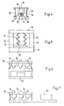
- a variant of the pretensioning device 32 is shown in more detail in FIG. 4 .
- a bellows device 34 in which a material 36, for example paraffin, is arranged, the volume of which changes markedly as a function of the temperature of the laser diode 12 .
- a stamp device 38 is arranged, with which the heat transfer plate 33 is acted upon.
- the volume of the substance 36 increases and thus the pretensioning force which the stamp device 38 exerts on the heat transfer plate 33 , so that the heat transfer increases.
- the temperature of the base plate 18 of the heat diode drops, the volume of the substance 36 and the pretensioning force of the stamp device 38 decrease, so that the heat transfer is reduced.
- Fig. 5 shows an arrangement corresponding to FIG. 4, with the base plate 18 of the laser diode and the heat sink 14 , which are connected via the heat insulation structure 22 , and with the heat transfer arrangement 10, which the Heat transfer plate 33 and the biasing device 32 comprises.
- the biasing device 32 here comprises a spring 40 made of a memory metal.
- FIG. 6 shows a device in which the heat transfer from the base plate 18 of the laser diode takes place by three parallel heat transfer arrangements 34 , which are essentially constructed according to FIG. 4 .
- the electronics 50 are arranged below the heat transfer arrangements 34 . In this way, a space-saving arrangement in the lateral direction is possible.
- FIG. 7 shows a device that is essentially the same as FIG. 6 , but the electronics 50 are arranged next to the heat transfer arrangements 34 . With such an arrangement, more space is required laterally, on the other hand, the overall height is less than in the case of the device according to FIG. 6.
Landscapes
- Physics & Mathematics (AREA)
- Condensed Matter Physics & Semiconductors (AREA)
- General Physics & Mathematics (AREA)
- Electromagnetism (AREA)
- Optics & Photonics (AREA)
- Cooling Or The Like Of Semiconductors Or Solid State Devices (AREA)
- Semiconductor Lasers (AREA)
Abstract
Description
- Fig. 1
- eine erstes Ausführungsbeispiel einer Wärme-Transfer-Anordnung, die als U-förmig gebogenes, ein Arbeits-Fluid enthaltendes Rohr ausgebildet ist, in vereinfachter Darstellung;
- Fig. 2
- eine zweites Ausführungsbeispiel einer Wärme-Transfer-Anordnung, die als L-förmig gebogenes, ein Arbeits-Fluid enthaltendes Rohr ausgebildet ist, in vereinfachter Darstellung;
- Fig. 3
- ein drittes Ausführungsbeispiel einer Wärme-Transfer-Anordnung, die eine auf eine Fläche der Wärme-Senke vorspannbare Wärmeübergangs-Fläche und eine die erforderliche Vorspannkraft erzeugende Vorspann-Einrichtung umfasst, in vereinfachter Darstellung;
- Fig. 4
- das in Fig. 3 dargestellte Ausführungsbeispiel mit einer ersten Variante der Vorspann-Einrichtung, in schematischer Darstellung;
- Fig. 5
- das in Fig. 3 dargestellte Ausführungsbeispiel mit einer zweiten Variante der Vorspann-Einrichtung, in schematischer Darstellung;
- Fig. 6
- ein erstes Ausführungsbeispiel einer Einrichtung mit mehreren parallelen Wärme-Transfer-Anordnungen gemäss Fig. 4; und
- Fig. 7
- ein zweites Ausführungsbeispiel einer Einrichtung mit mehreren parallelen Wärme-Transfer-Anordnungen gemäss Fig. 4.
Claims (10)
- Vorrichtung zur Begrenzung der Temperatur einer Lichtwellen emittierenden Laser-Diode (12) in einem Weltraum-Satelliten mittels einer Wärme-Transfer-Anordnung, durch welche Wärme von der Laser-Diode (12) zu einer Wärme-Senke (14) transferiert wird, dadurch gekennzeichnet,dass die Wärme-Transfer-Kapazität der Wärme-Transfer-Anordnung (10) direkt mit der Temperatur der Laser-Dioden (12) korreliert ist.
- Vorrichtung nach Patentanspruch 1,
dadurch gekennzeichnet,dass die Wärme-Transfer-Anordnung (10) mindestens einen vorzugsweise rohrförmigen, Hohlkörper umfasst, dessen einer Endbereich (24) mit der Laser-Diode (12) und dessen anderer Endbereich (26) mit der Wärme-Senke (14) verbunden ist, welcher Hohlkörper ein Arbeits-Fluid (11) enthält, das im Bereich der Laser-Diode (12) verdampft und im Bereich der Wärme-Senke (14) kondensiert. - Vorrichtung nach Patentanspruch 2,
dadurch gekennzeichnet,dass das für das Arbeits-Fluid (11) zur Verfügung stehende Volumen des Hohlkörpers veränderbar ist, um die Wärme-Transfer-Kapazität der Wärme-Transfer-Anordnung (10) zu verändern. - Vorrichtung nach Patentanspruch 3,
dadurch gekennzeichnet,dass zur Veränderung des für das Arbeits-Fluid (11) zur Verfügung stehenden Volumens der Hohlkörper mit einem ein Inertgas (29) enthaltenden, vorzugsweise beheizbaren und ggfs. gegen die Wärme-Senke (14) isolierten Gas-Reservoir (28) kommuniziert. - Vorrichtung nach Patentanspruch 1,
dadurch gekennzeichnet,dass die Wärme-Transfer-Anordnung (10) mindestens einen vorzugsweise plattenförmigen Wärme-Transfer-Körper (31) mit einer Wärmeübergangs-Fläche (33) und eine Vorspann-Einrichtung (32) aufweist, um die Wärmeübergangs-Fläche (33) mit von der Temperatur der Laser-Diode (12) abhängiger Kraft auf eine Fläche der Wärme-Senke (14) vorzuspannen. - Vorrichtung nach Patentanspruch 5,
dadurch gekennzeichnet,dass die Vorspann-Einrichtung (32) eine Balgeinrichtung (34) aufweist, die eine den Wärme-Transfer-Körper (31) beaufschlagenden Stempel-Einrichtung (38) und einen auf die Stempel-Einrichtung (38) wirkenden Stoff (36) enthält, dessen Volumen sich temperaturabhängig im Bereich der Temperaturen von Laser-Diode (12) und Wärme-Senke (14) merklich verändert. - Vorrichtung nach Patentanspruch 6,
dadurch gekennzeichnet,dass die Vorspann-Einrichtung (32) eine den Wärme-Transfer-Körper (31) beaufschlagende Feder-Vorrichtung mit einer Feder (40) aus einem Memory-Werkstoff aufweist. - Vorrichtung nach mindestens einem der obigen Patentansprüche,
dadurch gekennzeichnet,dass die Wärme-Transfer-Anordnung (10) so ausgebildet ist, dass sie zusammen mit weiteren konstruktiven Elementen, beispielsweise einer Elektronik (50), platzsparend zwischen der Laser-Diode (16, 18) und der Wärme-Senke (14) angeordnet ist. - Vorrichtung nach mindestens einem der obigen Patentansprüche,
dadurch gekennzeichnet,dass sie mindestens eine weitere Wärme-Transfer-Anordnung aufweist. - Vorrichtung nach Patentanspruch 9,
dadurch gekennzeichnet,dass die Wärme-Transfer-Anordnungen (10) parallel angeordnet sind.
Applications Claiming Priority (2)
| Application Number | Priority Date | Filing Date | Title |
|---|---|---|---|
| CH228398 | 1998-11-13 | ||
| CH228398 | 1998-11-13 |
Publications (2)
| Publication Number | Publication Date |
|---|---|
| EP1009079A1 true EP1009079A1 (de) | 2000-06-14 |
| EP1009079B1 EP1009079B1 (de) | 2007-08-01 |
Family
ID=4230156
Family Applications (1)
| Application Number | Title | Priority Date | Filing Date |
|---|---|---|---|
| EP99116339A Expired - Lifetime EP1009079B1 (de) | 1998-11-13 | 1999-08-19 | Vorrichtung zur Begrenzung der Temperatur einer Lichtwellen emittierenden Laser-Diode |
Country Status (5)
| Country | Link |
|---|---|
| EP (1) | EP1009079B1 (de) |
| JP (1) | JP2000150750A (de) |
| AT (1) | ATE368952T1 (de) |
| CA (1) | CA2287167A1 (de) |
| DE (1) | DE59914432D1 (de) |
Cited By (2)
| Publication number | Priority date | Publication date | Assignee | Title |
|---|---|---|---|---|
| DE102006037747A1 (de) * | 2006-08-11 | 2008-03-13 | Nokia Siemens Networks Gmbh & Co.Kg | Anordnung zur Kühlung eines elektrischen Bauelements |
| US8956021B2 (en) | 2011-09-26 | 2015-02-17 | Goodrich Lighting Systems Gmbh | Aircraft light |
Families Citing this family (1)
| Publication number | Priority date | Publication date | Assignee | Title |
|---|---|---|---|---|
| TWI384172B (zh) * | 2009-09-21 | 2013-02-01 | 和碩聯合科技股份有限公司 | 發光裝置 |
Citations (3)
| Publication number | Priority date | Publication date | Assignee | Title |
|---|---|---|---|---|
| JPS63226952A (ja) * | 1987-03-16 | 1988-09-21 | Hitachi Ltd | 半導体装置 |
| US5371753A (en) * | 1993-08-26 | 1994-12-06 | Litton Systems, Inc. | Laser diode mount |
| JPH09199882A (ja) * | 1996-01-22 | 1997-07-31 | Topcon Corp | 温度制御装置 |
-
1999
- 1999-08-19 DE DE59914432T patent/DE59914432D1/de not_active Expired - Lifetime
- 1999-08-19 AT AT99116339T patent/ATE368952T1/de not_active IP Right Cessation
- 1999-08-19 EP EP99116339A patent/EP1009079B1/de not_active Expired - Lifetime
- 1999-10-22 CA CA002287167A patent/CA2287167A1/en not_active Abandoned
- 1999-10-26 JP JP11303841A patent/JP2000150750A/ja active Pending
Patent Citations (3)
| Publication number | Priority date | Publication date | Assignee | Title |
|---|---|---|---|---|
| JPS63226952A (ja) * | 1987-03-16 | 1988-09-21 | Hitachi Ltd | 半導体装置 |
| US5371753A (en) * | 1993-08-26 | 1994-12-06 | Litton Systems, Inc. | Laser diode mount |
| JPH09199882A (ja) * | 1996-01-22 | 1997-07-31 | Topcon Corp | 温度制御装置 |
Non-Patent Citations (3)
| Title |
|---|
| PATENT ABSTRACTS OF JAPAN vol. 013, no. 023 (E - 705) 19 January 1989 (1989-01-19) * |
| PATENT ABSTRACTS OF JAPAN vol. 097, no. 011 28 November 1997 (1997-11-28) * |
| VANEVENHOVEN D E AND ANTONIAK D: "variable heat pipe technoligy for precise temperature control for the NASA/DDTL transmitter", PROCEEDINGS OF THE SPIE, THE INTERNATIONAL SOCIETY FOR OPTICAL ENGINEERING, OPTOMECHANICAL DESIGN OF LASER TRANSMITTERS AND RECIEVERS, LOS ANGELES CA, USA 16-17 JANUARI 1989, vol. 1044, pages 135 - 144, XP002099473 * |
Cited By (3)
| Publication number | Priority date | Publication date | Assignee | Title |
|---|---|---|---|---|
| DE102006037747A1 (de) * | 2006-08-11 | 2008-03-13 | Nokia Siemens Networks Gmbh & Co.Kg | Anordnung zur Kühlung eines elektrischen Bauelements |
| DE102006037747B4 (de) * | 2006-08-11 | 2009-06-04 | Nokia Siemens Networks Gmbh & Co.Kg | Anordnung zur Kühlung eines elektrischen Bauelements |
| US8956021B2 (en) | 2011-09-26 | 2015-02-17 | Goodrich Lighting Systems Gmbh | Aircraft light |
Also Published As
| Publication number | Publication date |
|---|---|
| DE59914432D1 (de) | 2007-09-13 |
| ATE368952T1 (de) | 2007-08-15 |
| CA2287167A1 (en) | 2000-05-13 |
| JP2000150750A (ja) | 2000-05-30 |
| EP1009079B1 (de) | 2007-08-01 |
Similar Documents
| Publication | Publication Date | Title |
|---|---|---|
| DE4116044C2 (de) | Wärmeübertragungsanordnung | |
| DE69424761T2 (de) | Kühlungsapparat vom Wärmerohrtyp | |
| DE2403538C3 (de) | Wärmerohr | |
| DE69606296T2 (de) | Wärmeübertragungskreislauf mit kapillaren pumpen | |
| DE69704105T2 (de) | Kapillarverdampfer für zweiphasigen kreislauf eines energieübertragungssystems zwischen einer wärmequelle und einer kältequelle | |
| DE3650658T2 (de) | Wärmetauscher | |
| DE19941398C2 (de) | Wärmeübertragungssystem und Wärmeübertragungsverfahren | |
| DE3617762A1 (de) | Mit dem kapillareffekt arbeitende waermeuebertragungs-koerper und waermeuebertragungssystem | |
| DE112019003618T5 (de) | Wärmerohre umfassend dochtstrukturen mit variabler durchlässigkeit | |
| DE69504357T2 (de) | Energieübertragungssystem zwischen einer wärmequelle und einer kältequelle | |
| DE4121534A1 (de) | Kuehlvorrichtung | |
| EP0541927B1 (de) | Verdampfungswärmetauscher | |
| DE19724020A1 (de) | Wärmestrahlungsgerät mit Wärmerohr für Energiespeicherbatteriegeräte | |
| EP0289456A1 (de) | Siegelbacke für Verpackungsmaschinen | |
| DE3441074C2 (de) | ||
| EP1009079B1 (de) | Vorrichtung zur Begrenzung der Temperatur einer Lichtwellen emittierenden Laser-Diode | |
| DE4135709C1 (de) | ||
| DE2013808A1 (de) | Zwangsdurchlauf Verdampfer einer Kompressionskalteanlage | |
| DE2614061C2 (de) | Gasgesteuerter Wärmerohr-Thermostat mit einem Kontrollgas eines Gasdruckregelsystems | |
| DE2613991C2 (de) | Therniostatische Betätigungsvorrichtung für ein Heizmittelventil | |
| DE3705103A1 (de) | Schichtwaermespeicher | |
| DE3149208C2 (de) | Steuerbares Wärmerohr | |
| DE3023094C2 (de) | Vorrichtung zum Erzeugen von Dampf | |
| DE19802670C2 (de) | Wärmeübertrager | |
| EP4067781B1 (de) | Kälteregister zur kaltlufterzeugung mit enteisungseinrichtung |
Legal Events
| Date | Code | Title | Description |
|---|---|---|---|
| PUAI | Public reference made under article 153(3) epc to a published international application that has entered the european phase |
Free format text: ORIGINAL CODE: 0009012 |
|
| AK | Designated contracting states |
Kind code of ref document: A1 Designated state(s): AT BE CH CY DE DK ES FI FR GB GR IE IT LI LU MC NL PT SE |
|
| AX | Request for extension of the european patent |
Free format text: AL;LT;LV;MK;RO;SI |
|
| 17P | Request for examination filed |
Effective date: 20000707 |
|
| AKX | Designation fees paid |
Free format text: AT BE CH CY DE DK ES FI FR GB GR IE IT LI LU MC NL PT SE |
|
| GRAP | Despatch of communication of intention to grant a patent |
Free format text: ORIGINAL CODE: EPIDOSNIGR1 |
|
| RAP1 | Party data changed (applicant data changed or rights of an application transferred) |
Owner name: OERLIKON SPACE AG |
|
| GRAS | Grant fee paid |
Free format text: ORIGINAL CODE: EPIDOSNIGR3 |
|
| GRAA | (expected) grant |
Free format text: ORIGINAL CODE: 0009210 |
|
| AK | Designated contracting states |
Kind code of ref document: B1 Designated state(s): AT BE CH CY DE DK ES FI FR GB GR IE IT LI LU MC NL PT SE |
|
| REG | Reference to a national code |
Ref country code: GB Ref legal event code: FG4D Free format text: NOT ENGLISH |
|
| REG | Reference to a national code |
Ref country code: CH Ref legal event code: NV Representative=s name: OK PAT AG PATENTE MARKEN LIZENZEN Ref country code: CH Ref legal event code: EP |
|
| REG | Reference to a national code |
Ref country code: IE Ref legal event code: FG4D Free format text: LANGUAGE OF EP DOCUMENT: GERMAN |
|
| REF | Corresponds to: |
Ref document number: 59914432 Country of ref document: DE Date of ref document: 20070913 Kind code of ref document: P |
|
| ET | Fr: translation filed | ||
| PG25 | Lapsed in a contracting state [announced via postgrant information from national office to epo] |
Ref country code: NL Free format text: LAPSE BECAUSE OF FAILURE TO SUBMIT A TRANSLATION OF THE DESCRIPTION OR TO PAY THE FEE WITHIN THE PRESCRIBED TIME-LIMIT Effective date: 20070801 Ref country code: FI Free format text: LAPSE BECAUSE OF FAILURE TO SUBMIT A TRANSLATION OF THE DESCRIPTION OR TO PAY THE FEE WITHIN THE PRESCRIBED TIME-LIMIT Effective date: 20070801 Ref country code: ES Free format text: LAPSE BECAUSE OF FAILURE TO SUBMIT A TRANSLATION OF THE DESCRIPTION OR TO PAY THE FEE WITHIN THE PRESCRIBED TIME-LIMIT Effective date: 20071112 |
|
| NLV1 | Nl: lapsed or annulled due to failure to fulfill the requirements of art. 29p and 29m of the patents act | ||
| GBV | Gb: ep patent (uk) treated as always having been void in accordance with gb section 77(7)/1977 [no translation filed] |
Effective date: 20070801 |
|
| REG | Reference to a national code |
Ref country code: IE Ref legal event code: FD4D |
|
| PG25 | Lapsed in a contracting state [announced via postgrant information from national office to epo] |
Ref country code: MC Free format text: LAPSE BECAUSE OF NON-PAYMENT OF DUE FEES Effective date: 20070831 Ref country code: GR Free format text: LAPSE BECAUSE OF FAILURE TO SUBMIT A TRANSLATION OF THE DESCRIPTION OR TO PAY THE FEE WITHIN THE PRESCRIBED TIME-LIMIT Effective date: 20071102 Ref country code: DK Free format text: LAPSE BECAUSE OF FAILURE TO SUBMIT A TRANSLATION OF THE DESCRIPTION OR TO PAY THE FEE WITHIN THE PRESCRIBED TIME-LIMIT Effective date: 20070801 |
|
| PG25 | Lapsed in a contracting state [announced via postgrant information from national office to epo] |
Ref country code: PT Free format text: LAPSE BECAUSE OF FAILURE TO SUBMIT A TRANSLATION OF THE DESCRIPTION OR TO PAY THE FEE WITHIN THE PRESCRIBED TIME-LIMIT Effective date: 20080102 Ref country code: IE Free format text: LAPSE BECAUSE OF FAILURE TO SUBMIT A TRANSLATION OF THE DESCRIPTION OR TO PAY THE FEE WITHIN THE PRESCRIBED TIME-LIMIT Effective date: 20070801 Ref country code: GB Free format text: LAPSE BECAUSE OF FAILURE TO SUBMIT A TRANSLATION OF THE DESCRIPTION OR TO PAY THE FEE WITHIN THE PRESCRIBED TIME-LIMIT Effective date: 20070801 |
|
| PLBE | No opposition filed within time limit |
Free format text: ORIGINAL CODE: 0009261 |
|
| STAA | Information on the status of an ep patent application or granted ep patent |
Free format text: STATUS: NO OPPOSITION FILED WITHIN TIME LIMIT |
|
| PG25 | Lapsed in a contracting state [announced via postgrant information from national office to epo] |
Ref country code: SE Free format text: LAPSE BECAUSE OF FAILURE TO SUBMIT A TRANSLATION OF THE DESCRIPTION OR TO PAY THE FEE WITHIN THE PRESCRIBED TIME-LIMIT Effective date: 20071101 |
|
| 26N | No opposition filed |
Effective date: 20080506 |
|
| PG25 | Lapsed in a contracting state [announced via postgrant information from national office to epo] |
Ref country code: AT Free format text: LAPSE BECAUSE OF NON-PAYMENT OF DUE FEES Effective date: 20070819 |
|
| PG25 | Lapsed in a contracting state [announced via postgrant information from national office to epo] |
Ref country code: CY Free format text: LAPSE BECAUSE OF FAILURE TO SUBMIT A TRANSLATION OF THE DESCRIPTION OR TO PAY THE FEE WITHIN THE PRESCRIBED TIME-LIMIT Effective date: 20070801 |
|
| PG25 | Lapsed in a contracting state [announced via postgrant information from national office to epo] |
Ref country code: LU Free format text: LAPSE BECAUSE OF NON-PAYMENT OF DUE FEES Effective date: 20070819 |
|
| REG | Reference to a national code |
Ref country code: FR Ref legal event code: PLFP Year of fee payment: 18 |
|
| REG | Reference to a national code |
Ref country code: DE Ref legal event code: R082 Ref document number: 59914432 Country of ref document: DE Representative=s name: RACH, WERNER, DIPL.-CHEM. DR.RER.NAT., DE Ref country code: DE Ref legal event code: R081 Ref document number: 59914432 Country of ref document: DE Owner name: OEI OPTO AG, CH Free format text: FORMER OWNER: OERLIKON SPACE AG, ZUERICH, CH |
|
| REG | Reference to a national code |
Ref country code: CH Ref legal event code: PUE Owner name: OEI OPTO AG, CH Free format text: FORMER OWNER: OERLIKON SPACE AG, CH |
|
| PGFP | Annual fee paid to national office [announced via postgrant information from national office to epo] |
Ref country code: IT Payment date: 20160822 Year of fee payment: 18 Ref country code: DE Payment date: 20160816 Year of fee payment: 18 Ref country code: CH Payment date: 20160812 Year of fee payment: 18 |
|
| PGFP | Annual fee paid to national office [announced via postgrant information from national office to epo] |
Ref country code: FR Payment date: 20160712 Year of fee payment: 18 |
|
| REG | Reference to a national code |
Ref country code: FR Ref legal event code: TP Owner name: OEI OPTO AG, CH Effective date: 20161104 Ref country code: FR Ref legal event code: CD Owner name: OEI OPTO AG, CH Effective date: 20161104 |
|
| PGFP | Annual fee paid to national office [announced via postgrant information from national office to epo] |
Ref country code: BE Payment date: 20160624 Year of fee payment: 18 |
|
| REG | Reference to a national code |
Ref country code: CH Ref legal event code: NV Representative=s name: TROESCH SCHEIDEGGER WERNER AG, CH |
|
| REG | Reference to a national code |
Ref country code: DE Ref legal event code: R119 Ref document number: 59914432 Country of ref document: DE |
|
| REG | Reference to a national code |
Ref country code: CH Ref legal event code: PL |
|
| PG25 | Lapsed in a contracting state [announced via postgrant information from national office to epo] |
Ref country code: LI Free format text: LAPSE BECAUSE OF NON-PAYMENT OF DUE FEES Effective date: 20170831 Ref country code: CH Free format text: LAPSE BECAUSE OF NON-PAYMENT OF DUE FEES Effective date: 20170831 |
|
| REG | Reference to a national code |
Ref country code: FR Ref legal event code: ST Effective date: 20180430 |
|
| REG | Reference to a national code |
Ref country code: BE Ref legal event code: PD Owner name: OEI OPTO AG; CH Free format text: DETAILS ASSIGNMENT: CHANGE OF OWNER(S), AFFECTATION / CESSION; FORMER OWNER NAME: RUAG SCHWEIZ AG Effective date: 20160811 Ref country code: BE Ref legal event code: MM Effective date: 20170831 Ref country code: BE Ref legal event code: HC Owner name: RUAG SPACE AG; CH Free format text: DETAILS ASSIGNMENT: CHANGE OF OWNER(S), CHANGEMENT NOM PROPRIETAIRE; FORMER OWNER NAME: OERLIKON SPACE AG Effective date: 20160811 |
|
| PG25 | Lapsed in a contracting state [announced via postgrant information from national office to epo] |
Ref country code: DE Free format text: LAPSE BECAUSE OF NON-PAYMENT OF DUE FEES Effective date: 20180301 |
|
| PG25 | Lapsed in a contracting state [announced via postgrant information from national office to epo] |
Ref country code: IT Free format text: LAPSE BECAUSE OF NON-PAYMENT OF DUE FEES Effective date: 20170819 Ref country code: FR Free format text: LAPSE BECAUSE OF NON-PAYMENT OF DUE FEES Effective date: 20170831 Ref country code: BE Free format text: LAPSE BECAUSE OF NON-PAYMENT OF DUE FEES Effective date: 20170831 |