EP1008155B1 - Magnetic assembly for a transformer or the like - Google Patents
Magnetic assembly for a transformer or the like Download PDFInfo
- Publication number
- EP1008155B1 EP1008155B1 EP98914346A EP98914346A EP1008155B1 EP 1008155 B1 EP1008155 B1 EP 1008155B1 EP 98914346 A EP98914346 A EP 98914346A EP 98914346 A EP98914346 A EP 98914346A EP 1008155 B1 EP1008155 B1 EP 1008155B1
- Authority
- EP
- European Patent Office
- Prior art keywords
- series
- laminations
- assembly
- magnetic assembly
- relation
- Prior art date
- Legal status (The legal status is an assumption and is not a legal conclusion. Google has not performed a legal analysis and makes no representation as to the accuracy of the status listed.)
- Expired - Lifetime
Links
Images

Classifications
-
- H—ELECTRICITY
- H01—ELECTRIC ELEMENTS
- H01F—MAGNETS; INDUCTANCES; TRANSFORMERS; SELECTION OF MATERIALS FOR THEIR MAGNETIC PROPERTIES
- H01F27/00—Details of transformers or inductances, in general
- H01F27/24—Magnetic cores
- H01F27/245—Magnetic cores made from sheets, e.g. grain-oriented
Definitions
- This invention relates to laminated magnetic assemblies such as may be employed in transformers or other electrical apparatus.
- laminations made of sheets of ferrous material are employed in various electrical apparatus and provide a magnetic path.
- the laminations provide a magnetic path around an electric current developed in a winding or other electrical conductor.
- the laminated assembly In some uses, as when the laminated assembly is employed as an electric sensor core in an overload relay and is required to respond linearly at low currents and continue a linear output throughout the desired current range while having an adequate high saturation level, the laminated assembly requires a large cross sectional area with minimal air gaps. Conventionally, this has been achieved through the use of laminations of relatively thin, sheets of ferrous material configured generally in the form of a "U” or a "D". The laminations are achieved by "U-U” or "D-U” laminations stacked in a sequence. This type of construction tends to require extra width on the ends of the laminations to compensate for the air gaps left between groups of laminations.
- the laminations are riveted together or adhesively assembled using varnish or epoxy resin, or even held together with spring clips. If the extra width is not permitted because of spatial requirements of a given use, then two laminations are used per layer so as to minimize the air gap. However, as the extra width is eliminated and the assembly becomes narrower, it becomes increasingly difficult to utilize rivets to secure the laminations together. Moreover, as the assembly becomes thicker, spring clips lose their effectiveness and the use of varnish and/or epoxy as an adhesive tends to be messy and time consuming. As a consequence, magnetic assemblies made up of laminations for use in transformers and the like have either been bulky, i.e. undesirably large, with a consequence that the volume of the equipment in which they are employed is increased or, if of an appropriate size matched to the requisite magnetic efficiency for the particular use, undesirably expensive to fabricate.
- the present invention is directed to providing a compact magnetic assembly of the type that may be used in a transformer and which is economical to manufacture.
- EP-A2-0 353 029 discloses a first pack and a second pack of complementary laminations to make a core of an electromagnetic device, the first and second packs of laminations fit together and are held together by resilient or permanent deformations.
- first surfaces face one another while the second surfaces face oppositely of one another.
- one of the first and second surfaces is concave and the other of the first and second surfaces is convex.
- first and second surfaces are generally parallel to one another.
- the first and fourth series of laminations have the same configuration and the second and third series of laminations have the same configuration.
- the first and third series are assembled in abutting relation and the second and fourth series are in abutting relation to minimize the existence of significant air gaps.
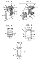
- FIG. 1, 2, 4 and 5 An exemplary embodiment of a magnetic assembly for use in, for example, a sensing core transformer as employed in an overload relay, is illustrated in Figs. 1, 2, 4 and 5. The same is seen to include a first lamination assembly, generally designated 10, a second lamination assembly, generally designated 12 and abutted to one side of the lamination assembly 10, and an electrical coil assembly, generally designated 14 mounted thereto.
- a sensing core transformer another conductor will typically be employed as, for example, a conventional bus bar (not shown) disposed to extend through the lamination assemblies 10 and 12 in a conventional fashion.
- the coil assembly 14 is conventional and includes a bobbin 16 made of a conventional insulating material as, for example, a plastic.
- An electrical conductor 18 is wound about the bobbin 16 to form an electrical coil.
- the lamination assembly 10 is made up of a series of U-shaped laminations 20 having opposed, generally parallel legs 22 and 24 connected by a bight 26. As a result, a central open area 28 is defined. As illustrated, the open area 28 has a somewhat enlarged upper end 30. As can be seen in Fig. 1, the bobbin 16 is impaled on the leg 24 and is such is to substantially fill the central area 28 except for the enlarged area 30. The latter is reserved for the bus bar (not shown) mentioned earlier.
- the legs 22, 24 terminate in facing concave surfaces 32 and 34 respectively.
- the ends of the legs 22 and 24 are also provided with notches 36 for purposes to be disclosed.
- a second series of laminations 38 which, with the first series 20, defines a closed loop of the ferrous material.
- the laminations 38 terminate in oppositely directed convex surfaces 40 and 42 which are complimentary with and engage the surfaces 32 and 34 as best seen in Fig. 4.
- the second lamination assembly 12 also includes a series of generally U-shaped laminations 50 having an open central area 28 with an enlarged open end 30 as before.
- the open area 28 may be dosed by a fourth series of laminations 52 which bridges the legs 54, 56 of the laminations 50 again to form a closed loop of the ferrous material.
- the distance between the facing surfaces 32 and 34 of the lamination assembly 10 is slightly less than the distance between the opposed, oppositely directed surfaces 40, 42 of the laminations 38. Typically, the difference in distance will be on the order of 0.51 mm (0.020 inches). This provides a means whereby when the surface 32 is abutted to the surface 40 and the surface 34 is abutted to the surface 42, an interference fit will result to hold the laminations 38 assembled to the laminations 20.
- partial perfing or stake locking To hold individual laminations 20 in assembled and aligned relation, they are typically held by a construction known as partial perfing or stake locking.
- An example of stake locking is illustrated in Fig. 3 and the endmost lamination 60 in a stack includes an opening 62.
- the adjacent laminations 64, 66, 68 and 70 all have respective perforations displaced into the adjacent lamination.
- the lamination 64 has a perforation 72 displaced into the opening 62 while the lamination 66 includes a perforation 74 displaced into the perforation 72.
- the lamination 68 includes a perforation 76 displaced into perforation 74 while the lamination 70 includes a perforation 78 displaced into the perforation 76.
- Equipment for forming the partial perforations or stake holding structure may be obtained, for example, from Swanbro Corporation of Elk Grove Village, Illinois or L.H. Carbide of Fort Wayne, Indiana.
- the laminations 50 making up the part of the second lamination assembly 12 are assembled together, and to the laminations 20 making up part of the first lamination assembly 10 and are all held in place by locking means of the sort just described at locations such as illustrated at 80. Similar structure, also shown at 80, may be used to fasten the laminations 52 to one another and to the laminations 38.
- the legs 22 and 24 of the first lamination assembly 10 may be spread slightly by placing a tool in the notches 36 and applying an expanding force thereto. This allows that part of the lamination assembly 10 made up of the laminations 38 and that part of the lamination assembly 12 made up of the laminations 52 to be inserted laterally in place after, of course, the winding assembly 14 has been impaled on the lamination assemblies. When the expanding force applied to the notches 36 is released, an interference fit results.
- the configuration of the laminations 20 is different from that of laminations 50, which in tum is different from that of the laminations 38, which in turn is different from that of laminations 52.
- the laminations 38 When assembled, the laminations 38 will be generally aligned with the laminations 52 while the laminations 20 will be aligned with the laminations 50.
- the air gaps that are present can be adjusted to set the system for a range of amperage that is desired for the particular piece of equipment with which the cores are to be used.
- FIG. 6-12 A further, and highly preferred embodiment is illustrated in Figs. 6-12, inclusive.
- the coil assembly 14 is again employed and includes the bobbin 16 along with an electrical winding 18 thereon.
- Two lamination assemblies, generally designated 100 and 102, are employed in this embodiment of the invention. Each is made up of a plurality of laminations 104 that are interferenced fitted in assembled relation with a plurality of laminations 106. As illustrated, the number of laminations employed in each of the assemblies 100 and 102 is the same and as with all the laminations, each is made up of a thin sheet of ferrous material, usually steel. However, on some instances, a different number of lamination, and/or differing thickness of the assemblies 100 and 102 may be used to develop particular magnetic characteristics.
- Each of the assemblies 100 and 102 in turn is made up of a series of the laminations 104 together with a series of the laminations 106.
- the configuration of the laminations 104 is shown in Fig. 9 and is basically that of a shallow U-shape having a central bight 110 flanked by legs 112 and 114.
- the legs 112 and 114 have facing, generally parallel surfaces 116 and 118 respectively.
- the space between the legs 112 and 114 defines a central open area 120 as seen in Fig. 11 and which may be closed off by assembly of the laminations 106 to the laminations 104 as illustrated in Fig. 11 to form a closed loop of magnetic material.
- the open area of 120 has an enlarged upper end 122 for receipt of a bus bar or the like while the remainder of the open area 112 receives one part of the bobbin 16.
- Each lamination 106 is also somewhat U-shaped but in this case, the two legs 124 are located somewhat closer to one another than the legs 112 and dimensioned so that they nest within the legs 112 and 114.
- the legs 124 and 126 have oppositely facing, generally parallel surfaces 128 and 130 that are adapted to interference fit with the surfaces 116 and 118 on the legs 112 and 114 of the laminations 104.
- the surfaces 128 and 130 are approximately 0.020 inches further apart than the surfaces 116 and 118 to achieve the desired interference fit.
- each of the laminations 106 is extended somewhat past the legs 124 and 126 to provide extensions 134 and 136 which, together with the outer surfaces of the legs 112 and 114, form a rectangular peripheral shape as seen in Figs. 11 and 12.
- Fig. 11 illustrates how the laminations 104 and 106 are arranged to provide the first lamination assembly 100 while Fig. 12 illustrates the arrangement of the laminations 104 and 106 to form the second lamination assembly 102.
- the outer most corners of the legs 124 and 126 may be slightly chamfered as at 140.
- a similar chamfer 142 may be located on the inner comers of the legs 112 and 114 to aid in assembly so that the legs 112, 114 may be cammed somewhat apart by the legs 124 and 126 to achieve the desired interference fit between the surfaces 116 and 128 and the surfaces 118 and 130.
- stake holding formations as shown at 144 and generally as described in connection with the first embodiment are used as a holding means. They are not only used to hold the laminations 104 and the laminations 106 in abutting relation to each other, but also may be used at the interface of the assemblies 100 and 102 to hold them in assembled relation as well.
- Figs. 6-12 is a preferred embodiment in the sense that only two different lamination configurations are required, that is, only the lamination shapes of the laminations 104 and 106 are needed. In contrast, four different lamination shapes are required for the embodiment of Figs. 1-5, which in turn means it is more expensive to tool.
- overlaps to control air gap losses are achieved simply by making the laminations 104 and 106 of a different configuration but then reversing their side to side arrangement as they are stacked by abutting the assembly 100 to the assembly 102 as illustrated in the drawings.
- a core for a transformer or the like made according to the invention can be made of relatively small size. Wide parts of the laminations heretofore required so as to allow the laminations to be assembled by rivets are avoided.
- the use of the stake holding means to assemble the individual laminations in a given series to one another also provides a means of eliminating other securing methods such as spring clips or adhesives heretofore employed.
- the use of an interference fit to secure lamination parts to one another to define a closed loop of ferrous material which is at least partially occupied by the coil provides a further means whereby conventional fastening methods may be avoided.
- the unique structures and methods employed result in a sensing coil of economical construction and yet of relatively small bulk so that it may be readily and advantageously incorporated in electrical apparatus requiring small size.
- the unique arrangement of laminations of differing configurations allows one to control air gaps within the overall assembly to achieve a desired magnetic effectiveness, dependent upon the ultimate use to which the sensing cores are to be put.
Landscapes
- Engineering & Computer Science (AREA)
- Power Engineering (AREA)
- Coils Or Transformers For Communication (AREA)
- Manufacturing Cores, Coils, And Magnets (AREA)
Applications Claiming Priority (3)
| Application Number | Priority Date | Filing Date | Title |
|---|---|---|---|
| US83890597A | 1997-04-11 | 1997-04-11 | |
| US838905 | 1997-04-11 | ||
| PCT/US1998/006201 WO1998047158A1 (en) | 1997-04-11 | 1998-03-30 | Magnetic assembly for a transformer or the like |
Publications (2)
| Publication Number | Publication Date |
|---|---|
| EP1008155A1 EP1008155A1 (en) | 2000-06-14 |
| EP1008155B1 true EP1008155B1 (en) | 2003-09-03 |
Family
ID=25278359
Family Applications (1)
| Application Number | Title | Priority Date | Filing Date |
|---|---|---|---|
| EP98914346A Expired - Lifetime EP1008155B1 (en) | 1997-04-11 | 1998-03-30 | Magnetic assembly for a transformer or the like |
Country Status (7)
| Country | Link |
|---|---|
| US (1) | US6060978A (ja) |
| EP (1) | EP1008155B1 (ja) |
| JP (2) | JP4322965B2 (ja) |
| KR (1) | KR100516908B1 (ja) |
| CN (1) | CN1143329C (ja) |
| DE (1) | DE69817837T2 (ja) |
| WO (1) | WO1998047158A1 (ja) |
Families Citing this family (11)
| Publication number | Priority date | Publication date | Assignee | Title |
|---|---|---|---|---|
| US6911886B2 (en) * | 2003-08-08 | 2005-06-28 | General Electric Company | Flux coil system |
| US7656267B2 (en) | 2005-04-28 | 2010-02-02 | Tyco Electronics Corporation | Electrical transformers and assemblies |
| US7803140B2 (en) * | 2005-07-06 | 2010-09-28 | Icu Medical, Inc. | Medical connector with closeable male luer |
| JP3121577U (ja) * | 2006-03-02 | 2006-05-18 | 株式会社スマート | 偏心磁性体コイルシステム |
| US20070262839A1 (en) * | 2006-05-09 | 2007-11-15 | Spang & Company | Electromagnetic assemblies, core segments that form the same, and their methods of manufacture |
| EP2260494B1 (de) * | 2008-04-10 | 2013-03-20 | Siemens Aktiengesellschaft | Transformatorkern |
| JP5406126B2 (ja) | 2010-06-09 | 2014-02-05 | 株式会社岡本工作機械製作所 | インゴットブロックの複合面取り加工装置および加工方法 |
| US8276279B2 (en) | 2010-08-09 | 2012-10-02 | Wahl Clipper Corporation | Hair clipper with a vibrator motor |
| CN104376985A (zh) * | 2014-12-12 | 2015-02-25 | 绵阳市容富电子科技有限公司 | 网络变压装置 |
| US11592496B2 (en) * | 2017-08-01 | 2023-02-28 | Hyperion Sensors Inc. | Optical sensing methods and systems for transformers, and the construction thereof |
| EP3769324B1 (en) | 2018-04-23 | 2023-08-30 | Siemens Energy Global GmbH & Co. KG | Transformer cores and assembly methods thereof for high efficiency and high anti-corrosion performance |
Family Cites Families (9)
| Publication number | Priority date | Publication date | Assignee | Title |
|---|---|---|---|---|
| DE219466C (ja) * | ||||
| FR514079A (fr) * | 1920-04-19 | 1921-03-02 | Joseph Armand Marie Vincent De | Mode de construction des carcasses de transformateurs électriques et appareils analogues |
| DE1638944A1 (de) * | 1967-02-09 | 1970-05-14 | Waasner B | Kernblech mit zwei Blechteilen |
| DE1638943A1 (de) * | 1967-02-09 | 1970-04-23 | Waasner B | Mehrteiliger Blechkern fuer eine elektrische Vorrichtung |
| JPS58153314A (ja) * | 1982-03-06 | 1983-09-12 | Toyo Denso Co Ltd | 閉磁路型イグニシヨンコイル用鉄心 |
| JPS6376407A (ja) * | 1986-09-19 | 1988-04-06 | Tokyo Electric Co Ltd | 電磁機器 |
| ATE129357T1 (de) * | 1988-07-27 | 1995-11-15 | Linton & Hirst Ltd | Blechlamellen. |
| US4897916A (en) * | 1988-08-29 | 1990-02-06 | Coils, Inc. | Method for making a tranformer core assembly |
| US4827237A (en) * | 1988-08-29 | 1989-05-02 | Coils, Inc. | Transformer core assembly |
-
1998
- 1998-03-30 KR KR10-1999-7008922A patent/KR100516908B1/ko not_active IP Right Cessation
- 1998-03-30 EP EP98914346A patent/EP1008155B1/en not_active Expired - Lifetime
- 1998-03-30 WO PCT/US1998/006201 patent/WO1998047158A1/en active IP Right Grant
- 1998-03-30 CN CNB988041049A patent/CN1143329C/zh not_active Expired - Fee Related
- 1998-03-30 DE DE69817837T patent/DE69817837T2/de not_active Expired - Lifetime
- 1998-03-30 JP JP54394198A patent/JP4322965B2/ja not_active Expired - Fee Related
- 1998-12-21 US US09/217,551 patent/US6060978A/en not_active Expired - Lifetime
-
2006
- 2006-12-20 JP JP2006342778A patent/JP2007123928A/ja not_active Withdrawn
Also Published As
| Publication number | Publication date |
|---|---|
| KR20010005848A (ko) | 2001-01-15 |
| CN1252159A (zh) | 2000-05-03 |
| KR100516908B1 (ko) | 2005-09-23 |
| US6060978A (en) | 2000-05-09 |
| CN1143329C (zh) | 2004-03-24 |
| WO1998047158A1 (en) | 1998-10-22 |
| JP4322965B2 (ja) | 2009-09-02 |
| EP1008155A1 (en) | 2000-06-14 |
| DE69817837D1 (de) | 2003-10-09 |
| JP2007123928A (ja) | 2007-05-17 |
| JP2001520804A (ja) | 2001-10-30 |
| DE69817837T2 (de) | 2004-07-29 |
Similar Documents
| Publication | Publication Date | Title |
|---|---|---|
| JP2007123928A (ja) | 変圧器などの磁気組立体 | |
| EP0557378B1 (en) | A power supply circuit with integrated magnetic components | |
| US5534839A (en) | Miniature transformer | |
| US7646281B2 (en) | Snap-together choke and transformer assembly for an electric arc welder | |
| US5703559A (en) | Plate packet for magnet cores for use in inductive components having a longitudinal opening | |
| US7623016B2 (en) | Snap together multiple phase inductor assembly | |
| EP0439410A2 (en) | Laminate for magnetic core | |
| US5349742A (en) | Method of making a secondary for use in induction motors | |
| GB2035707A (en) | An ignition coil for motor vehicles | |
| EP0213862A3 (en) | Magnet assembly for magnetic resonance imaging and method of manufacture | |
| US20060244562A1 (en) | Electrical Transformers and assemblies | |
| US6784781B1 (en) | Reactor and ballast system | |
| US3646493A (en) | Magnetic circuit for an inductor or transformer | |
| US4875277A (en) | Formed metal core blocking method | |
| JP2005072160A (ja) | アモルファス鉄心変圧器及び三相五脚巻鉄心変圧器 | |
| TW231358B (en) | Low-noise planar transformer | |
| WO1997005632A1 (en) | Bobbin assembled transformers | |
| GB2132416A (en) | Electromagnetic actuator | |
| JPH09115739A (ja) | 電磁装置 | |
| JPH1083923A (ja) | コア装置 | |
| JPH0334899Y2 (ja) | ||
| JPH07118423B2 (ja) | 変圧器 | |
| JPH0655229U (ja) | インダクタ及びこれに使用されるコアホルダー | |
| JPH1140432A (ja) | リアクトル用鉄心 | |
| JPS6118455Y2 (ja) |
Legal Events
| Date | Code | Title | Description |
|---|---|---|---|
| PUAI | Public reference made under article 153(3) epc to a published international application that has entered the european phase |
Free format text: ORIGINAL CODE: 0009012 |
|
| 17P | Request for examination filed |
Effective date: 19990913 |
|
| AK | Designated contracting states |
Kind code of ref document: A1 Designated state(s): DE FR GB IT |
|
| GRAH | Despatch of communication of intention to grant a patent |
Free format text: ORIGINAL CODE: EPIDOS IGRA |
|
| GRAS | Grant fee paid |
Free format text: ORIGINAL CODE: EPIDOSNIGR3 |
|
| GRAA | (expected) grant |
Free format text: ORIGINAL CODE: 0009210 |
|
| AK | Designated contracting states |
Kind code of ref document: B1 Designated state(s): DE FR GB IT |
|
| REG | Reference to a national code |
Ref country code: GB Ref legal event code: FG4D |
|
| REF | Corresponds to: |
Ref document number: 69817837 Country of ref document: DE Date of ref document: 20031009 Kind code of ref document: P |
|
| ET | Fr: translation filed | ||
| PLBE | No opposition filed within time limit |
Free format text: ORIGINAL CODE: 0009261 |
|
| STAA | Information on the status of an ep patent application or granted ep patent |
Free format text: STATUS: NO OPPOSITION FILED WITHIN TIME LIMIT |
|
| 26N | No opposition filed |
Effective date: 20040604 |
|
| REG | Reference to a national code |
Ref country code: GB Ref legal event code: 732E Free format text: REGISTERED BETWEEN 20110602 AND 20110608 |
|
| REG | Reference to a national code |
Ref country code: FR Ref legal event code: TP |
|
| PG25 | Lapsed in a contracting state [announced via postgrant information from national office to epo] |
Ref country code: DE Free format text: LAPSE BECAUSE OF NON-PAYMENT OF DUE FEES Effective date: 20111001 |
|
| PGFP | Annual fee paid to national office [announced via postgrant information from national office to epo] |
Ref country code: FR Payment date: 20120327 Year of fee payment: 15 |
|
| PGFP | Annual fee paid to national office [announced via postgrant information from national office to epo] |
Ref country code: DE Payment date: 20110520 Year of fee payment: 14 |
|
| PGFP | Annual fee paid to national office [announced via postgrant information from national office to epo] |
Ref country code: GB Payment date: 20120312 Year of fee payment: 15 Ref country code: IT Payment date: 20120328 Year of fee payment: 15 |
|
| REG | Reference to a national code |
Ref country code: DE Ref legal event code: R119 Ref document number: 69817837 Country of ref document: DE Effective date: 20121002 |
|
| GBPC | Gb: european patent ceased through non-payment of renewal fee |
Effective date: 20130330 |
|
| REG | Reference to a national code |
Ref country code: FR Ref legal event code: ST Effective date: 20131129 |
|
| PG25 | Lapsed in a contracting state [announced via postgrant information from national office to epo] |
Ref country code: FR Free format text: LAPSE BECAUSE OF NON-PAYMENT OF DUE FEES Effective date: 20130402 Ref country code: GB Free format text: LAPSE BECAUSE OF NON-PAYMENT OF DUE FEES Effective date: 20130330 |
|
| PG25 | Lapsed in a contracting state [announced via postgrant information from national office to epo] |
Ref country code: IT Free format text: LAPSE BECAUSE OF NON-PAYMENT OF DUE FEES Effective date: 20130330 |