EP1007264B1 - Stromdüse - Google Patents
Stromdüse Download PDFInfo
- Publication number
- EP1007264B1 EP1007264B1 EP98945237A EP98945237A EP1007264B1 EP 1007264 B1 EP1007264 B1 EP 1007264B1 EP 98945237 A EP98945237 A EP 98945237A EP 98945237 A EP98945237 A EP 98945237A EP 1007264 B1 EP1007264 B1 EP 1007264B1
- Authority
- EP
- European Patent Office
- Prior art keywords
- welding
- starting material
- deep drilling
- drilling
- contact tip
- Prior art date
- Legal status (The legal status is an assumption and is not a legal conclusion. Google has not performed a legal analysis and makes no representation as to the accuracy of the status listed.)
- Expired - Lifetime
Links
- 239000000463 material Substances 0.000 claims description 28
- 238000005553 drilling Methods 0.000 claims description 23
- 238000003466 welding Methods 0.000 claims description 16
- 238000000034 method Methods 0.000 claims description 11
- 238000005520 cutting process Methods 0.000 claims description 4
- 239000011343 solid material Substances 0.000 claims description 3
- 229910052751 metal Inorganic materials 0.000 claims description 2
- 239000002184 metal Substances 0.000 claims description 2
- 239000007858 starting material Substances 0.000 claims 5
- 238000004519 manufacturing process Methods 0.000 description 9
- 229910045601 alloy Inorganic materials 0.000 description 6
- 239000000956 alloy Substances 0.000 description 6
- 238000010438 heat treatment Methods 0.000 description 3
- 239000011265 semifinished product Substances 0.000 description 3
- RYGMFSIKBFXOCR-UHFFFAOYSA-N Copper Chemical compound [Cu] RYGMFSIKBFXOCR-UHFFFAOYSA-N 0.000 description 2
- 229910052802 copper Inorganic materials 0.000 description 2
- 239000010949 copper Substances 0.000 description 2
- 239000012530 fluid Substances 0.000 description 2
- 230000001050 lubricating effect Effects 0.000 description 2
- 230000005540 biological transmission Effects 0.000 description 1
- 230000001419 dependent effect Effects 0.000 description 1
- 239000003792 electrolyte Substances 0.000 description 1
- 238000005516 engineering process Methods 0.000 description 1
- 238000011010 flushing procedure Methods 0.000 description 1
- 238000005242 forging Methods 0.000 description 1
- 239000007789 gas Substances 0.000 description 1
- 239000011261 inert gas Substances 0.000 description 1
- 238000004663 powder metallurgy Methods 0.000 description 1
- 239000000047 product Substances 0.000 description 1
- 230000001681 protective effect Effects 0.000 description 1
- 239000002994 raw material Substances 0.000 description 1
- 230000008646 thermal stress Effects 0.000 description 1
- 230000007704 transition Effects 0.000 description 1
- 229910052726 zirconium Inorganic materials 0.000 description 1
Images

Classifications
-
- B—PERFORMING OPERATIONS; TRANSPORTING
- B23—MACHINE TOOLS; METAL-WORKING NOT OTHERWISE PROVIDED FOR
- B23K—SOLDERING OR UNSOLDERING; WELDING; CLADDING OR PLATING BY SOLDERING OR WELDING; CUTTING BY APPLYING HEAT LOCALLY, e.g. FLAME CUTTING; WORKING BY LASER BEAM
- B23K9/00—Arc welding or cutting
- B23K9/24—Features related to electrodes
- B23K9/28—Supporting devices for electrodes
- B23K9/282—Electrode holders not supplying shielding means to the electrode
Definitions
- the invention relates to a manufacturing method for a Contact tip for welding and cutting torches with one or several inner openings for guiding and contacting one or several welding wires.
- a protective gas welding torch is known from EP 41 165 A1 with such a contact tip, which is called contact tube there is.
- This component is at the top of the Inert gas welding torch fastens and guides the welding wire to the place where the arc begins. simultaneously the relatively high welding current through the contact tip Welding wire fed.
- the contact tip is therefore due to the Current flow and thermal stress high Exposed to loads, so far for their manufacture drawn copper material was used, being as an alloy et al Electrolyte copper and copper-chrome-zirconium as hollow Semi-finished material are used.
- the means of production or devices and the manufacturing process itself for them drawn materials are very expensive, so that there are only a few Vendors on the market give what is in corresponding Reflects material costs.
- Another disadvantage is that for every special nominal diameter and for every tolerance range Custom-made products are required. This is particularly disadvantageous for small quantities.
- the main disadvantage of drawn material is that Change in material properties due to heat treatment and reshaping. Due to the change in structure as a result of Heat treatment and the forming processes become the surfaces and wear properties of the inner opening negative affected.
- GB 1 359 875 A is a contact tip for welding or Cutting torch with one or more internal openings for Guiding and contacting a welding wire known, wherein the inner opening is made of rod-shaped primary material.
- the contact tips are manufactured using powder metallurgy.
- the present invention has the object based on a method for the inexpensive production of Specify contact tips.
- this object is achieved by a method for the production of a contact tip, in which the at least one Internal opening is made by deep drilling in the primary material.
- Embodiments of the invention are the subject of Dependent claims.
- Deep drilling is characterized by the use of Tools that allow lubricating and drilling fluid to the drill tip and the removal of the chips force. Deep drilling also comes with a high Drilling speed worked, i.e. they are small Chip dimensions generated, which thanks to constant chip evacuation Allow continuous drilling.
- the peculiarity of this process is the pressure flushing, where the lubricating and drilling fluid along the Drilling tool - within a given groove - to the front guided and the resulting small drill chips to the rear be dissipated.
- the chips are so small that they run along them can flow along the predetermined groove.
- Combined with specially developed tools can be Deep drilling accuracies in the range from IT 6 to IT 9 in Dependence on the material in one operation without Achieve post-treatment.
- the invention ensures that compared to the state technology, much cheaper material can be purchased can.
- the choice of materials is also wide in the range of alloys quasi infinite, so that the contact tips as a whole are cheaper to produce. Because that Manufacturing method according to the invention regardless of Drawability of the material is, and thus a larger Range of materials can be used as this was previously possible can also meet very special requirements the material will be considered more. For example, it cannot or hard-to-pull material can be used or also Material that is not or only with difficulty as a hollow profile (Nozzle tube) can be produced. As a raw material, both Solid material as well as pipe material are used.
- alloys with a greater degree of freedom with regard to the microstructure, the Heat treatment, the pre-forming history or the Use material history. So a material can be chosen be that regarding the wear resistance and the Power transmission is optimal.
- Materials or semi-finished products can be used with the previous manufacturing process (drawing process) not editable were.
- the alloys according to the invention are now available in contrast to the state of the art no longer have to be able to be drawn in this semi-finished form. So alloys can now can be used for contact tips that were previously used for this Were not suitable.
- Deep drilling also improves the properties of the Semi-finished product is not significantly affected, so this Properties can be calculated or predicted or stay.
- Another advantage is that in one step achieved surface quality and the improved tolerance. This improved tolerance causes that when welding over the a defined current transition throughout the area of the contact tip is present and that a much better mechanical Leadership is achieved, which in turn leads to less electrical, thermal and finally mechanical Wear leads.
- Such a contact tip is preferably produced by having a rod-shaped or rod-shaped material desired alloy and a desired outer diameter clamped in a deep drilling machine known per se and then from the primary material by deep drilling the one or more Internal openings created.
- a deep drilling machine known per se and then from the primary material by deep drilling the one or more Internal openings created.
- the contact tip 1 according to FIG. 1 is, as is usually the case, cylindrical, the tip somewhat conical can be made running.
- a Thread provided with which the contact tip in the welding or Cutting torch is fitted.
- the contact tip has in this Embodiment a continuous inner opening 2, which at its has a chamfer on the back so that the welding wire can shrink better.
- Such welding nozzles are of shape prior art.
- New is that the inner opening 2 by means of deep drilling one made of solid material or of tube material Semi-finished product was produced. This allows compared to the previous one Drawing pipes or parts that were already hollow, a much larger choice of materials.
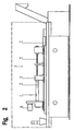
- Figure 2 shows schematically a deep drilling machine 3, the essential components of the drive 4, the drill 5, the Clamping device 6 and the feed 7 are.
- Drill 5 are used thanks to their special Design and the high speeds of manufacture smaller Shavings allow through the oil back flush be carried away so that continuous operation is achieved and the inner opening in one step in the desired high quality is produced.
Landscapes
- Engineering & Computer Science (AREA)
- Physics & Mathematics (AREA)
- Plasma & Fusion (AREA)
- Mechanical Engineering (AREA)
- Arc Welding In General (AREA)
- Drilling Tools (AREA)
Description
- Figur 1
- eine mittels des erfindungsgemäßer Verfahrens hergestellte Stromdüse und
- Figur 2
- eine Tiefbohrmaschine.
Claims (5)
- Verfahren zur Herstellung einer Stromdüse (1) für Schweißoder Schneidbrenner mit einer oder mehreren Innenöffnungen (2) zur Führung und Kontaktierung eines oder mehrerer Schweißdrähte, dadurch gekennzeichnet, daß die wenigstens eine Innenöffnung (2) durch Tiefbohren in stabförmiges Vormaterial hergestellt ist.
- Verfahren nach Anspruch 1, dadurch gekennzeichnet, daß das Vormaterial Vollmaterial oder Rohrmaterial ist.
- Verfahren nach Anspruch 1 oder Anspruch 2, dadurch gekennzeichnet, daß als Vormaterial nicht oder schwer ziehfähiges Material verwendet wird.
- Verfahren nach einem der Ansprüche, dadurch gekennzeichnet, dass das Vormaterial eine Metallstange ist.
- Verfahren nach einem der vorhergehenden Ansprüche, dadurch gekennzeichnet, dass das Vormaterial in eine Tiefbohrmaschine (3) eingespannt ist.
Applications Claiming Priority (3)
| Application Number | Priority Date | Filing Date | Title |
|---|---|---|---|
| DE19737934A DE19737934C1 (de) | 1997-08-30 | 1997-08-30 | Stromdüse |
| DE19737934 | 1997-08-30 | ||
| PCT/EP1998/005138 WO1999011417A1 (de) | 1997-08-30 | 1998-08-13 | Stromdüse |
Publications (2)
| Publication Number | Publication Date |
|---|---|
| EP1007264A1 EP1007264A1 (de) | 2000-06-14 |
| EP1007264B1 true EP1007264B1 (de) | 2003-06-11 |
Family
ID=7840699
Family Applications (1)
| Application Number | Title | Priority Date | Filing Date |
|---|---|---|---|
| EP98945237A Expired - Lifetime EP1007264B1 (de) | 1997-08-30 | 1998-08-13 | Stromdüse |
Country Status (7)
| Country | Link |
|---|---|
| US (1) | US6429406B1 (de) |
| EP (1) | EP1007264B1 (de) |
| JP (1) | JP2001514080A (de) |
| CN (1) | CN1138607C (de) |
| DE (2) | DE19737934C1 (de) |
| ES (1) | ES2201532T3 (de) |
| WO (1) | WO1999011417A1 (de) |
Families Citing this family (8)
| Publication number | Priority date | Publication date | Assignee | Title |
|---|---|---|---|---|
| JP4676698B2 (ja) * | 2001-11-07 | 2011-04-27 | エムアイジー ファースト プロプライアティー リミテッド | 改良した消耗電極アーク溶接 |
| JP4676467B2 (ja) * | 2007-09-10 | 2011-04-27 | 有限会社 星製作所 | ガスシールド消耗電極式アーク溶接装置の電極チップ再生方法及び装置 |
| US8338753B2 (en) | 2010-04-30 | 2012-12-25 | Lincoln Global, Inc. | Contact tip and diffuser |
| US9193005B2 (en) | 2011-11-02 | 2015-11-24 | Illinois Tool Works Inc. | Contact tip with contoured bore |
| CN102728939A (zh) * | 2012-06-19 | 2012-10-17 | 沈阳大学 | 窄间隙埋弧焊焊枪 |
| DE202013102979U1 (de) | 2013-07-05 | 2013-07-16 | Dinse Gmbh | Schweißbrenner für das Lichtbogen-Schutzgasschweißen und Kontaktrohr für einen solchen Schweißbrenner |
| CN112171031A (zh) * | 2020-09-15 | 2021-01-05 | 常州特尔玛枪嘴有限公司 | 一种导电嘴及其复合棒材及制造工艺 |
| DE102025106950B3 (de) | 2025-02-24 | 2026-04-30 | IBB Industrie Beteiligung und Beratung GmbH & Co. KG | Verfahren zur Herstellung einer Schweißdüse |
Family Cites Families (16)
| Publication number | Priority date | Publication date | Assignee | Title |
|---|---|---|---|---|
| GB1359875A (en) | 1971-10-22 | 1974-07-10 | Klees H D | Contact nozzles for welding machines |
| US4393565A (en) * | 1980-05-09 | 1983-07-19 | Wilson Welding Company, Inc. | Method of making a water-cooled electrode holder |
| US4342878A (en) * | 1980-05-09 | 1982-08-03 | Wilson Welding Company, Inc. | Water-cooled electrode holder |
| DE3019966A1 (de) * | 1980-05-24 | 1981-12-03 | Industrie-Werke Karlsruhe Augsburg AG Zweigniederlassung Keller & Knappich Augsburg, 8900 Augsburg | Brenner fuer das schutzgasschweissen |
| US4575612A (en) * | 1981-04-09 | 1986-03-11 | Robert Prunier | Arc welding guide tube with non-adhesive tip |
| DE3304996A1 (de) * | 1983-02-04 | 1984-08-09 | Rolf 5909 Burbach Schönau | Stromduese |
| US4490898A (en) * | 1983-04-08 | 1985-01-01 | Wilson Welding Company, Inc. | Method of repairing a water-cooled electrode holder |
| DE3427072A1 (de) | 1984-07-23 | 1986-01-30 | Melchior, Martin Theodor, 6639 Rehlingen | Schweissstrom-kontaktduese |
| SE8500714L (sv) * | 1985-02-15 | 1986-05-12 | Esab Ab | Kontaktmunstycke med en skruvlinjeformig passage for en smeltbar svetstrad |
| CH664719A5 (fr) * | 1985-11-22 | 1988-03-31 | Charmilles Technologies | Organe de contact pour fil-electrode pour electroerosion. |
| US4706679A (en) * | 1986-01-27 | 1987-11-17 | Westinghouse Electric Corp. | Disposable monitor for an EEG head set |
| EP0399334A3 (de) | 1989-05-23 | 1991-02-06 | Matsushita Electric Industrial Co., Ltd. | Verfahren zum Herstellen von Kontaktspitzen |
| DE4217995C2 (de) | 1992-05-31 | 1994-03-17 | Hendrik Danneil | Schmelzschweißkontaktdüse |
| DE4410370A1 (de) | 1994-03-25 | 1995-09-28 | Carl Cloos Schweistechnik Gmbh | Stromkontaktdüse für Schweißpistolen |
| AU7403694A (en) * | 1994-07-19 | 1996-02-16 | American Plating Systems, Inc. | Electrolytic plating apparatus and method |
| JPH0881723A (ja) | 1994-09-16 | 1996-03-26 | Mitani Shindo Kk | クロム銅および溶接機用コンタクトチップ・キャップチップ |
-
1997
- 1997-08-30 DE DE19737934A patent/DE19737934C1/de not_active Expired - Lifetime
-
1998
- 1998-08-13 CN CNB988085259A patent/CN1138607C/zh not_active Expired - Lifetime
- 1998-08-13 ES ES98945237T patent/ES2201532T3/es not_active Expired - Lifetime
- 1998-08-13 JP JP2000508502A patent/JP2001514080A/ja active Pending
- 1998-08-13 DE DE59808711T patent/DE59808711D1/de not_active Expired - Lifetime
- 1998-08-13 WO PCT/EP1998/005138 patent/WO1999011417A1/de not_active Ceased
- 1998-08-13 EP EP98945237A patent/EP1007264B1/de not_active Expired - Lifetime
- 1998-08-13 US US09/485,757 patent/US6429406B1/en not_active Expired - Lifetime
Also Published As
| Publication number | Publication date |
|---|---|
| US6429406B1 (en) | 2002-08-06 |
| WO1999011417A1 (de) | 1999-03-11 |
| JP2001514080A (ja) | 2001-09-11 |
| CN1268079A (zh) | 2000-09-27 |
| DE59808711D1 (de) | 2003-07-17 |
| EP1007264A1 (de) | 2000-06-14 |
| ES2201532T3 (es) | 2004-03-16 |
| DE19737934C1 (de) | 1998-12-10 |
| CN1138607C (zh) | 2004-02-18 |
Similar Documents
| Publication | Publication Date | Title |
|---|---|---|
| DE3601385C2 (de) | ||
| DE4415091C1 (de) | Verfahren und Vorrichtung zum kontinuierlichen, spanlosen profilierenden Zerteilen von rohrförmigen Werkstücken in einzelne, untereinander gleiche Ringe | |
| EP1572402B1 (de) | Sinterrohlinge mit gewendelten kühlkanälen | |
| EP3271101B1 (de) | Verfahren zur herstellung eines stators bzw. zur bearbeitung der innenwandung eines stators | |
| DE10334373A1 (de) | Verfahren und Vorrichtung zum Schneiden und Entgraten von Rohren, insbesondere Kunststoff- und Papprohren | |
| EP3349931B1 (de) | Spanneinrichtung zum fixieren eines werkzeugs in einer werkzeugmaschine, sowie verfahren zur herstellung der spanneinrichtung | |
| EP1007264B1 (de) | Stromdüse | |
| DE102019135404A1 (de) | Spiralbohrer mit einer stufenstrukturierten Schneidspitze | |
| EP1042086B1 (de) | Verfahren zur herstellung eines bohrwerkzeugs für werkzeugmaschinen | |
| DE2936298A1 (de) | Elektroerosive bearbeitungsmaschine | |
| DE4123859C2 (de) | Verfahren zur spanenden Bearbeitung von Werkstücken mit rotationssymmetrischen Flächen, vorzugsweise von Kurbelwellen, und Vorrichtung zur Durchführung eines solchen Verfahrens | |
| DE102010014085B4 (de) | Verfahren zum Bruchtrennen von Werkstücken und Werkstück | |
| DE10103292B4 (de) | Elektrodenführung für Erodiermaschinen sowie Verfahren zum Erodieren von Werkstücken | |
| EP1518631B1 (de) | Verfahren zur Formgebung und/oder zum mechanischen Entfernen von Ablagerungen, insbesondere von Ablagerungen an Schweisselektroden für das Widerstandsschweissen | |
| EP0634959B1 (de) | Verfahren und vorrichtung zur kontinuierlichen herstellung von zylindrischen stäben mit zumindest einem innenliegenden, wendelförmigen kanal, und nach diesem verfahren hergestellter sinterrohling | |
| DE19580446B4 (de) | Vorrichtung zum Herstellen von Profil-Werkstücken, insbesondere Zahnrädern | |
| DE2512854A1 (de) | Verfahren zur spanlosen herstellung von werkstuecken, wie z.b. spiralbohrern o.dgl., mit innenliegenden offenen kuehlkanaelen | |
| DE10260136A1 (de) | Strangpressverfahren und nach diesem Verfahren hergestellter Sinterrohling bzw. Werkzeugkörper | |
| DE2136985B2 (de) | Verfahren zur Herstellung von Bohrer-Rohlingen mit spiraligen Bohrnuten | |
| EP4149710B1 (de) | Zuführvorrichtung zum zuführen von schweisszusatzelementen für einen auftragschweissprozess, positionierhülse, entsprechende bearbeitungseinheit und verfahren | |
| EP1234626A2 (de) | Drehmaschine zur spanabhebenden Innenbearbeitung von hohlen Werkstücken | |
| EP3332900A1 (de) | Verfahren sowie werkzeugmaschine zum spanenden bearbeiten eines werkstücks | |
| DE3314830C2 (de) | ||
| DE3145883C3 (de) | Elektrisches Stauchverfahren und Vorrichtung zu dessen Durchführung | |
| DE3540890A1 (de) | Verfahren zum herstellen von einzelzahnraedern aus einer zahnradstange und spannzange zu seiner durchfuehrung |
Legal Events
| Date | Code | Title | Description |
|---|---|---|---|
| PUAI | Public reference made under article 153(3) epc to a published international application that has entered the european phase |
Free format text: ORIGINAL CODE: 0009012 |
|
| 17P | Request for examination filed |
Effective date: 20000115 |
|
| AK | Designated contracting states |
Kind code of ref document: A1 Designated state(s): BE DE ES FR GB IT NL |
|
| 17Q | First examination report despatched |
Effective date: 20020123 |
|
| GRAH | Despatch of communication of intention to grant a patent |
Free format text: ORIGINAL CODE: EPIDOS IGRA |
|
| GRAH | Despatch of communication of intention to grant a patent |
Free format text: ORIGINAL CODE: EPIDOS IGRA |
|
| GRAA | (expected) grant |
Free format text: ORIGINAL CODE: 0009210 |
|
| AK | Designated contracting states |
Designated state(s): BE DE ES FR GB IT NL |
|
| REG | Reference to a national code |
Ref country code: GB Ref legal event code: FG4D Free format text: NOT ENGLISH |
|
| GBT | Gb: translation of ep patent filed (gb section 77(6)(a)/1977) | ||
| REF | Corresponds to: |
Ref document number: 59808711 Country of ref document: DE Date of ref document: 20030717 Kind code of ref document: P |
|
| REG | Reference to a national code |
Ref country code: ES Ref legal event code: FG2A Ref document number: 2201532 Country of ref document: ES Kind code of ref document: T3 |
|
| ET | Fr: translation filed | ||
| PLBE | No opposition filed within time limit |
Free format text: ORIGINAL CODE: 0009261 |
|
| STAA | Information on the status of an ep patent application or granted ep patent |
Free format text: STATUS: NO OPPOSITION FILED WITHIN TIME LIMIT |
|
| 26N | No opposition filed |
Effective date: 20040312 |
|
| REG | Reference to a national code |
Ref country code: FR Ref legal event code: PLFP Year of fee payment: 19 |
|
| REG | Reference to a national code |
Ref country code: FR Ref legal event code: PLFP Year of fee payment: 20 |
|
| PGFP | Annual fee paid to national office [announced via postgrant information from national office to epo] |
Ref country code: NL Payment date: 20170821 Year of fee payment: 20 |
|
| PGFP | Annual fee paid to national office [announced via postgrant information from national office to epo] |
Ref country code: ES Payment date: 20170928 Year of fee payment: 20 Ref country code: DE Payment date: 20170831 Year of fee payment: 20 Ref country code: IT Payment date: 20170828 Year of fee payment: 20 Ref country code: FR Payment date: 20170822 Year of fee payment: 20 Ref country code: GB Payment date: 20170822 Year of fee payment: 20 |
|
| PGFP | Annual fee paid to national office [announced via postgrant information from national office to epo] |
Ref country code: BE Payment date: 20170821 Year of fee payment: 20 |
|
| REG | Reference to a national code |
Ref country code: DE Ref legal event code: R071 Ref document number: 59808711 Country of ref document: DE |
|
| REG | Reference to a national code |
Ref country code: NL Ref legal event code: MK Effective date: 20180812 |
|
| REG | Reference to a national code |
Ref country code: GB Ref legal event code: PE20 Expiry date: 20180812 |
|
| REG | Reference to a national code |
Ref country code: BE Ref legal event code: MK Effective date: 20180813 |
|
| PG25 | Lapsed in a contracting state [announced via postgrant information from national office to epo] |
Ref country code: GB Free format text: LAPSE BECAUSE OF EXPIRATION OF PROTECTION Effective date: 20180812 |
|
| REG | Reference to a national code |
Ref country code: ES Ref legal event code: FD2A Effective date: 20200721 |
|
| PG25 | Lapsed in a contracting state [announced via postgrant information from national office to epo] |
Ref country code: ES Free format text: LAPSE BECAUSE OF EXPIRATION OF PROTECTION Effective date: 20180814 |