EP1004841A2 - Wasserkasten für Wärmetauscher - Google Patents
Wasserkasten für Wärmetauscher Download PDFInfo
- Publication number
- EP1004841A2 EP1004841A2 EP99123593A EP99123593A EP1004841A2 EP 1004841 A2 EP1004841 A2 EP 1004841A2 EP 99123593 A EP99123593 A EP 99123593A EP 99123593 A EP99123593 A EP 99123593A EP 1004841 A2 EP1004841 A2 EP 1004841A2
- Authority
- EP
- European Patent Office
- Prior art keywords
- tank body
- tank
- side walls
- plate
- end plate
- Prior art date
- Legal status (The legal status is an assumption and is not a legal conclusion. Google has not performed a legal analysis and makes no representation as to the accuracy of the status listed.)
- Granted
Links
- 229910052751 metal Inorganic materials 0.000 claims abstract description 27
- 239000002184 metal Substances 0.000 claims abstract description 27
- 238000005219 brazing Methods 0.000 claims description 38
- 238000003466 welding Methods 0.000 claims description 32
- 229910052782 aluminium Inorganic materials 0.000 claims description 19
- XAGFODPZIPBFFR-UHFFFAOYSA-N aluminium Chemical compound [Al] XAGFODPZIPBFFR-UHFFFAOYSA-N 0.000 claims description 19
- 238000004891 communication Methods 0.000 claims description 8
- 239000012530 fluid Substances 0.000 claims description 8
- 239000000945 filler Substances 0.000 claims description 5
- 230000002093 peripheral effect Effects 0.000 claims description 5
- 238000003825 pressing Methods 0.000 claims description 2
- 238000000034 method Methods 0.000 description 26
- 230000004048 modification Effects 0.000 description 18
- 238000012986 modification Methods 0.000 description 18
- 230000008569 process Effects 0.000 description 16
- 238000005260 corrosion Methods 0.000 description 12
- 230000007797 corrosion Effects 0.000 description 12
- 239000000463 material Substances 0.000 description 12
- 229920001971 elastomer Polymers 0.000 description 9
- 239000005060 rubber Substances 0.000 description 9
- 238000004519 manufacturing process Methods 0.000 description 5
- 238000010276 construction Methods 0.000 description 4
- 230000004907 flux Effects 0.000 description 4
- 230000009972 noncorrosive effect Effects 0.000 description 4
- 230000015572 biosynthetic process Effects 0.000 description 2
- 239000000498 cooling water Substances 0.000 description 2
- 230000005540 biological transmission Effects 0.000 description 1
- 238000007796 conventional method Methods 0.000 description 1
- 239000002826 coolant Substances 0.000 description 1
- 238000001816 cooling Methods 0.000 description 1
- 230000008878 coupling Effects 0.000 description 1
- 238000010168 coupling process Methods 0.000 description 1
- 238000005859 coupling reaction Methods 0.000 description 1
- 238000007730 finishing process Methods 0.000 description 1
- 230000013011 mating Effects 0.000 description 1
- 239000004033 plastic Substances 0.000 description 1
- 229920003023 plastic Polymers 0.000 description 1
- 238000004080 punching Methods 0.000 description 1
- 230000009467 reduction Effects 0.000 description 1
- 238000009966 trimming Methods 0.000 description 1
- 238000005406 washing Methods 0.000 description 1
Images










Classifications
-
- F—MECHANICAL ENGINEERING; LIGHTING; HEATING; WEAPONS; BLASTING
- F28—HEAT EXCHANGE IN GENERAL
- F28F—DETAILS OF HEAT-EXCHANGE AND HEAT-TRANSFER APPARATUS, OF GENERAL APPLICATION
- F28F9/00—Casings; Header boxes; Auxiliary supports for elements; Auxiliary members within casings
- F28F9/001—Casings in the form of plate-like arrangements; Frames enclosing a heat exchange core
- F28F9/002—Casings in the form of plate-like arrangements; Frames enclosing a heat exchange core with fastening means for other structures
-
- F—MECHANICAL ENGINEERING; LIGHTING; HEATING; WEAPONS; BLASTING
- F28—HEAT EXCHANGE IN GENERAL
- F28F—DETAILS OF HEAT-EXCHANGE AND HEAT-TRANSFER APPARATUS, OF GENERAL APPLICATION
- F28F9/00—Casings; Header boxes; Auxiliary supports for elements; Auxiliary members within casings
- F28F9/02—Header boxes; End plates
- F28F9/0219—Arrangements for sealing end plates into casing or header box; Header box sub-elements
- F28F9/0224—Header boxes formed by sealing end plates into covers
-
- F—MECHANICAL ENGINEERING; LIGHTING; HEATING; WEAPONS; BLASTING
- F28—HEAT EXCHANGE IN GENERAL
- F28F—DETAILS OF HEAT-EXCHANGE AND HEAT-TRANSFER APPARATUS, OF GENERAL APPLICATION
- F28F9/00—Casings; Header boxes; Auxiliary supports for elements; Auxiliary members within casings
- F28F9/02—Header boxes; End plates
- F28F9/0246—Arrangements for connecting header boxes with flow lines
Definitions
- the present invention relates in general to heat exchangers of motor vehicles, and more particularly to a tank of the heat exchangers, which generally comprises a tank body of clad metal, a pipe member of clad metal, a header plate member of clad metal and end plates of clad metal which are all hermetically secured to one another by means of brazing.
- a conventional tank of heat exchanger which is disclosed in Japanese Utility Model First Provisional Publication 60-2195.
- the conventional tank comprises a tank body 1 which has a pipe inserting opening 1a provided by means of a burring reamer.
- a pipe member 2 is inserted into the pipe inserting opening 1a having its leading end abutting on an inner surface of the tank body 1 through a seating plate 3.
- usage of the seating plate 3 brings about a troublesome and time consuming work for producing the tank.
- the tank needs a height "H" much greater than the diameter "D" of the pipe member 2, which causes a bulky construction of the tank.
- FIG. 42 there is shown another conventional tank of heat exchanger.
- the conventional tank comprises a tank body 1 produced by using a deep drawing technique, and a header plate member 4 brazed to the tank body 1.
- the header plate member 4 is partially fixed or welded to the tank body 1 before carrying out the brazing.
- different types of dies are needed depending on sizes and types of the tank produced by the deep drawing technique, and thus cost of the tank increases inevitably.
- the tank is designed for radiators, the tank is obliged to have a larger height and longer structure making the deep drawing much difficult.
- the longer structure of the tank makes the brazing between the tank body 1 and the header plate member 4 much difficult.
- the parts 1 and 4 have to have complicated engaging and engaged portions 1a and 4a which are to be mutually engaged, which also brings about increase in production cost of the tank.
- FIG. 43 there is shown still another conventional tank of heat exchanger, which is of a seam welded pipe type made of aluminum.
- the tank shown in Fig. 42 has a rectangular cross section.
- this conventional tank due to the tubular shape, formation of the opening in the tank for receiving and holding the pipe member needs a troublesome and consuming manual work.
- a further conventional tank of heat exchanger which is made of aluminum.
- the tank shown in the drawings comprises an aluminum tank body 1 having a generally C-shaped cross section and an aluminum header plate member 5 fitted to an open portion of the tank body 1.
- each end plate 6 is formed with a rectangular recess 6a into which the corresponding end of the unit is press-fitted.
- the recess 6a of the end plate 6 and the end of the unit are brazed at "R" in a furnace.
- the tank body 1 becomes deformed as is shown by phantom lines. Of course, in this case, brazing of such deformed portion and the end plate is not adequately carried out.
- the radiator 7 comprises upper and lower tanks 8 and 9 of plastics and a core structure 10 interposed between the upper and lower tanks 8 and 9.
- the lower tank 9 has at its lower surface mounting pins 11 by which the lower mount rubber 12 is held.
- the lower mount rubber 12 is held by a lower bracket 13 extending from the vehicle body.
- the upper tank 8 has at its upper surface mounting pins 14 by which the upper mount rubber 15 is held.
- the upper mount rubber 15 is held by an upper bracket 16 extending from the vehicle body.
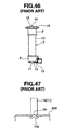
- Fig. 47 shows a conventional technique for fixing each mounting pin 14 or 11 to the upper or lower tank 8 or 9.
- the tank 8 or 9 is formed with an opening 8a
- each mounting pin 14 or 11 is formed with a forked projected portion 14a.
- the forked projected portion 14a is put in the opening 8a and then brazing is practically applied to mating portions therebetween.
- this pin fixing work is troublesome.
- satisfied brazing is not obtained by the pin due to a non-negligible difference in heat capacity between the mounting pin 14 or 11 and the tank 8 or 9.
- the unsatisfied brazing tends to induce leakage of cooling water from the tank.
- a tank of heat exchanger which comprises a tank body made of a metal, the tank body being shaped like a channel member including a base wall and opposed side walls between which the base wall extends; and a metal member that is hermetically secured to a given portion of the tank body by partially welding the metal member to the given portion and then brazing the metal member to said given portion.
- a tank of heat exchanger which comprises a tank body made of a clad aluminum plate, the tank body being shaped like a channel member including a base wall and opposed side walls between which the base wall extends; a circular opening formed in one of the side walls; a pipe member of a clad aluminum plate, the pipe member having a circular flange which is brazed to the one of the side walls in a manner to provide a fluid communication between the interior of the tank body and the interior of the pipe member through the circular opening; a header plate member of clad aluminum plate to which a core structure of the heat exchanger is connected, the header plate member having therealong respective flanges, the header plate member covering a longitudinally extending open portion of the tank body by having the flanges thereof brazed to inner surfaces of the opposed side walls of the tank body; and end plates of clad aluminum plate, which are brazed to longitudinal ends of the tank body.
- a tank 100 of heat exchanger which is a first embodiment of the present invention.
- the heat exchanger to which the tank 100 is practically applied is a radiator which is usually mounted in a front part of an engine room for cooling an engine cooling water.
- the tank 100 of this first embodiment comprises a tank body 102 which is made of a clad metal, such as a clad aluminum plate or the like.
- the tank body 102 is shaped like a channel member including opposed side walls 102a and 102b and an upper wall (or base wall) 102c.
- the tank body 102 has a lower portion fully opened, as shown.
- An inner surface of the tank body 102 is coated with a corrosion resisting material or self-sacrificing corrosion material, and an outer surface of the tank body 102 is lined with a brazing metal.
- the side wall 102b is formed with a circular opening 104. As is seen from Fig. 1, the circular opening 104 has an uppermost end that terminates at an inner surface of the upper wall 102c.
- a pipe member 106 is connected to the circular opening 104 of the tank body 102. That is, in operation, coolant is forced to flow in the pipe member 106 and the tank body 102.
- the pipe member 106 is made of a clad metal, such as a clad aluminum plate or the like. Inner and outer surfaces of the pipe member 106 are coated with a corrosion resisting material or self-sacrificing corrosion material.
- the pipe member 106 is formed at one end with an annular ridge 108 which functions to make a tight fitting of a hose (not shown) thereto when the hose is connected to the pipe member 106.
- the other end of the pipe member 106 is formed with a generally circular flange 110.
- the flange 110 comprises a generally circular major part which is brazed to a peripheral portion of the circular opening 104 of the side wall 102b and a generally arcuate upper part 110a which is bent at generally right angles and brazed to the upper wall 102c.
- the pipe member 106 is produced by taking the following steps.
- a clad aluminum plate 112 is prepared.
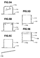
- the plate 112 is then subjected to a deep drawing process as is depicted by Figs. 4B, 4C and 4D to produce a cup-shaped member 114 with a roughly shaped flange 110.
- the deep drawing process is carried out through three drawing steps.
- the cup-shaped member 114 is subjected to a piercing process to provide at a bottom thereof with an opening 114a.
- a peripheral portion of the opening 114a is bent or expanded outward as is indicated by short arrows in Fig.
- the member 114 is subjected to a trimming process to remove an unnecessary part 110b. With this process, the flange 110 becomes shaped circular. Then, as is seen from Fig. 5D, one part 110a of the circular flange 110 is bent at right angles. Then, as is seen from Fig. 5E, the member 114 is subjected to an expansion process to provide the leading end thereof with an annular ridge 108. With this, the pipe member 106 is produced.
- the pipe member 106 is partially fixed or welded to the tank body 102, as is understood from Fig. 1.
- spot welding is applied to three portions P1, P2 and P3 of the unit of the tank body 102 and the pipe member 106, as is seen from Figs. 2 and 3.
- other technique such as caulking, laser beam welding or the like may be used.
- this semi-finished tank 100 Is incompletely mounted to a core structure to provide a so-called semi-finished radiator (not shown), and then the semi-finished radiator is applied with a non-corrosive flux and heated in a furnace. With this, production of the radiator is finished completing brazing of various parts thereof.
- the flange 110 is brazed to the tank body 102 in such a manner as has been described hereinabove.
- the bent shape of the flange 110 of the pipe member 106 facilitates positioning and holding of the pipe member 106 to the tank body 102. That is, the right-angled arcuate part 110a of the flange 110 can be used as a suspending means for suspending the pipe member 106 on the tank body 102, as will be seen from Fig. 1. Since the uppermost end of the circular opening 104 of the side wall 102b is mated with the inner surface of the upper wall 102c of the tank body 102, the height needed by the tank body 102 for connecting with the pipe member 106 is reduced, which brings about a compact construction of the tank 100 and the associated radiator.
- a tank 200 of heat exchanger which is a second embodiment of the present invention.
- tank 200 of this embodiment is similar to that 100 of the above-mentioned first embodiment, only parts and structures which are different from those of the first embodiment 100 will be described in the following.
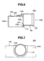
- the circular opening 104 extends to the upper wall 102c of the tank body 102. That is, the opening 104 comprises a generally circular major part formed in the side wall 102b and an arcuate part 104b formed in the upper wall 102c.
- the flange 110 of the pipe member 106 comprises a generally circular major part which is brazed to a peripheral portion of the generally circular opening part of the side wall 102b and a generally rectangular part 110b (see Fig. 8) which is brazed to a peripheral portion of the arcuate opening part 104a of the upper wall 102c.
- Fig. 8 the flange 110 of the pipe member 106 comprises a generally circular major part which is brazed to a peripheral portion of the generally circular opening part of the side wall 102b and a generally rectangular part 110b (see Fig. 8) which is brazed to a peripheral portion of the arcuate opening part 104a of the upper wall 102c.
- the rectangular part 110b of the flange 110 is somewhat raised from the upper wall 102c of the tank body 102.
- the rectangular part 110b is swelled and sloped relative to the upper wall 102c.
- the second embodiment 200 has such an advantaged that the height needed by the tank body 102 for connecting with the pipe member 106 is much reduced, which brings about much compact construction of the tank 200.
- a tank 300 of heat exchanger which is a third embodiment of the present invention.
- the tank 300 of this third embodiment comprises a tank body 102 made of a clad metal, such as a clad aluminum plate or the like.
- the tank body 102 is shaped like a channel member including opposed side walls 102a and 102b and an upper wall 102c.
- the tank body 102 has a lower portion 102d fully opened as shown in Fig. 1.
- An inner surface of the tank body 102 is coated with a corrosion resisting material or self-sacrificing corrosion material, and an outer surface of the tank body 102 is lined with a brazing metal.
- An elongate header plate member 116 is fitted in the lower portion 102d of the tank body 102.
- the header plate member 116 is formed along side edges thereof with respective flanges 116a which are brazed to lower ends of the respective side walls 102a and 102b of the tank body 102.
- An inner surface of the header plate member 116 is coated with a corrosion resisting material or self-sacrificing corrosion material, and an outer surface of the header plate member 116 is lined with a brazing metal.
- the elongate header plate member 116 is formed with a plurality of slits 118 which are arranged at equally spaced intervals along the length thereof.
- the slits 118 receive therein one ends of flat tubes 120 which constitute a core structure of the radiator (not shown).
- end plates 122 are fixed via brazing to longitudinal ends of the tank body 102.
- a pipe member 106 is connected to the tank body 102 in a manner to establish a fluid communication with the tank body 102 through an opening 104 formed in the side wall 102b of the tank body 102.
- a filler neck member 124 Is connected to the upper wall 102c of the tank body 102 in a manner to provide a fluid communication with the tank body 102 through an opening 102e formed in the upper wall 102c.
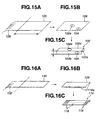
- a rectangular plate 126 is cut out from a coiled plate block 128. Then, as is seen from Fig. 15B, an opening 102e for the filler neck 124 and an opening 104 for the pipe member 106 are formed in the plate 126. Then, as is seen from Fig. 15C, the plate 126 is pressed to have a substantially channel structure. With this, the tank body 102 is produced.
- the header plate member 116 For producing the header plate member 116, as is seen from Fig. 16A, an elongate plate 130 is cut out from a coiled plate block 132. Then, as is seen from Fig. 16B, the plate 130 is pressed to have two flanges 116a along both sides thereof. Then, as is seen from Fig. 16C, the plate 130 is subjected to a punching process to have a plurality of slits 118, and then subjected to a finishing process. With this, the header plate member 116 is produced.
- the pipe member 106 and the filler neck 124 are partially welded to the tank body 102.
- Two header plate members 116 are arranged keeping a given space therebetween.
- a plurality of flat tubes 120 and a plurality of corrugated fins are put between the two header plate members 116.
- opposed ends of each flat tube 120 are snugly inserted in respective slits 118 of the header plate members 116.
- each header plate member 116 there is partially or incompletely connected a corresponding tank body 102 in such a manner as is understood from Fig. 17.
- spot welding is employed, contacting the tapered electrodes 134A and 134B onto the left (or lower) ends of the side walls 102a and 102b.
- each flange 116a of the header plate member 116 and the corresponding end of the side wall 102a or 102b are incompletely fixed.
- the tank body 102 is connected to one terminal of the spot welding device. Since the electric resistance of the tank body 102 is sufficiently high than that of the header plate member 116, such spot welding can be made without using an inner electrode.
- the spot welding is carried out under a condition wherein the pressing force applied by the electrodes 134A and 134B is about 10 to 30 Kgf and the current applied to the electrodes is about 7,000 to 10,000 A.
- the end plates 122 are partially or incompltely fixed to the ends of the tank body 102.
- a so-called semi-finished radiator is provided.
- the semi-finished radiator is applied with a non-corrosive flux and heated in a furnace.
- production of the radiator is finished completing brazing of various parts thereof. That is, with this brazing process, the incompletely fixed portions of the radiator are completely fixed or brazed to each other.
- the tank body 102 in this third embodiment 300 can be produced at a reduced cost as compared with the tank body 102 of the first embodiment 100. In the first embodiment 100, somewhat expensive deep drawing technique is used.
- a tank 400 of heat exchanger which is a fourth embodiment of the present invention.
- tank 400 of this fourth embodiment is similar in construction to the tank 300 of the above-mentioned third embodiment, only portions and parts which are different from those of the third embodiment 300 will be described in detail in the following.
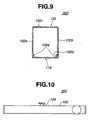
- the tank 400 of this fourth embodiment comprises a tank body 102, a header plate member 116 and two end plates 122 (only one is shown), which are assembled in substantially the same manner as in the case of the third embodiment 300. That is, the header plate member 116 carrying the flat tubes 120 and the corrugated fins 136 is brazed to the open portion 102d of the tank body 102, and the two end plates 122 are brazed to the longitudinal ends of the tank body 102.
- each end plate 122 is formed at an inner surface thereof with two ridges 122a and 122b which extend in parallel. These two ridges 122a and 122b are formed by subjecting the end plate 122 a press working. These ridges 122a and 122b are used for partially or incompletely fixing the end plate 122 to the tank body 102 before effecting the brazing process, as will become apparent as the description proceeds. That is, for carrying out a so-called projection welding, such ridges 122a and 122b are used.
- the ridge 122a extends between ends of the side walls 102a and 102b of the tank body 102, and the other ridge 122b extends between the ends of the flanges 116a of the header plate member 116 as well as between the ends of the side walls 102a and 102b of the tank body 102.
- the end plate 122 is then brazed to the ends of the tank body 102 and the header plate member 116.
- the header plate member 116 carrying the flat tubes 120 (see Fig. 18) and corrugated fins 136 is put into a given position of the tank body 102. Then, each end plate 122 is partially or incompletely fixed to the corresponding ends of the tank body 120 and the header plate member 116 through the projection welding.
- two first flat electrodes 138 are attached to the respective side walls 102a and 102b of the tank body 102, and a second flat electrode 140 is handled to press the end plate 122 by a certain force "F" against the ends of the tank body 102 and the header plate member 116, and a certain voltage is applied between the first and second electrodes 138 and 140.
- each ridge 122a and 122b are welded to the ends of the tank body 102 and the header plate member 116. That is, as is seen from Figs. 21 and 22, longitudinal ends of each ridge 122a or 122b are well welded at positions "W" to the corresponding ends of the tank body 102 and the header plate member 116. With this welding, each end plate 122 is partially or incompletely fixed to the ends having other portions intimately contacting with the same. With this, a so-called semi-finished radiator is provided. Then, the semi-finished radiator is applied with a non-corrosive flux and put into a furnace to be subjected to a brazing process. With this, production of the radiator is finished completing brazing of various parts thereof.
- the incompletely fixed portions of the radiator become completely fixed or brazed to each other. That is, by the heat generated in the furnace, the brazing metal "R" lined on the inner surface of the end plate 122, the header plate member 116 and the tank body 102 is fused for carrying out brazing therebetween. During this, the flat tubes 120 (see Fig. 18), the corrugated fins 136 and the corresponding header plate member 116 achieve the mutual brazing therebetween.
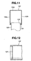
- Figs. 24, 25, 26 and 27 show first, second, third and fourth modifications 400A, 400B, 400C and 400D of the tank 400 of the fourth embodiment.
- the end plate 122A is so oriented that each of ridges 122c and 122d extends between the end of the upper wall 102a of the tank body 102 and the end of the header plate member 116.
- the two ridges 122e and 122f on the end plate 122B are arranged to cross, and the end plate 122B is so oriented that the ridge 122e extends between the ends of the side walls 102a and 102b of the tank body 102 and the other ridge 122f extends between the end of the upper wall 102c of the tank body 102 and the end of the header plate member 116, as shown.
- T-shaped ridge including a first part 122g and a second part 122h is formed on the end plate 122C, and the end plate C 122 is so oriented that the first part 122g extends between the ends of the side walls 102a and 102b of the tank body 102 and the second part 122h extends from the first part 122g to the end of the header plate member 116.
- two flat electrodes 140A and 140B are used, which are handled to press the corresponding end plates 122 by a certain force "F" against the ends of the tank body 102 and the header plate member 116, and a certain voltage is applied between the two flat electrodes 140A and 140B.
- a tank 500 of heat exchanger which is a fifth embodiment of the present invention.
- the flat tubes 120 and the corrugated fins 136 are connected to a tank body 102'.
- an elongate cover plate 116' is employed for covering the open portion of the tank body 102.
- End plates 122 with ridges 122a and 122b are partially or incompletely fixed to ends of the tank body 102' and the cover plate 116' through projection welding and then tightly secured to the same through brazing, like in the case of the above-mentioned fourth embodiment 400.
- one ridge 122a of the end plate 122 extends between the ends of the flanges 116'a of the cover plate 116' as well as between the ends of the side walls 102'a and 102'b of the tank body 102', and the other ridge 122b of the end plate 122 extends between the ends of the side walls 102'a and 102'b of the tank body 102', as shown.
- a tank 600 of heat exchanger which is a sixth embodiment of the present invention.
- the tank 600 of this sixth embodiment comprises a tank body 102 made of a clad metal, such as a clad aluminum plate or the like.
- the tank body 102 is shaped like a channel member including opposed side walls 102a and 102b and an upper wall 102c. As shown in Fig. 32, the tank body 102 has a lower portion 102d fully opened.
- An inner surface of the tank body 102 is coated with a corrosion resisting material of self-sacrificing corrosion material, and an outer surface of the tank body 102 is lined with a brazing metal.
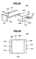
- each pin 142 is a cylindrical hollow member made of a clad metal, such as a clad aluminum plate or the like. An outer surface of the pin 142 is coated with a corrosion resisting material or self-sacrificing corrosion material.
- the pin 142 comprises a cylindrical middle part 142a, a head part 142b and a circular flange part 142c, as shown. The flange part 142c is brazed to the upper wall 102c of the tank body 102.
- a flat plate 144 is subjected to a deep drawing process.
- the deep drawing process is carried out through three drawing steps which are respectively shown in Figs. 33B, 33C and 33D.
- the flange part 142c is trimmed.
- the pin 142 is put on the upper wall 102c of the tank body 102, as is seen from Fig. 31. Then, spot welding is applied to two portions "P1" and "P2" of the flange 142c, as is shown in Fig. 32. With this, the pin 142 is partially or incompletely fixed to the upper wall 102c of the tank body 102. Then, this semi-finished tank 600 is partially or incompletely mounted to a core structure to provide a so-called semi-finished radiator (not shown), and then, the semi-finished radiator is applied with a non-corrosive flux and heated in a furnace. With this, production of the radiator is finished completing brazing of various parts thereof. The flange 142c is brazed to the upper wall 102c of the tank body 102 in such a manner as has been described hereinabove.
- the pin 142 is of a tubular structure, it has only a small heat capacity, which facilitates brazing of the pin 142 to the tank body 102. As is seen from Fig. 35, when a mount rubber 15 is operatively held by the pin 142, the flange 142c of the pin 142 can serve as a seat member.
- Figs. 36, 37 and 38 show first, second and third modifications 600A, 600B and 600C of the tank 600 of the fifth embodiment.
- first modification 600A of Fig. 36 an opening 144 is formed in the head part 142b of the pin 142. Formation of such opening 144 facilitates the deep drawing process and washing of the pin 142.
- second modification 600B of Fig. 37 a projection 146 is formed on the upper wall 102c of the tank body 102 to facilitate positioning of the pin 142 relative to the tank body 102.
- a recess 148 is formed on the upper surface 102c of the tank body 102 to receive therein the flange 142c of the pin 142. With this, positioning and brazing of the pin 142 relative to the tank body 102 are facilitated.
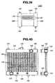
- Fig. 39 shows a radiator 1000 to which two tanks 600 of the fifth embodiment are practically applied.
- the radiator 100 comprises a core structure 1002 and the two tanks 600 which are mounted to opposed ends of the core structure 1002.
- the core structure 1002 comprises a plurality of parallel flat tubes and a plurality of corrugated fins, which extend between the two tanks 600.
- Each tank 600 is provided at its upper and lower ends with pins 142.
Landscapes
- Engineering & Computer Science (AREA)
- Physics & Mathematics (AREA)
- Thermal Sciences (AREA)
- Mechanical Engineering (AREA)
- General Engineering & Computer Science (AREA)
- Details Of Heat-Exchange And Heat-Transfer (AREA)
Applications Claiming Priority (6)
| Application Number | Priority Date | Filing Date | Title |
|---|---|---|---|
| JP10337127A JP2000161895A (ja) | 1998-11-27 | 1998-11-27 | 熱交換器用タンクおよびその製造方法 |
| JP33712798 | 1998-11-27 | ||
| JP10358684A JP2000180086A (ja) | 1998-12-17 | 1998-12-17 | 熱交換器用タンクおよびその製造方法 |
| JP35868498 | 1998-12-17 | ||
| JP30348499A JP2001124488A (ja) | 1999-10-26 | 1999-10-26 | 熱交換器用タンクおよびその製造方法 |
| JP30348499 | 1999-10-26 |
Publications (3)
| Publication Number | Publication Date |
|---|---|
| EP1004841A2 true EP1004841A2 (de) | 2000-05-31 |
| EP1004841A3 EP1004841A3 (de) | 2000-09-13 |
| EP1004841B1 EP1004841B1 (de) | 2003-07-09 |
Family
ID=27338604
Family Applications (1)
| Application Number | Title | Priority Date | Filing Date |
|---|---|---|---|
| EP19990123593 Expired - Lifetime EP1004841B1 (de) | 1998-11-27 | 1999-11-26 | Wasserkasten für Wärmetauscher |
Country Status (2)
| Country | Link |
|---|---|
| EP (1) | EP1004841B1 (de) |
| DE (1) | DE69909408T2 (de) |
Cited By (3)
| Publication number | Priority date | Publication date | Assignee | Title |
|---|---|---|---|---|
| EP1391676A2 (de) | 2002-08-17 | 2004-02-25 | Modine Manufacturing Company | Wärmeaustauscher und Verfahren zur Herstellung |
| DE10343634A1 (de) * | 2003-09-20 | 2005-04-14 | Modine Manufacturing Co., Racine | Wärmeaustauscher für Kraftfahrzeuge |
| CN102284757A (zh) * | 2010-06-18 | 2011-12-21 | 中国北车集团大连机车研究所有限公司 | 板式散热器及其制造方法 |
Citations (1)
| Publication number | Priority date | Publication date | Assignee | Title |
|---|---|---|---|---|
| JPS602195A (ja) | 1984-04-11 | 1985-01-08 | ペルストルプ・ア−ベ− | 多糖類の微生物製造方法 |
Family Cites Families (15)
| Publication number | Priority date | Publication date | Assignee | Title |
|---|---|---|---|---|
| US1572916A (en) * | 1923-08-11 | 1926-02-16 | Carrier Construction Company I | Radiator or the like |
| US2639899A (en) * | 1948-06-18 | 1953-05-26 | Young Radiator Co | Automobile radiator |
| GB1095731A (en) * | 1964-01-13 | 1967-12-20 | Ass Eng Ltd | Improvements in or relating to heat exchanger assemblies |
| BE787265A (fr) * | 1971-08-09 | 1972-12-01 | Chausson Usines Sa | Echangeur de chaleur, notamment pour le chauffage de vehicules |
| JPS57146436A (en) * | 1981-03-06 | 1982-09-09 | Nippon Radiator Co Ltd | Forming method for water conveyance pipe fitting hole of heat exchanger tank |
| GB2098313A (en) * | 1981-05-09 | 1982-11-17 | Imi Radiators | Heat exchanger for automobiles |
| DE4130517B4 (de) * | 1991-09-13 | 2005-12-01 | Behr Gmbh & Co. Kg | Anschlusskasten für einen Wärmetauscher, insbesondere für einen Kältemittelkondensator |
| JP3353475B2 (ja) * | 1994-07-28 | 2002-12-03 | 株式会社デンソー | 熱交換器 |
| JP3368448B2 (ja) * | 1994-12-01 | 2003-01-20 | 株式会社ゼクセルヴァレオクライメートコントロール | 熱交換器のタンクへの出入口パイプ取付構造 |
| JP3624486B2 (ja) * | 1994-12-20 | 2005-03-02 | 株式会社デンソー | 熱交換器およびその製法 |
| JP3420893B2 (ja) * | 1996-07-26 | 2003-06-30 | カルソニックカンセイ株式会社 | 熱交換器用コネクタ装置 |
| KR100565818B1 (ko) * | 1996-08-12 | 2007-04-04 | 칼소닉 칸세이 가부시끼가이샤 | 인테그럴 형 열교환기 |
| JPH10206068A (ja) * | 1997-01-17 | 1998-08-07 | Sanden Corp | 熱交換器用ブラケット |
| JP3912836B2 (ja) * | 1997-02-21 | 2007-05-09 | サンデン株式会社 | 熱交換器 |
| JPH10246591A (ja) * | 1997-03-05 | 1998-09-14 | Sanden Corp | 熱交換器およびその製造方法 |
-
1999
- 1999-11-26 DE DE1999609408 patent/DE69909408T2/de not_active Expired - Fee Related
- 1999-11-26 EP EP19990123593 patent/EP1004841B1/de not_active Expired - Lifetime
Patent Citations (1)
| Publication number | Priority date | Publication date | Assignee | Title |
|---|---|---|---|---|
| JPS602195A (ja) | 1984-04-11 | 1985-01-08 | ペルストルプ・ア−ベ− | 多糖類の微生物製造方法 |
Cited By (4)
| Publication number | Priority date | Publication date | Assignee | Title |
|---|---|---|---|---|
| EP1391676A2 (de) | 2002-08-17 | 2004-02-25 | Modine Manufacturing Company | Wärmeaustauscher und Verfahren zur Herstellung |
| US6971445B2 (en) | 2002-08-17 | 2005-12-06 | Modine Manufacturing Company | Heat exchanger and method of production |
| DE10343634A1 (de) * | 2003-09-20 | 2005-04-14 | Modine Manufacturing Co., Racine | Wärmeaustauscher für Kraftfahrzeuge |
| CN102284757A (zh) * | 2010-06-18 | 2011-12-21 | 中国北车集团大连机车研究所有限公司 | 板式散热器及其制造方法 |
Also Published As
| Publication number | Publication date |
|---|---|
| EP1004841A3 (de) | 2000-09-13 |
| EP1004841B1 (de) | 2003-07-09 |
| DE69909408D1 (de) | 2003-08-14 |
| DE69909408T2 (de) | 2004-05-19 |
Similar Documents
| Publication | Publication Date | Title |
|---|---|---|
| US5036914A (en) | Vehicle-loaded parallel flow type heat exchanger | |
| JPH08226786A (ja) | 熱交換器およびその製法 | |
| US5214847A (en) | Method for manufacturing a heat exchanger | |
| JP4161446B2 (ja) | 熱交換器 | |
| JPH05318098A (ja) | 熱交換器 | |
| WO2001049443A1 (fr) | Echangeur thermique | |
| JP2002286396A (ja) | 熱交換器 | |
| US6513585B2 (en) | Header-less vehicle radiator | |
| EP0840081B1 (de) | Wärmetauscher und Verfahren zu dessen Herstellung | |
| JP2008256242A (ja) | 熱交換器用チューブ | |
| JPH09126685A (ja) | 熱交換器 | |
| US6450253B1 (en) | Tank of heat exchanger | |
| EP1643201B1 (de) | Wärmeaustauschvorrichtung für KFZ | |
| EP1004841B1 (de) | Wasserkasten für Wärmetauscher | |
| US20010037878A1 (en) | Header-less vehicle radiator | |
| US5868196A (en) | Mounting bracket for heat exchanger | |
| US7552756B2 (en) | Brazed aluminum radiator with PTO section and method of making the same | |
| JPH0749264Y2 (ja) | 熱交換器 | |
| EP1561524A1 (de) | Öffnungsausdehnvorrichtung fur Wärmetauschrohr | |
| JPH11223477A (ja) | 自動車用複合型熱交換器およびその製造方法 | |
| JP3800130B2 (ja) | 熱交換器 | |
| JP4013298B2 (ja) | 熱交換器およびその製造方法 | |
| KR100531017B1 (ko) | 열교환 유동 플레이트의 메니폴드 접합용 브레이징재 및열교환 유동 플레이트의 메니폴드 접합방법 | |
| JP4866571B2 (ja) | 熱交換器 | |
| EP1433547B1 (de) | Wärmetauscher und verfahren zur herstellung des wärmetauschers |
Legal Events
| Date | Code | Title | Description |
|---|---|---|---|
| PUAI | Public reference made under article 153(3) epc to a published international application that has entered the european phase |
Free format text: ORIGINAL CODE: 0009012 |
|
| 17P | Request for examination filed |
Effective date: 19991126 |
|
| AK | Designated contracting states |
Kind code of ref document: A2 Designated state(s): DE FR GB |
|
| AX | Request for extension of the european patent |
Free format text: AL;LT;LV;MK;RO;SI |
|
| PUAL | Search report despatched |
Free format text: ORIGINAL CODE: 0009013 |
|
| AK | Designated contracting states |
Kind code of ref document: A3 Designated state(s): AT BE CH CY DE DK ES FI FR GB GR IE IT LI LU MC NL PT SE |
|
| AX | Request for extension of the european patent |
Free format text: AL;LT;LV;MK;RO;SI |
|
| RAP1 | Party data changed (applicant data changed or rights of an application transferred) |
Owner name: CALSONIC KANSEI CORPORATION |
|
| AKX | Designation fees paid |
Free format text: DE FR GB |
|
| 17Q | First examination report despatched |
Effective date: 20020529 |
|
| GRAH | Despatch of communication of intention to grant a patent |
Free format text: ORIGINAL CODE: EPIDOS IGRA |
|
| GRAH | Despatch of communication of intention to grant a patent |
Free format text: ORIGINAL CODE: EPIDOS IGRA |
|
| GRAA | (expected) grant |
Free format text: ORIGINAL CODE: 0009210 |
|
| AK | Designated contracting states |
Designated state(s): DE FR GB |
|
| REG | Reference to a national code |
Ref country code: GB Ref legal event code: FG4D |
|
| REF | Corresponds to: |
Ref document number: 69909408 Country of ref document: DE Date of ref document: 20030814 Kind code of ref document: P |
|
| PGFP | Annual fee paid to national office [announced via postgrant information from national office to epo] |
Ref country code: GB Payment date: 20031027 Year of fee payment: 5 |
|
| PGFP | Annual fee paid to national office [announced via postgrant information from national office to epo] |
Ref country code: FR Payment date: 20031120 Year of fee payment: 5 |
|
| PGFP | Annual fee paid to national office [announced via postgrant information from national office to epo] |
Ref country code: DE Payment date: 20031223 Year of fee payment: 5 |
|
| PLBE | No opposition filed within time limit |
Free format text: ORIGINAL CODE: 0009261 |
|
| STAA | Information on the status of an ep patent application or granted ep patent |
Free format text: STATUS: NO OPPOSITION FILED WITHIN TIME LIMIT |
|
| ET | Fr: translation filed | ||
| 26N | No opposition filed |
Effective date: 20040414 |
|
| PG25 | Lapsed in a contracting state [announced via postgrant information from national office to epo] |
Ref country code: GB Free format text: LAPSE BECAUSE OF NON-PAYMENT OF DUE FEES Effective date: 20041126 |
|
| PG25 | Lapsed in a contracting state [announced via postgrant information from national office to epo] |
Ref country code: DE Free format text: LAPSE BECAUSE OF NON-PAYMENT OF DUE FEES Effective date: 20050601 |
|
| GBPC | Gb: european patent ceased through non-payment of renewal fee |
Effective date: 20041126 |
|
| PG25 | Lapsed in a contracting state [announced via postgrant information from national office to epo] |
Ref country code: FR Free format text: LAPSE BECAUSE OF NON-PAYMENT OF DUE FEES Effective date: 20050729 |
|
| REG | Reference to a national code |
Ref country code: FR Ref legal event code: ST |