EP1004697B1 - Vorrichtung und Verfahren zum Umwickeln, teilweisen Färben und Auswickeln von Garnen - Google Patents
Vorrichtung und Verfahren zum Umwickeln, teilweisen Färben und Auswickeln von Garnen Download PDFInfo
- Publication number
- EP1004697B1 EP1004697B1 EP99309295A EP99309295A EP1004697B1 EP 1004697 B1 EP1004697 B1 EP 1004697B1 EP 99309295 A EP99309295 A EP 99309295A EP 99309295 A EP99309295 A EP 99309295A EP 1004697 B1 EP1004697 B1 EP 1004697B1
- Authority
- EP
- European Patent Office
- Prior art keywords
- yarn
- yarns
- wrapper
- dyeing
- feed yarns
- Prior art date
- Legal status (The legal status is an assumption and is not a legal conclusion. Google has not performed a legal analysis and makes no representation as to the accuracy of the status listed.)
- Expired - Lifetime
Links
- 238000009977 space dyeing Methods 0.000 title claims description 59
- 238000000034 method Methods 0.000 title claims description 50
- 239000002131 composite material Substances 0.000 claims description 41
- 238000004043 dyeing Methods 0.000 claims description 11
- 238000004804 winding Methods 0.000 claims description 11
- 238000010924 continuous production Methods 0.000 claims description 6
- 238000000926 separation method Methods 0.000 claims description 4
- 238000009970 yarn dyeing Methods 0.000 claims description 4
- 230000003252 repetitive effect Effects 0.000 claims description 2
- 238000010025 steaming Methods 0.000 claims description 2
- 238000010586 diagram Methods 0.000 description 5
- 239000000047 product Substances 0.000 description 5
- OKTJSMMVPCPJKN-UHFFFAOYSA-N Carbon Chemical compound [C] OKTJSMMVPCPJKN-UHFFFAOYSA-N 0.000 description 3
- 239000004784 Superba Substances 0.000 description 3
- 241000324401 Superba Species 0.000 description 3
- 238000001035 drying Methods 0.000 description 3
- 239000004744 fabric Substances 0.000 description 3
- 230000015572 biosynthetic process Effects 0.000 description 2
- 239000007795 chemical reaction product Substances 0.000 description 2
- 230000007547 defect Effects 0.000 description 2
- 239000000463 material Substances 0.000 description 2
- 229920000728 polyester Polymers 0.000 description 2
- 238000005406 washing Methods 0.000 description 2
- 239000004677 Nylon Substances 0.000 description 1
- 239000003086 colorant Substances 0.000 description 1
- 239000000470 constituent Substances 0.000 description 1
- 239000000835 fiber Substances 0.000 description 1
- 239000012530 fluid Substances 0.000 description 1
- 238000002347 injection Methods 0.000 description 1
- 239000007924 injection Substances 0.000 description 1
- 229920001778 nylon Polymers 0.000 description 1
- XLYOFNOQVPJJNP-UHFFFAOYSA-N water Substances O XLYOFNOQVPJJNP-UHFFFAOYSA-N 0.000 description 1
Images


Classifications
-
- D—TEXTILES; PAPER
- D02—YARNS; MECHANICAL FINISHING OF YARNS OR ROPES; WARPING OR BEAMING
- D02G—CRIMPING OR CURLING FIBRES, FILAMENTS, THREADS, OR YARNS; YARNS OR THREADS
- D02G3/00—Yarns or threads, e.g. fancy yarns; Processes or apparatus for the production thereof, not otherwise provided for
- D02G3/22—Yarns or threads characterised by constructional features, e.g. blending, filament/fibre
- D02G3/38—Threads in which fibres, filaments, or yarns are wound with other yarns or filaments, e.g. wrap yarns, i.e. strands of filaments or staple fibres are wrapped by a helically wound binder yarn
- D02G3/385—Threads in which fibres, filaments, or yarns are wound with other yarns or filaments, e.g. wrap yarns, i.e. strands of filaments or staple fibres are wrapped by a helically wound binder yarn using hollow spindles, e.g. making coverspun yarns
-
- D—TEXTILES; PAPER
- D06—TREATMENT OF TEXTILES OR THE LIKE; LAUNDERING; FLEXIBLE MATERIALS NOT OTHERWISE PROVIDED FOR
- D06B—TREATING TEXTILE MATERIALS USING LIQUIDS, GASES OR VAPOURS
- D06B11/00—Treatment of selected parts of textile materials, e.g. partial dyeing
- D06B11/002—Treatment of selected parts of textile materials, e.g. partial dyeing of moving yarns
- D06B11/0036—Treatment of selected parts of textile materials, e.g. partial dyeing of moving yarns specially disposed for a local treatment
Definitions
- This invention relates to a process for space-dyeing fine denier yarns.
- the process involves wrapping fine denier yarns with a wrapper yarn before space dyeing the composite bundle of yarns, and subsequently unwrapping the fine denier yarns for further processing as individual yarns.
- the invention also relates to an apparatus for wrapping of fine denier yarns for space dyeing and subsequently unwrapping the fine denier yarns for further processing, an intermediate yarn product formed of bundled fine denier yarns suitable for space-dyeing in a continuous process, and an end product, fine denier yarn which results from the process carried out on the intermediate yarn product.
- Continuous dye lines are typically used for space-dyed carpet yarns.
- Carpets are typically tufted from yarns in the 1000-3000 denier range.
- the denier range for this type of space-dyed yarns is 150 to 500 denier.
- Some automotive upholstery fabric is spaced-dyed using a proprietary needle injection dyc process. Quality problems with this process are significant and typically result in dye spot length differences between the outside of the packages and the inside, or core, of the package. This can cause significant pattern repeat defects in the finished fabric.
- Some fabric manufactures typically back-wind 1 package, and then parallel wind the back-wound yarn with another space dye yarn just to hide the pattern repeat defects. This can require that a significant percentage of the yarn be scrapped, since a good portion of the core yarn on each package is not dyed the same shade as the rest of the package.
- Applicant's applicator, dye line and winder are set up to run at a maximum speed of 500 YPM with 48 running yarn ends. With these speeds, running 150 denier yarn would not be economically practical because of lack of productivity.
- DE 4218550 discloses a method for the treatment of yarn material comprising the formation of a yarn bundle. However, the bundle is then piled in layers in a vessel such that treatment fluid and/or dye flows at and/or through the piled material.
- DE 2334482 discloses a method for imprinting a mat of yarns which comprises bundling a number of separate yarns coming from a feed station into a bunch. However, the bunch is then laid on a conveyor belt in the form of a mat, flat sheet, blanket, or the like before at least one dye is applied to the mat. The imprinted mat is conveyed into a unit for drying and fixing the dye and then the dried and imprinted yarns are taken up again.
- Yarn wrapping per se is a conventional process.
- known prior art uses of this process generally involve wrapping a yarn to achieve a wrapped end product.
- the prior art does not disclose the formation of an intermediate yarn product which is processed by space-dyeing, whereupon the intermediate yarn product is disassembled into its constituent, end use parts with the wrapper yarn being sacrificed.
- a method for space-dyeing yarns comprising the steps of wrapping a plurality of feed yarns with a sacrificial wrapper yarn to form a composite yarn bundle, space-dyeing the composite yarn bundle, removing the wrapper yarn from around the feed yarns, separating the feed yarns into individual yarns for further processing.
- the method includes the step of winding the composite yarn bundle onto a yarn package after the space-dyeing step.
- the step of removing the wrapper yarn from around the feed yarns comprises the step of unwrapping the wrapper yarn from around the feed yarns.
- the step of removing the wrapper yarn from around the feed yarns comprises the step of cutting the wrapper yarn away from the feed yarns.
- a further embodiment of the method according to the invention comprises the steps of spreading the composite yarn bundle to expose the wrapper yarn in advance of the feed yarns to a blade and cutting the wrapper yarn away from the feed yarns at a point in advance of the feed yarns.
- the method includes the step of aspirating the cut wrapper yarn to remove it from the feed yarns.
- the method includes the step of winding the separated feed yarns onto individual yarn packages.
- the process steps arc carried out in a continuous process on a single apparatus having a series of process stations.
- the process steps are carried out in a series of discrete steps on separate machines.
- the steps of coiling, steaming and dyeing the composite yarn bundle take place after space-dyeing and before separating the wrapper yarn from the feed yarns.
- each of the plurality of feed yarns comprises a synthetic yarn having a denier of 500 or less.
- each of the plurality of feed yarns comprises a synthetic yarn having a denier of 150 or less.
- the step of wrapping a plurality of feed yarns with a sacrificial wrapper yarn comprises the step of wrapping the feed yarns with between 2 and 10 wraps of the wrapper yarn per 25.4 mm (inch).
- the wrapper yarn comprises a yarn having a denier of between 20 and 150 denier.
- the step of space-dyeing the composite yarn bundle comprises the step of passing the composite yarn bundle through a plurality of yarn-dyeing stations, each of said yarn dyeing stations including a rotatable pattern member permitting a dye to be applied to the yarn in seriatim only when disposed in a selected angular disposition relative to said yarn bundle, each pattern member being associated with a different color dye, the speed of each member controlling the angle through which each of the members rotates during repetitive time periods so that the disposition required to permit dyeing of yarn by each color may be obtained at selected times.
- the method includes the step of coordinating the location along the yarn bundle at which each member permits dye to be applied, whereby each different color dye may be applied along different amounts of the yarn bundle and at selected locations.
- the step of space-dyeing the composite yarn bundle comprises the steps of feeding said yarn bundle in one direction through said stations, locating a dye applying means at each station for applying dye of a selected color onto said yarn bundle, locating a rotatable pattern member at each station for selectively permitting and preventing dye to be applied to said yarn bundle by the respective dye applying means, and controllably rotating each pattern member independently of the other pattern members in accordance with a pattern to selected positions to permit dye to be applied to said yarn at selected times and to prevent dye to be applied to the yarn at other times.
- An apparatus for space-dyeing yarns in accordance with the invention comprises a yarn-wrapping apparatus for wrapping a plurality of feed yarns with a sacrificial wrapper yarn to form a composite yarn bundle, a space-dyeing apparatus for space-dyeing the composite yarn bundle, a wrapper yarn removal apparatus for removing the wrapper yarn from around the feed yarns, and a feed yarn separating apparatus for separating the feed yarns into individual yarns for further processing.
- the invention includes a winder for winding the composite yarn bundle onto a yarn package after the space-dyeing step.
- the apparatus for removing the wrapper yarn from around the feed yarns comprises an apparatus for unwrapping the wrapper yarn from around the feed yarns.
- the apparatus for removing the wrapper yarn from around the feed yarns comprises a cutter blade for cutting the wrapper yarn away from the feed yarns.
- the apparatus for removing the wrapper yarn from around the feed yarns includes a yarn bundle spreader for spreading the composite yarn bundle to expose the wrapper yarn in advance of the feed yarns to a blade and wherein the cutter blade cuts the wrapper yarn away from the fced yarns at a point in advance of the feed yarns.
- Another embodiment of the apparatus for space-dyeing yarns comprises yarn wrapping means for wrapping a plurality of feed yarns with a sacrificial wrapper yarn to form a composite yarn bundle, space-dyeing means for space-dyeing the compositc yarn bundle, wrapper yarn removal means for removing the wrapper yarn from around the feed yarns; and separator means for separating the feed yarns into individual yarns for further processing.
- winding means are provided for winding the composite yarn bundle onto a yarn package after the space-dyeing step.
- wrapper removal means are provided for removing the wrapper yarn from around the feed yarns comprises the step of unwrapping the wrapper yarn from around the feed yarns.
- the wrapper yarn removal means comprises a cutter blade for cutting the wrapper yarn away from the feed yarns.
- a composite yarn bundle for permitting space-dyeing of fine denier yarns comprises a plurality of fine denier feed yarns integrated together in parallel configuration to form an integrated core, and a sacrificial wrapper yarn wrapped around the core to form a composite yarn bundle wherein the feed yarns are maintained in integrated condition during space-dyeing, said sacrificial wrapper adapted to be removed from around the feed yarns after space-dyeing to permit separation of the core into individual feed yarns for subsequent processing.
- each of said feed yarns is 500 denier or less.
- each of said feed yarns is 150 denier or less.
- each of said feed yarns is 50 denier or less.
- the wrapper yarn is 50 denier or less.
- the wrapper yarn is wrapped onto the core with between 2 and 10 wraps per 25.4 mm (inch).
- a space-dyed, fine denier yarn according to the invention comprises a feed yarn of no more than 500 denier, a plurality of colors of dye applied to the feed yarn by moving the feed yarn past a dye-applying apparatus while integrated together with a plurality of like feed yarns by means of at least one sacrificial wrapper yarn wrapped around said feed yarns to maintain the feed yarns in their integrated condition, said wrapper yarn being removed from the feed yarn after space-dyeing.
- fine denier feed yarns refers to yarns having a denier from between 50 to 500 denier, and may be formed from any synthetic staple or continuous filament fiber, such as polyester or nylon.
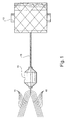
- 10 ends of 150 denier feed yarn 10 form a core and are wrapped with a 40 denier sacrificial wrapper yarn 11 to form an intermediate yarn product in the form of a 1500 denier composite yarn bundle 12 which can be conventionally spaced-dyed.
- the yarn bundle 12 is then wound onto a conventional yarn package 13.
- the number of wraps should be as low as possible and only just sufficient to keep the fine denier feed yarns bundled together for dyeing. Wraps in the range of from 2 to 10 wraps per 25.4 mm (inch) should be suitable. This results in this size yarn is very similar to the size of carpet yarn, which is routinely space-dyed with excellent results.
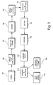
- Fi gure 2 the proper number of packages 13 of composite yarn bundles 12, for example, 36 to 48, arc put in the creel 20 of the dyeing machine 30 and space-dyed.
- the efficiency and robustness of the dyeing process may even be better than with carpet yarn, as the composite yarn bundle 12 is quite strong.
- the feed yarns 10 can be retied as bundles, as the wrapper yarn 11 would not be lost.
- the space-dyeing process includes applying post-dye steam at a steamer 40, coiling the ccc at a coiler 50, fixing the dye with steam at a steamer 60, washing and extracting water at a washer/extractor 70 drying the ccc in a dryer 80, and then winding the ccc onto yarn packages in a conventional winder 90, such as a Belmont AD-30 or AD-35, or a Superba BLA or B400.
- a conventional winder 90 such as a Belmont AD-30 or AD-35, or a Superba BLA or B400.
- the space-dyeing process can be carried out by any conventional means.
- Applicant's space-dyeing process includes a series of dye stations, each of which has a dye applicator roll and a rotatable pattern roll having deflecting rods which deflect yarn into engagement with the periphery of the respective dye applicator roll as they rotate.
- Each pattern roll is rotatably driven by a servo motor and selectively rotated to position the deflecting rods for permitting dyeing to occur at the respective station and to rotate the roll and thus the rods to angular positions where the yarn is not deflected.
- a programmable controller directs the respective motors to the selected angular positions at precise times to start and stop the application of dye to the yarn.
- the controller is informed of the speed of the yarn movement so that rotation of each pattern roll is in timed relationship with the movement of the yarn. See, Patent No. 5,594,968. An earlier embodiment of this space-dyeing arrangement is disclosed in Patent No. 5,339,658.
- space-dyeing machines which may be used include a space-dyeing machine manufactured by Superba, S.A. which includes a series of dye stations, each of which has a dye applicator nozzle and a rotatable pattern disk having openings which permits and prevents dye from the nozzle to reach the moving yarn as the disks rotate.
- Each pattern disk is rotatably driven by a servo motor and selectively rotated to position the disk for permitting dyeing to occur at the respective station and to rotate the disk to angular positions where the yarn is not dyed.
- a programmable controller directs the respective motors to the selected angular positions at precise times to start and stop the application of dye to the yarn.
- the controller is informed of the speed of the yarn movement so that rotation of each pattern disk is in timed relationship with the movement of the yarn.
- Other Superba space-dyeing machines which may be suitable include those disclosed in United States Patent Nos. 5,557,953 and 5,491,858.
- the space-dyeing takes place under the overall control of a computer based upon settings entered into the computer and transferred to the controller.
- the yarn speed may be continuously monitored and fed to the controller for adjusting the action of the servo motors in a corresponding fashion, or the yarn speed may be continuously monitored and maintained at a precise speed by means of a feedback loop between the nominal yarn speed value selected at the computer and the monitored speed.
- the dyed, wound packages are removed from the winder 90 and placed on a conventional unwind stand 100, and unwrapped by removing the wrapper yarn 11 at an unwrapping apparatus 110 and separating the now-liberated feed yarns 10 into individual yarns for winding onto a standard package at a winder 120. See Figures 2 and 3.
- the sacrificial wrapper yarn 11 is disposed of by, for example, an aspirator jet 120 which conveys away the wrapper yarn 11 at a discard station 130.
- the wrapper yarn 11 may be removed at the unwrapping apparatus 110 in a number of ways.
- a knife blade 112 may be used to cut the wrapper yarn 11 away from the yarn bundle 12. This is accomplished by spreading the bundle 12 to form a v-shaped gap in the feed yarns 10 and exposing the wrapper yarn 11 to the blade 112.
- the blade 112 cuts the wrapper yarn 11 as the yarn bundle 12 is continuously spread immediately in advance of the blade 112.
- the space-dyed feed yarns 10 are separated and carried away from the cutting area while separated by a series of laterally-spaced separation pins at unwrapping and separating apparatus 110 for further processing.
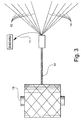
- the overall steps of the method can be carried out continuously.
- the yarns 10 are brought from a creel 200 and pass through separation pins 210 and are brought together and wrapped with a fine denier wrapper yarn 11 to form a composite yarn bundle 12, as described above.
- a parallel array of yarn wrapping devices 220 which may be false-twist devices, form the composite yarn bundles 12 in a parallel array and deliver them to a space-dyeing apparatus 230.
- the warp of ccc pass through a post-dye steamer 240, coiler 250, steamer 260, washer, extractor 270 and dryer 280.
- the ccc pass through a pair of hold-back rolls 290 and then a series of laterally-spaced, disk-shaped rotating blades 300.
- the blades 300 are used to sever the wrapper yarns 11 of the respective yarn bundles 12. As described above, this is accomplished by spreading the bundle 12 to form a gap in the feed yarns 10, thus exposing the wrapper yarn 11 to the rotating blade 300.
- Another set of separator pins 310 keeps the ccc separated during the cutting of the wrapper yarn 11.
- Tensioning rolls 320 maintain tension on the ccc in cooperation with the hold-back rolls 290.
- the unwrapped feed yarns 10 are delivered to a winder for winding in a conventional manner, and the wrapper yarn 11 is discarded.
Landscapes
- Engineering & Computer Science (AREA)
- Textile Engineering (AREA)
- Chemical & Material Sciences (AREA)
- Materials Engineering (AREA)
- Mechanical Engineering (AREA)
- Treatment Of Fiber Materials (AREA)
- Coloring (AREA)
Claims (28)
- Verfahren zum teilweisen Färben (space-dyeing) von Garnen, das die folgenden Schritte aufweist:(a) Umwickeln mehrerer zugeführter Garne (10) mit einem Opfer-Umwickelgarn (11) zur Bildung eines zusammengesetzten Garnbündels (12);(b) teilweises Färben des zusammengesetzten Garnbündels (12);(c) Entfernen des Umwickelgarnes (11) von den zugeführten Garnen (10); und(d) Trennen der zugeführten Garne (10) in einzelne Garne zur weiteren verarbeitung.
- Verfahren nach Anspruch 1, das den Schritt eines Aufwickelns des zusammengesetzten Garnbündels (12) auf ein Garnpaket (13) nach dem Schritt des teilweisen Färbens aufweist.
- Verfahren nach Anspruch 1, bei dem der Schritt des Entfernens des Umwickelgarnes (11) von den zugeführten Garnen (10) den Schritt des Abwickelns des Umwickelgarnes (11) von den zugeführten Garnen (10) aufweist.
- Verfahren nach Anspruch 1, bei dem der Schritt des Entfernens des Umwickelgarnes (11) von den zugeführten Garnen (10) den Schritt des Abschneidens des Umwickelgarnes (11) weg von den zugeführten Garnen (10) aufweist.
- Verfahren nach Anspruch 4, das die folgenden Schritte aufweist:(a) Spreizen des zusammengesetzten Garnbündels (12), um das Umwickelgarn (11) vor den zugeführten Garnen (10) für eine Klinge (112) freizulegen; und(b) Abschneiden des Umwickelgarnes (11) weg von den zugeführten Garnen (10) an einer Stelle vor den zugeführten Garnen (10).
- Verfahren nach Anspruch 4 oder 5, das den Schritt des Ansaugens des abgeschnittenen Umwickelgarnes (11) umfasst, um es von den zugeführten Garnen (10) zu entfernen.
- Verfahren nach Anspruch 6, das den Schritt eines Aufwickelns der getrennten zugeführten Garne (10) auf einzelne Garnpakete (13) umfasst.
- Verfahren nach Anspruch 1, bei dem die Verfahrensschritte in einem kontinuierlichen Prozess mit einer einzigen Vorrichtung mit mehreren verarbeitungsstationen durchgeführt werden.
- verfahren nach Anspruch 1, bei dem die Verfahrensschritte in einer Folge diskreter Schritte mit getrennten Vorrichtungen durchgeführt werden.
- Verfahren nach Anspruch 1, das die Schritte des Aufwickelns, Eindämpfens und Färbens des zusammengesetzten Garnbündels (12) nach dem teilweisen Färben und vor dem Trennen des Umwickelgarnes (11) von den zugeführten Garnen (10) umfasst.
- Verfahren nach Anspruch 1, bei dem jedes der mehreren zugeführten Garne (10) ein synthetisches Garn mit einem Denier von 500 oder weniger aufweist.
- Verfahren nach Anspruch 1, be dem jedes der mehreren zugeführten Garne (10) ein synthetisches Garn mit einem Denier von 150 oder weniger aufweist.
- Verfahren nach Anspruch 1, bei dem der Schritt des Umwickelns mehrerer zugeführter Garne (10) mit einem Opfer-Umwickelgarn (11) den Schritt des Umwickelns der zugeführten Garne (10) mit zwischen 2 und 10 Windungen des Umwickelgarnes (11) pro 25,4 mm (pro Zoll) aufweist.
- Verfahren nach Anspruch 11, 12 oder 13, bei dem das Umwickelgarn (11) ein Garn mit einem Denier von zwischen 20 und 150 Denier aufweist.
- Verfahren nach Anspruch 1, bei dem der Schritt des teilweisen Färbens des zusammengesetzten Garnbündels (12) den Schritt des Durchlaufens des zusammengesetzten Garnbündels (12) durch mehrere Garnfärbstationen (30) umfasst, wobei jede der genannten Garnfärbstationen (30) ein drehbares Muster-Element aufweist, das ein aufeinanderfolgendes Auftragen eines Farbstoffs auf das Garn nur dann ermöglicht, wenn es sich in einer ausgewählten Winkellage in Bezug auf das genannte Garnbündel (12) befindet, wobei jedem Muster-Element ein anderer Farbstoff zugeordnet ist und wobei die Geschwindigkeit jedes Elementes den Winkel, um den sich jedes der Elemente während sich wiederholender Zeitperioden dreht, derart bestimmt, dass die Lage, die für das Färben des Garnes mit jeder Farbe erforderlich ist, zu ausgewählten Zeitpunkten erreicht werden kann.
- Verfahren nach Anspruch 15, das den Schritt des Koordinierens der Stelle entlang des Garnbündels (12) umfasst, an der jedes Element ein Auftragen eines Farbstoffs ermöglicht, wodurch die jeweiligen Farbstoffe auf unterschiedliche Längen des Garnbündels (12) und an ausgewählten Stellen aufgetragen werden können.
- Verfahren nach Anspruch 1, bei dem der Schritt des teilweisen Färbens des zusammengesetzten Garnbündels (12) die folgenden Schritte aufweist:(a) Führen des genannten Garnbündels (12) in einer Richtung durch Stationen (30);(b) Anordnen eines Farbauftragmittels an jeder Station (30) zum Auftragen eines Farbstoffs der ausgewählten Farbe auf das genannte Garnbündel (12); und(c) Anordnen eines drehbaren Muster-Elementes an jeder Station (30) zum wahlweisen Ermöglichen und Verhindern des Auftragens des Farbstoffs auf das genannte Garnbündel (12) durch die jeweiligen Farbauftragmittel; und - nach Vorgabe eines Musters - gesteuertes Drehen jedes Muster-Elementes unabhängig von den anderen Muster-Elementen in ausgegewählte Positionen, um das Auftragen des Farbstoffs auf das genannte Garn zu ausgewählten Zeitpunkten zu ermöglichen und das Auftragen des Farbstoffs auf das genannte Garn zu anderen Zeitpunkten zu verhindern.
- Vorrichtung zum teilweisen Färben von Garnen, die aufweist:(a) eine Garnumwickelvorrichtung (220) zum Umwickeln mehrerer zugeführter Garne (10) mit einem Opfer-Umwickelgarn (11) zur Bildung eines zusammengesetzten Garnbündels;(b) eine "Space-dyeing"-Vorrichtung (230) zum teilweisen Färben des zusammengesetzten Garnbündels;(c) eine Umwickelgarn-Entfernungsvorrichtung zum Entfernen des Umwickelgarnes (11) von den zugeführten Garnen (10); und(d) eine Trennvorrichtung (310) für die zugeführten Garne zum Trennen der zugeführten Garne (10) in einzelne Garne zur weiteren Verarbeitung.
- Vorrichtung zum teilweisen Färben von Garnen nach Anspruch 18, die eine Aufwickelvorrichtung zum Aufwickeln des zusammengesetzten Garnbündels (12) auf ein Garnpaket nach dem Schritt des teilweisen Färbens aufweist.
- Vorrichtung zum teilweisen Färben von Garnen nach Anspruch 18, bei der die Vorrichtung zum Entfernen des Umwickelgarnes (11) von den zugeführten Garnen (10) eine Vorrichtung zum Abwickeln des Umwickelgarnes (11) von den zugeführten Garnen (10) aufweist.
- Vorrichtung zum teilweisen Färben von Garnen nach Anspruch 18, bei der die Vorrichtung zum Entfernen des Umwickelgarnes (11) von den zugeführten Garnen (10) eine Abschneideklinge (300) zum Abschneiden des Umwickelgarnes (11) weg von den zugeführten Garnen (10) aufweist.
- Vorrichtung zum teilweisen Färben von Garnen nach Anspruch 21, bei der die Vorrichtung zum Entfernen des Umwickelgarnes (11) von den zugeführten Garnen (10) eine Garnbündelspreizvorrichtung zum Spreizen des zusammengesetzten Garnbündels (12) aufweist, um das Umwickelgarn (11) vor den zugeführten Garnen (10) für eine Klinge (300) freizulegen, wobei die Abschneideklinge (300) das Umwickelgarn (11) weg von den zugeführten Garnen (10) an einer Stelle vor den zugeführten Garnen (10) abschneidet.
- Zusammengesetztes Garnbündel (12) zum Ermöglichen des teilweisen Färbens von Feindeniergarnen, das aufweist:(a) mehrere zugeführte Feindeniergarne (10), die parallel zusammengesetzt sind, um einen integrierten Kern zu bilden, und(b) ein Opfer-Umwickelgarn (11), das um den Kern gewickelt ist, um ein zusammengesetztes Garnbündel (12) zu bilden, wobei die zugeführten Garne (10) während des teilweisen Färbens im zusammengesetzten Zustand gehalten werden, und wobei das Opfer-Umwickelgarn (11) nach dem teilweisen Färben von den zugeführten Garnen (10) entfernt wird, um eine Trennung des Kerns in einzelne zugeführte Garne (10) zur weiteren Verarbeitung zu ermöglichen.
- Zusammengesetztes Garnbündel (12) nach Anspruch 23, bei dem jedes der genannten zugeführten Garne (10) ein Denier von 500 oder weniger-aufweist.
- Zusammengesetztes Garnbündel (12) nach Anspruch 23, bei dem jedes der genannten zugeführte Garne (10) ein Denier von 150 und weniger aufweist.
- Zusammengesetztes Garnbündel (12) nach Anspruch 23, bei dem jedes der genannten zugeführten Garne (10) ein Denier von 50 oder weniger aufweist.
- Zusammengesetztes Garnbündel (12) nach Anspruch 23, bei dem das Umwickelgarn (11) ein Denier von 50 oder weniger aufweist.
- Zusammengesetztes Garnbündel (12) nach Anspruch 23, bei dem das Umwickelgarn (11) auf den Kern mit zwischen 2 und 10 Windungen pro 25,4 mm (pro Zoll) aufgewickelt ist.
Applications Claiming Priority (2)
| Application Number | Priority Date | Filing Date | Title |
|---|---|---|---|
| US10960598P | 1998-11-23 | 1998-11-23 | |
| US109605P | 1998-11-23 |
Publications (3)
| Publication Number | Publication Date |
|---|---|
| EP1004697A2 EP1004697A2 (de) | 2000-05-31 |
| EP1004697A3 EP1004697A3 (de) | 2000-10-25 |
| EP1004697B1 true EP1004697B1 (de) | 2004-06-23 |
Family
ID=22328573
Family Applications (1)
| Application Number | Title | Priority Date | Filing Date |
|---|---|---|---|
| EP99309295A Expired - Lifetime EP1004697B1 (de) | 1998-11-23 | 1999-11-22 | Vorrichtung und Verfahren zum Umwickeln, teilweisen Färben und Auswickeln von Garnen |
Country Status (3)
| Country | Link |
|---|---|
| US (1) | US6494922B1 (de) |
| EP (1) | EP1004697B1 (de) |
| DE (1) | DE69918247T2 (de) |
Families Citing this family (5)
| Publication number | Priority date | Publication date | Assignee | Title |
|---|---|---|---|---|
| US7480969B2 (en) * | 2004-09-10 | 2009-01-27 | Rhyne Jeffrey T | Apparatus and method for conditioning air-entangled yarn |
| US7571594B2 (en) * | 2006-07-28 | 2009-08-11 | Milliken & Company | Composite yarn and process for producing the same |
| CN104976877B (zh) * | 2015-07-10 | 2017-03-08 | 广东溢达纺织有限公司 | 染带烘干架 |
| CN108149418A (zh) * | 2018-03-06 | 2018-06-12 | 银川滨河恒意技术纺织有限公司 | 一种花式纱线染色方法 |
| CN110923991A (zh) * | 2019-12-03 | 2020-03-27 | 余亚萍 | 一种基于纺织加工的丝束印染装置 |
Family Cites Families (22)
| Publication number | Priority date | Publication date | Assignee | Title |
|---|---|---|---|---|
| US2022025A (en) * | 1933-11-27 | 1935-11-26 | Springfield Wire & Tinsel Co | Composite tinsel strand |
| FR1523605A (fr) * | 1966-05-06 | 1968-05-03 | Vepa Ag | Procédé et installation pour le traitement de fils textiles |
| US3427647A (en) * | 1968-03-19 | 1969-02-11 | Du Pont | Wrapped yarn product and process for preparing wrapped yarns |
| US3675409A (en) * | 1970-01-27 | 1972-07-11 | Hartford Spinning Canada Ltd | Compact multi-filament textile tow and method of making the same |
| US3692466A (en) * | 1970-10-23 | 1972-09-19 | Harry L Mercer | Method for space dyeing yarns |
| US3869850A (en) * | 1973-01-18 | 1975-03-11 | Alexander Gross | Chenille production machines |
| DE2334482A1 (de) * | 1973-07-06 | 1975-01-30 | Teinturerie Chaussee Romaine | Verfahren und maschine zum bedrucken eines vlieses aus faeden |
| DE2428483B2 (de) * | 1974-06-12 | 1977-03-03 | Hoechst Ag, 6000 Frankfurt | Garn bestehend aus einem ungedrehten spinnfaserbaendchen und mindestens einem dieses spinnfaserbaendchen umwindenden filamentgarn |
| IT1034942B (it) * | 1975-04-08 | 1979-10-10 | Ilma Ind Lavorazioni Metalli A | Metodo per confezionare filati e confezione di filato da esso ottenuta |
| US4005590A (en) * | 1975-04-15 | 1977-02-01 | C.D.B. Europ | Hank dyeing |
| DE2735538A1 (de) * | 1977-08-06 | 1979-02-15 | Bayer Ag | Profile aus faser-verbundwerkstoffen |
| US4303092A (en) * | 1979-11-05 | 1981-12-01 | Logan John K | Siphonic irrigation apparatus |
| US4391665A (en) * | 1981-08-10 | 1983-07-05 | Mitchell Jr Paul B | Method of making pile material |
| JPS6039470A (ja) * | 1983-08-10 | 1985-03-01 | 株式会社高分子加工研究所 | 連続繊維熱処理方法及び装置 |
| JPS60224859A (ja) * | 1984-04-18 | 1985-11-09 | 広島県 | 絣糸用自動括り機 |
| GB8729998D0 (en) * | 1987-12-23 | 1988-02-03 | British Replin Ltd | Fabrics |
| JPH03249231A (ja) * | 1990-02-22 | 1991-11-07 | Unitika Ltd | 複合交絡糸 |
| DE4218551A1 (de) * | 1992-06-05 | 1993-12-23 | Jasper Gmbh & Co Josef | Verfahren zur kontinuierlichen Behandlung eines endlosen Garnbündels |
| US5498459A (en) * | 1993-02-22 | 1996-03-12 | E. I. Du Pont De Nemours And Company | Method and apparatus for making a pile article and the products thereof |
| JP3249231B2 (ja) | 1993-03-12 | 2002-01-21 | 富士写真フイルム株式会社 | マイクロフィルムリーダのマスキング方法および装置 |
| FR2719058B1 (fr) * | 1994-04-22 | 1996-07-12 | Superba Sa | Machine pour teindre en continu des fils textiles. |
| US5594968A (en) * | 1995-07-24 | 1997-01-21 | Belmont Textile Machinery Company | Method and apparatus for space dyeing yarn |
-
1999
- 1999-11-22 US US09/444,639 patent/US6494922B1/en not_active Expired - Fee Related
- 1999-11-22 DE DE69918247T patent/DE69918247T2/de not_active Expired - Fee Related
- 1999-11-22 EP EP99309295A patent/EP1004697B1/de not_active Expired - Lifetime
Also Published As
| Publication number | Publication date |
|---|---|
| DE69918247T2 (de) | 2005-07-21 |
| DE69918247D1 (de) | 2004-07-29 |
| EP1004697A2 (de) | 2000-05-31 |
| EP1004697A3 (de) | 2000-10-25 |
| US6494922B1 (en) | 2002-12-17 |
Similar Documents
| Publication | Publication Date | Title |
|---|---|---|
| US7971616B2 (en) | Apparatus for producing non-woven fabric | |
| US5284010A (en) | Method for doffing a yarn winding machine | |
| US8834148B2 (en) | Apparatus for the production of a turf yarn | |
| US20120139150A1 (en) | Method And Device For Producing A Grass Yarn | |
| JPH06503862A (ja) | 半仕上不織製品を形成する方法と半仕上不織製品 | |
| EP1004697B1 (de) | Vorrichtung und Verfahren zum Umwickeln, teilweisen Färben und Auswickeln von Garnen | |
| US3503100A (en) | Method of processing large denier tow | |
| US4038811A (en) | Apparatus for continuously drawing and texturing core and effect yarns | |
| US4788814A (en) | Textile winder equipped with air splicer and attendant method | |
| US4226378A (en) | Method and apparatus for winding hollow filaments | |
| EP1274558B1 (de) | Vorrichtung und verfahren zur herstellung eines verbundvliesmaterials | |
| US4316370A (en) | Yarn conditioning plant | |
| WO2012096799A1 (en) | Textile processing assembly and method utilizing a plurality of yarn texturing devices feeding a single climate chamber for heat-setting | |
| US3713190A (en) | Method for developing and converging a band of fibers or threads | |
| US4578141A (en) | Weft forming apparatus | |
| US2698045A (en) | Method and apparatus for making pile fabric | |
| GB1599588A (en) | Method of and apparatus for the manufacture of textile pile elements | |
| US3739967A (en) | Handling elongate materials | |
| EP0032800B1 (de) | Netzartige Bahn mit verstärkten Kanten und Verfahren und Vorrichtung zu deren Herstellung | |
| JP3343929B2 (ja) | テキスタイルコードの横糸処理装置 | |
| US5421372A (en) | Method and apparatus for weaving articles on a loom in a plurality of widths | |
| US3762141A (en) | Machines for producing synthetic yarn | |
| EP0065475B1 (de) | Verfahren und Vorrichtung zur Herstellung breiter Gewebe | |
| MXPA98000759A (en) | Method and apparatus for elaborating a carpet of lace afelpa | |
| JPH10511027A (ja) | タフトストリングカーペットの製作方法と装置 |
Legal Events
| Date | Code | Title | Description |
|---|---|---|---|
| PUAI | Public reference made under article 153(3) epc to a published international application that has entered the european phase |
Free format text: ORIGINAL CODE: 0009012 |
|
| AK | Designated contracting states |
Kind code of ref document: A2 Designated state(s): BE DE FR GB IT |
|
| AX | Request for extension of the european patent |
Free format text: AL;LT;LV;MK;RO;SI |
|
| RAP1 | Party data changed (applicant data changed or rights of an application transferred) |
Owner name: RHYNE, JEFFREY T. Owner name: BELMONT TEXTILE MACHINERY CO., INC. |
|
| RIN1 | Information on inventor provided before grant (corrected) |
Inventor name: HASELWANDER,JACK G. |
|
| RAP1 | Party data changed (applicant data changed or rights of an application transferred) |
Owner name: BELMONT TEXTILE MACHINERY CO., INC. |
|
| RIN1 | Information on inventor provided before grant (corrected) |
Inventor name: RHYNE JEFFREY,T Inventor name: HASELWANDER,JACK G. |
|
| PUAL | Search report despatched |
Free format text: ORIGINAL CODE: 0009013 |
|
| AK | Designated contracting states |
Kind code of ref document: A3 Designated state(s): AT BE CH CY DE DK ES FI FR GB GR IE IT LI LU MC NL PT SE |
|
| AX | Request for extension of the european patent |
Free format text: AL;LT;LV;MK;RO;SI |
|
| 17P | Request for examination filed |
Effective date: 20010419 |
|
| AKX | Designation fees paid |
Free format text: BE DE FR GB IT |
|
| 17Q | First examination report despatched |
Effective date: 20021122 |
|
| GRAP | Despatch of communication of intention to grant a patent |
Free format text: ORIGINAL CODE: EPIDOSNIGR1 |
|
| GRAS | Grant fee paid |
Free format text: ORIGINAL CODE: EPIDOSNIGR3 |
|
| GRAA | (expected) grant |
Free format text: ORIGINAL CODE: 0009210 |
|
| AK | Designated contracting states |
Kind code of ref document: B1 Designated state(s): BE DE FR GB IT |
|
| REG | Reference to a national code |
Ref country code: GB Ref legal event code: FG4D |
|
| REF | Corresponds to: |
Ref document number: 69918247 Country of ref document: DE Date of ref document: 20040729 Kind code of ref document: P |
|
| PG25 | Lapsed in a contracting state [announced via postgrant information from national office to epo] |
Ref country code: GB Free format text: LAPSE BECAUSE OF NON-PAYMENT OF DUE FEES Effective date: 20041122 |
|
| PG25 | Lapsed in a contracting state [announced via postgrant information from national office to epo] |
Ref country code: BE Free format text: LAPSE BECAUSE OF NON-PAYMENT OF DUE FEES Effective date: 20041130 |
|
| ET | Fr: translation filed | ||
| PLBE | No opposition filed within time limit |
Free format text: ORIGINAL CODE: 0009261 |
|
| STAA | Information on the status of an ep patent application or granted ep patent |
Free format text: STATUS: NO OPPOSITION FILED WITHIN TIME LIMIT |
|
| BERE | Be: lapsed |
Owner name: *BELMONT TEXTILE MACHINERY CO. INC. Effective date: 20041130 |
|
| PG25 | Lapsed in a contracting state [announced via postgrant information from national office to epo] |
Ref country code: DE Free format text: LAPSE BECAUSE OF NON-PAYMENT OF DUE FEES Effective date: 20050601 |
|
| 26N | No opposition filed |
Effective date: 20050324 |
|
| GBPC | Gb: european patent ceased through non-payment of renewal fee |
Effective date: 20041122 |
|
| PG25 | Lapsed in a contracting state [announced via postgrant information from national office to epo] |
Ref country code: FR Free format text: LAPSE BECAUSE OF NON-PAYMENT OF DUE FEES Effective date: 20050729 |
|
| REG | Reference to a national code |
Ref country code: FR Ref legal event code: ST |
|
| PG25 | Lapsed in a contracting state [announced via postgrant information from national office to epo] |
Ref country code: IT Free format text: LAPSE BECAUSE OF NON-PAYMENT OF DUE FEES Effective date: 20051122 |
|
| BERE | Be: lapsed |
Owner name: *BELMONT TEXTILE MACHINERY CO. INC. Effective date: 20041130 |