EP1003586B1 - Kathetereinführvorrichtung - Google Patents
Kathetereinführvorrichtung Download PDFInfo
- Publication number
- EP1003586B1 EP1003586B1 EP98935969A EP98935969A EP1003586B1 EP 1003586 B1 EP1003586 B1 EP 1003586B1 EP 98935969 A EP98935969 A EP 98935969A EP 98935969 A EP98935969 A EP 98935969A EP 1003586 B1 EP1003586 B1 EP 1003586B1
- Authority
- EP
- European Patent Office
- Prior art keywords
- introducer
- cannula
- needle
- catheter
- longitudinal axis
- Prior art date
- Legal status (The legal status is an assumption and is not a legal conclusion. Google has not performed a legal analysis and makes no representation as to the accuracy of the status listed.)
- Expired - Lifetime
Links
- 238000003780 insertion Methods 0.000 claims description 24
- 230000037431 insertion Effects 0.000 claims description 24
- 238000004891 communication Methods 0.000 claims description 2
- 239000012530 fluid Substances 0.000 claims description 2
- 239000000463 material Substances 0.000 description 10
- 210000005166 vasculature Anatomy 0.000 description 10
- 239000008280 blood Substances 0.000 description 8
- 210000004369 blood Anatomy 0.000 description 8
- 238000013459 approach Methods 0.000 description 7
- 210000003462 vein Anatomy 0.000 description 7
- 230000017531 blood circulation Effects 0.000 description 3
- 230000007246 mechanism Effects 0.000 description 3
- 208000001953 Hypotension Diseases 0.000 description 2
- TZCXTZWJZNENPQ-UHFFFAOYSA-L barium sulfate Chemical compound [Ba+2].[O-]S([O-])(=O)=O TZCXTZWJZNENPQ-UHFFFAOYSA-L 0.000 description 2
- 238000012790 confirmation Methods 0.000 description 2
- 208000012866 low blood pressure Diseases 0.000 description 2
- 229920003023 plastic Polymers 0.000 description 2
- 239000004033 plastic Substances 0.000 description 2
- -1 polyethylene Polymers 0.000 description 2
- 206010018852 Haematoma Diseases 0.000 description 1
- 239000004698 Polyethylene Substances 0.000 description 1
- 229920000249 biocompatible polymer Polymers 0.000 description 1
- 229910052751 metal Inorganic materials 0.000 description 1
- 239000002184 metal Substances 0.000 description 1
- 229920000573 polyethylene Polymers 0.000 description 1
- 229920001343 polytetrafluoroethylene Polymers 0.000 description 1
- 230000009467 reduction Effects 0.000 description 1
- 238000012800 visualization Methods 0.000 description 1
Images





Classifications
-
- A—HUMAN NECESSITIES
- A61—MEDICAL OR VETERINARY SCIENCE; HYGIENE
- A61M—DEVICES FOR INTRODUCING MEDIA INTO, OR ONTO, THE BODY; DEVICES FOR TRANSDUCING BODY MEDIA OR FOR TAKING MEDIA FROM THE BODY; DEVICES FOR PRODUCING OR ENDING SLEEP OR STUPOR
- A61M25/00—Catheters; Hollow probes
- A61M25/01—Introducing, guiding, advancing, emplacing or holding catheters
- A61M25/06—Body-piercing guide needles or the like
- A61M25/0612—Devices for protecting the needle; Devices to help insertion of the needle, e.g. wings or holders
- A61M25/0637—Butterfly or winged devices, e.g. for facilitating handling or for attachment to the skin
-
- A—HUMAN NECESSITIES
- A61—MEDICAL OR VETERINARY SCIENCE; HYGIENE
- A61M—DEVICES FOR INTRODUCING MEDIA INTO, OR ONTO, THE BODY; DEVICES FOR TRANSDUCING BODY MEDIA OR FOR TAKING MEDIA FROM THE BODY; DEVICES FOR PRODUCING OR ENDING SLEEP OR STUPOR
- A61M25/00—Catheters; Hollow probes
- A61M25/01—Introducing, guiding, advancing, emplacing or holding catheters
- A61M25/06—Body-piercing guide needles or the like
- A61M25/0606—"Over-the-needle" catheter assemblies, e.g. I.V. catheters
Definitions
- This invention relates to a device for introducing a long, thin and flexible medical device, such as a catheter, into a patient's vasculature. More particularly, this invention relates to an improved catheter introducer that facilitates insertion of the catheter introducer into a patient's vasculature and that allows easy insertion of a catheter through the catheter introducer and into the patient's vasculature.
- Catheter introducers are typically used in conjunction with peripherally inserted central catheters (PICC), or other relatively long, thin and flexible medical devices, to facilitate insertion and placement of the catheter or other medical device into the patient's vasculature.
- Current catheter introducers include a splittable cannula and a hub with a pair of wings fixed to the proximal end of the cannula.
- catheter introducer includes an introducer needle that is disposed in the splittable cannula with the sharp distal tip of the needle extending distally of the distal end of the splittable cannula and with the needle hub extending proximal of the wings and hub on the cannula.
- proximal refers to a location on the device closest to the clinician using the device.
- distal refers to a location on the device farthest from the clinician and closest to the patient into whom the device is to be inserted.
- the clinician grasps the needle hub so the needle bevel is facing away from the patient's skin and proceeds to insert the distal portion of the needle and cannula at the desired site in the patient's skin.
- the clinician continues to advance the device until venipuncture has been confirmed. This confirmation is usually done visually when the clinician sees blood entering a flashback chamber formed in the needle hub at the proximal end of the needle. After venipuncture has been confirmed, the clinician advances the cannula distally into the patient's vein and the needle is withdrawn.
- the clinician can then insert the PICC, or other relatively long, thin and flexible medical device, into the proximal opening of the cannula and continue to advance the catheter through the catheter introducer until the catheter is properly placed in the patient's vasculature.
- the introducer needle can be first placed into the patient's vasculature without the catheter introducer.
- a guidewire is then inserted through the introducer needle into the patient's vasculature.
- the introducer needle is then removed leaving the guidewire in place to provide a track or guide for the catheter introducer, and dilator if used, to follow into the patient's vasculature.
- a catheter is then inserted into the catheter introducer over the guidewire.
- German Auslegeschrift No. 2 104 226 describes a device for introduction of a catheter, with predetermined breaking points in the plastic insertion tube.
- the predetermined breaking points extend in the longitudinal direction relative to the central axis and are formed by reductions in the wall thickness.
- the plastic tube itself is provided with a distal tip offering little resistance and tapering to nothing.
- the hub provided externally with a gripping plate, is arranged at the proximal end.
- the gripping plate comprises a horizontally and a vertically extending portion for greatest ease of handling during puncture and for tearing open the guide tube after puncture.
- the metal puncture cannula which is provided with a sharpened tip, lies inside the catheter insertion tube.
- the connecting piece of this puncture cannula is formed so that two slots formed in the connecting piece slide over the horizontally extending part of the gripping plate and thereby provide protection against unintentional tearing apart.
- the cannula connecting piece has a male luer which fits into the female luer of the insertion tube.
- the hub is adjacent to the patient's skin and blood flows out of the open proximal end of the splittable cannula.
- This makes it difficult for the clinician to line up the distal end of the catheter with the open proximal end of the splittable cannula.
- This is especially problematic since the clinician must always approach the open proximal end of the splittable cannula with the distal end of the catheter along the longitudinal axis of the splittable cannula and since the outer diameter of the catheter is only slightly smaller than the inner diameter of the splittable cannula.
- the location and configuration of the wings on the splittable cannula require a certain minimum insertion angle for the device that in some cases may be too large.
- a catheter introducer comprising:
- the catheter introducer of this invention comprises an introducer needle having a needle hub and integrated flashback chamber connected to the proximal end of the introducer needle and a splittable introducer with a hub and a pair of wings connected to the proximal end of the splittable introducer.
- the introducer needle has a sharp distal end and is initially disposed in the splittable introducer such that the sharp distal end of the introducer needle extends distally of the distal end of the splittable introducer.
- the needle hub is proximal of the proximal end of the wings of the splittable introducer.
- the bevel at the distal end of the introducer needle is a standard B bevel but a short bevel could also be used.
- a short bevel minimizes the chances for piercing the back of the vein during venipuncture on certain patients such as pediatric and neonatal patients. Such a complication can cause discomfort to the patient and result in a hematoma in the area of the vein puncture.
- the introducer needle also, includes a notch, or a side hole, located in the introducer needle wall along the distal portion but proximal of the bevel. This notch and its distal location allows blood to flow into the annular space between the introducer needle and the splittable introducer cannula.
- the clinician can immediately observe flashback upon venipuncture rather than having to wait for blood to flow through the entire needle and then into the flashback chamber. This is especially important where the patient has a low blood pressure and low bloodflow such as in certain oncology and neonatal patients.
- the introducer needle is connected to the needle hub at a location that is below the center of mass of the needle hub.
- the bottom of the introducer needle is closely aligned with the bottom of the needle hub. This allows the clinician to approach the venipuncture site at a low insertion angle since there is minimal interference by the bottom of the needle hub.
- this configuration still provides enough surface area on the needle hub for grasping by the clinician.
- the terms “above” and “top” refer to a location on the device away from the patient's skin where the device rests during use, while the terms “below” and “bottom” refer to a location on the device adjacent to the patient's skin on which the device rests during use.
- the splittable introducer includes a pair of wings connected to the cannula.
- the cannula is formed such that it will easily tear along the longitudinal axis.
- One mechanism for ensuring such tearing is to form the cannula from a longitudinal tear material.
- the cannula could include longitudinally extending preferential tear lines formed by scoring or perforating the cannula.
- preferential tear lines Collectively, the mechanisms used to ensure that the cannula will easily tear along the longitudinal axis are called preferential tear lines.
- Such preferential tear lines are preferably about 165° apart. These preferential tear lines facilitate splitting of the cannula.
- Each wing is located along the proximal portion of the cannula between the preferential tear lines.
- Placement of the wings in this location allows the user to easily split the cannula along the preferential tear lines.
- Each wing is connected to the proximal end of the cannula along a short shaft between the preferential tear lines. In this way, the wings and shafts are separated along two grooves extending over the two preferential tear lines.
- a tray in the form of a half cylinder extends from the proximal end of the cannula between the wings and shafts along one of the grooves. This tray, which is the only material that connects the two wings together, provides a mechanism to lead the distal end of a catheter, guidewire or other long, thin and flexible medical device into the open proximal end of the cannula.
- the wings are located on the cannula such that the center of mass of the wings is above the longitudinal axis of the cannula. As with the introducer needle and needle hub configuration, this allows the clinician to use the device with a lower insertion angle while at the same time providing enough surface area for the clinician to grasp for manipulating the splittable introducer cannula.
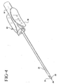
- the catheter introducer 10 of this invention includes an introducer needle 20 and a splittable introducer 50. See FIG. 1.
- introducer needle 20 is initially disposed in splittable introducer 50. See FIG. 5.
- the sharp distal tip 21 of introducer needle 20 extends beyond the distal end 41 of the cannula 60 of splittable introducer 50.
- the needle hub 30 of introducer needle 20 is proximal of the hub 70 of splittable introducer 50.
- Sharp distal tip 21 of introducer needle 20 is formed by grinding a bevel 22 at the distal end of introducer needle 21.
- Bevel 22 has a standard B bevel configuration.
- bevel 22 could be formed having a shorter length than that of a standard B bevel. A shorter bevel length facilitates access to the small veins of certain patients, such as pediatric and neonatal patients, and minimizes the chances that the clinician will pierce the back of the vein during venipuncture
- Introducer needle 20 also includes a notch, or sideport opening, 25 adjacent to sharp distal tip 21.
- Notch 25 is in fluid communication with the lumen 26 that extends from the distal end to the proximal end of introducer needle 20.
- Notch 25 allows blood to flow from inside lumen 26 to the annular space between introducer needle 20 and cannula 60 when catheter introducer 10 of this invention is in the configuration shown in FIG. 5.
- blood will be immediately visible to the clinician in that annular space along the distal portion of catheter introducer 10, as long as cannula 60 is at least translucent.
- introducer needle 20 does not have to wait for the blood to travel along the entire length of introducer needle 20 into the flashback chamber 31, which is preferably integral with needle hub 30, located at the proximal end of the introducer needle 20.
- This immediate indication of successful venipuncture is especially important when the patient has a low blood pressure or low blood flow.
- Needle hub 30 is connected to the proximal end of introducer needle 20 so that the longitudinal axis of introducer needle 20 extends below the center of mass of needle hub 30. Offsetting introducer needle 20 and needle hub 30 in this way allows the clinician to approach the venipuncture site at a low insertion angle because of the small distance between the bottom of introducer needle 20 and the bottom of needle hub 30. Thus, needle hub 30 does not engage the patient's skin until the longitudinal axis of introducer needle 20 is substantially parallel to the patient's skin.
- the insertion angle should be less than about 4° at about one inch of useable needle length. Such a low insertion angle minimizes the chances that the clinician will pierce the back of the vein during venipuncture.
- needle hub 30 since the center of mass of needle hub 30 is located above the longitudinal axis of introducer needle 20, there is a greater surface area on needle hub 30 above introducer needle 20 for the clinician to grasp. This facilitates manipulation of introducer needle 20 by the clinician. Moreover, the bottom of needle hub 30 should not extend significantly below the bottom of the wings 71 of splittable introducer 50. This arrangement ensures that needle hub 30 is not the limiting factor in the insertion angle.
- Splittable introducer 50 includes a cannula 60 and a hub 70 connected to the proximal end of cannula 60.
- Cannula 60 can be formed from any flexible, biocompatible polymer. However, polyethylene or polytetrafluorethylene is preferably used. These materials are translucent and allow blood visualization in the annular space between introducer needle 20 and cannula 60.
- the material for cannula 60 can be loaded with a certain amount of radiopaque material, such as barium sulfate. The radiopaque material allows a clinician to see cannula 60 under a fluoroscope. This is important if cannula 60 were to somehow break off from hub 70 and enter deep into the patient's vasculature. The radiopacity of cannula 60 allows the clinician to identify its location in the body via a fluoroscope and surgically remove it.
- cannula 60 is preferably loaded with stripes of the radiopaque material. This allows at least a significant portion of cannula 60 to remain translucent along its entire length.
- Cannula 60 is formed with a pair of longitudinally extending preferential lines 61 which are about 165° apart.
- Preferential tear lines 61 effectively separate cannula 60 into two pieces. These preferential tear lines 61 allow cannula 60 to be easily split into two pieces when the two portions of cannula 60 are pulled apart by allowing the cannula to be tom along the preferential tear lines 61.
- Preferential tear lines 61 can be formed by scoring cannula 60 to provide a weakened portion to cannula 60.
- Altematively-preferentlal tear lines 61 could be formed by longitudinal molecular orientation of the cannula material along the desired tear lines.
- Hub 70 is located at the proximal end of cannula 60 and is formed with a pair of wings 71 radially extending from a pair of shafts 72. Between each shaft 72 is a groove 72a. Each wing 71 and its associated shaft 72 is aligned on a portion of cannula 60 between each preferential tear line 61 with one of the preferential tear lines 61 located along one groove 72a. This arrangement allows the clinician to pull apart wings 71 and split cannula 60 into two portions along preferential tear lines 61.
- tray 75 Extending between each wing 71 is a tray 75 that extends from the proximal end of cannula 60.
- tray has a generally half-cylindrical configuration continuous with a bottom portion of cannula 60.
- tray 75 has a semi-circutar cross-section with a radius substantially equal to the radius of cannula 60.
- tray 75 has an open top. See FIG. 2a. All that is required is that tray 75 have an open top and a bottom surface configuration that leads into the open proximal end of cannula 60.
- This configuration allows a clinician to automatically align the distal end of a catheter, guidewire or other long, thin and flexible medical device with the open proximal end of cannula 60 for insertion therein by placing the distal end of the medical device onto tray 75.
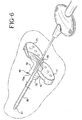
- the clinician can lay the distal portion of the catheter or guidewire along the top groove 72a, see FIG. 6, move the catheter or guidewire proximally until the distal end drops on tray 75, and then advance the catheter or guidewire through the open proximal end of introducer 60, see FIGS. 7 and 9.
- the clinician can drop the distal end of the catheter or guidewire straight down onto tray 75. When the distal end of the catheter or guidewire hits tray 75, the clinician can advance the catheter or guidewire into the open proximal end of introducer 60. See FIG. 8.
- Wings 71 are connected to cannula 60 such that the longitudinal axis of cannula 60 extends below the center of mass of wings 71.
- the longitudinal axis of cannula 60 is arranged such that about 66% of the center of mass of wings 71 extends above the longitudinal axis of cannula 60.
- the longitudinal axis of cannula 60 should be about 0.014 inches below the center of mass of wings 71.
- this arrangement allows the clinician to approach the venipuncture site with a low insertion angle but still provides sufficient surface area above cannula 60 for a clinician to easily manipulate the device.
- the bottom of wings 71 should not extend significantly below the bottom of tray 75. This also allows the clinician to use a low insertion angle because the bottom of the wings will not be the limiting factor in the insertion angle used. Instead tray 75 becomes the limiting factor.
- catheter introducer 10 To use catheter introducer 10, the clinician ensures that it is in the configuration as shown in FIG. 5 with needle bevel 22 facing up and extending distally from the distal end of cannula 60. The clinician approaches the venipuncture site at a low insertion angle and proceeds with the venipuncture. Upon confirmation of blood flashback in the annular space between introducer needle 20 and cannula 60 along the distal portion thereof, the clinician advances cannula 60 further into the vein and removes introducer needle 20. The clinician then places the distal portion of a catheter, guidewire or other long, thin flexible medical device on top of cannula 60 over tray 75.
- the distal portion is then moved proximally until it drops on tray 75 where it is automatically aligned with the open proximal end of cannula 60.
- the clinician can drop the distal end of the catheter, guidewire or other long, thin flexible medical device down onto tray 75 where it will be automatically aligned with the open proximal end of cannula 60.
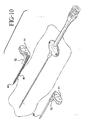
- the long, thin flexible medical device is then advanced distally into position. At that point, the clinician can manipulate wings 71 to split cannula 60 and remove splittable introducer 50 from the patient. See FIG. 10.
- a catheter introducer that facilitates aligning the distal end of a long, thin, flexible medical device with the open proximal end of the cannula without having to approach the open proximal end along a line coincident with the longitudinal axis of the cannula and that allows the clinician to use a low insertion angle with the catheter introducer.
Landscapes
- Health & Medical Sciences (AREA)
- Life Sciences & Earth Sciences (AREA)
- Biophysics (AREA)
- Pulmonology (AREA)
- Engineering & Computer Science (AREA)
- Anesthesiology (AREA)
- Biomedical Technology (AREA)
- Heart & Thoracic Surgery (AREA)
- Hematology (AREA)
- Animal Behavior & Ethology (AREA)
- General Health & Medical Sciences (AREA)
- Public Health (AREA)
- Veterinary Medicine (AREA)
- Media Introduction/Drainage Providing Device (AREA)
Claims (10)
- Kathetereinführvorrichtung (10), die aufweist:eine Einführungskanüle (60) mit einem proximalen Abschnitt, einem offenen proximalen Ende und einem offenen distalen Ende, einem Hohlraum, der sich zwischen dem offenen proximalen Ende und dem offenen distalen Ende erstreckt, einer Längsachse und einem Radius;ein Paar Flügel (71), die einen Schwerpunkt zusammenhängend längs des proximalen Abschnittes der Einführungskanüle (60) aufweisen, so dass der Schwerpunkt von der Längsachse der Einführuagskanüle (60) versetzt ist;eine Mulde (75) mit einer offenen Oberseite, die sich vom offenen proximalen Ende der Einftihrungskanüle (60) zwischen dem Paar der Flügel (71) erstreckt;eine Einführungsnadel (20), die im Hohlraum der Einführungskanüle (60) angeordnet ist und einen ringförmigen Raum mit der Einführungskanüle definiert, wobei die Einführungsnadel (20) eine scharfe distale Spitze (21), ein proximales Ende, eine Längsachse und einen Nadelhohlraum (26) aufweist, der sich zwischen der scharfen distalen Spitze (21) und dem proximalen Ende erstreckt; undeine Nadelnabe (30) mit einem Schwerpunkt zusammenhängend mit dem proximalen Ende der Einführungsnadel (20), so dass der Schwerpunkt von der Längsachse der Nadel (20) versetzt ist;dadurch gekennzeichnet, dass der Boden der Flügel (71) und der Boden der Mulde (75) während der Benutzung auf der Haut des Patienten aufliegen, so dass der Einsetzwinkel, der durch die Einführungskanüle und die Haut des Patienten definiert wird, weniger als 4 Grad beträgt.
- Kathetereinfihrvorrichtung nach Anspruch 1, bei der die Mulde (75) einen halbkreisförmigen Querschnitt mit einem Radius im Wesentlichen gleich dem Radius der Einrührungskanüle (60) aufweist.
- Kathetereinftülrvorrichtung nach Anspruch 1, bei der die Einführungsnadel (20) eine Kerbe (25) definiert, um eine Fluidverbindung zwischen dem ringförmigen Raum und dem Nadelhohlraum (26) bereitzustellen.
- Kathetereinführvorrichtung nach Anspruch 3, bei der der Schwerpunkt der Nadelnabe (30) von der Längsachse der Nadel (20) versetzt ist.
- Kathetereinführvorrichtung nach Anspruch 4, bei der der Schwerpunkt der Nadelnabe (30) über der Längsachse der Nadel (20) ist.
- Kathetereinführvorrichtung nach Anspruch 1, bei der der Schwerpunkt des Paares der Flügel (71) von der Längsachse der Einfuhrungskanüle (60) versetzt ist.
- Kathetereinführvorrichtung nach Anspruch 6, bei der der Schwerpunkt des Paares der Flügel (71) über der Längsachse der Einführungskanüle (60) ist.
- Kathetereinführvorrichtung nach Anspruch 7, bei der sich etwa 66 % der Masse des Paares der Flügel (71) über der Längsachse der Einführungskanüle (60) befindet.
- Kathetereinführvorrichtung nach Anspruch 1, bei der die Einf!1h:rungskanüle (60) ein Paar von sich in Längsrichtung erstreckenden Vorzugsrisslinien (61) umfasst.
- Katheteremführvorriehtung nach Anspruch 9, bei der das Paar der sich in Längsrichtung erstreckenden Vorzugsrisslinien (61) etwa 165° auseinander ist.
Applications Claiming Priority (3)
| Application Number | Priority Date | Filing Date | Title |
|---|---|---|---|
| US08/909,223 US6027480A (en) | 1997-08-11 | 1997-08-11 | Catheter introducer |
| US909223 | 1997-08-11 | ||
| PCT/US1998/015292 WO1999007431A1 (en) | 1997-08-11 | 1998-07-23 | Catheter introducer |
Publications (2)
| Publication Number | Publication Date |
|---|---|
| EP1003586A1 EP1003586A1 (de) | 2000-05-31 |
| EP1003586B1 true EP1003586B1 (de) | 2007-04-25 |
Family
ID=25426842
Family Applications (1)
| Application Number | Title | Priority Date | Filing Date |
|---|---|---|---|
| EP98935969A Expired - Lifetime EP1003586B1 (de) | 1997-08-11 | 1998-07-23 | Kathetereinführvorrichtung |
Country Status (7)
| Country | Link |
|---|---|
| US (2) | US6027480A (de) |
| EP (1) | EP1003586B1 (de) |
| JP (1) | JP3586424B2 (de) |
| AU (1) | AU8510598A (de) |
| DE (1) | DE69837667T2 (de) |
| ES (1) | ES2286853T3 (de) |
| WO (1) | WO1999007431A1 (de) |
Families Citing this family (171)
| Publication number | Priority date | Publication date | Assignee | Title |
|---|---|---|---|---|
| US6213979B1 (en) * | 1997-05-29 | 2001-04-10 | Venetec International, Inc. | Medical line anchoring system |
| US6796976B1 (en) * | 1998-03-06 | 2004-09-28 | Scimed Life Systems, Inc. | Establishing access to the body |
| US6159198A (en) * | 1998-07-16 | 2000-12-12 | Medtronic, Inc. | Introducer system |
| US6572588B1 (en) | 2000-03-10 | 2003-06-03 | Venetec International, Inc. | Medical anchoring system |
| US6558354B1 (en) | 2000-08-04 | 2003-05-06 | Becton Dickinson And Company | Adapter for connecting an introducer needle assembly to a catheter introducer |
| US6582390B1 (en) | 2000-11-08 | 2003-06-24 | Endovascular Technologies, Inc. | Dual lumen peel-away sheath introducer |
| DE10057832C1 (de) | 2000-11-21 | 2002-02-21 | Hartmann Paul Ag | Blutanalysegerät |
| US8641644B2 (en) | 2000-11-21 | 2014-02-04 | Sanofi-Aventis Deutschland Gmbh | Blood testing apparatus having a rotatable cartridge with multiple lancing elements and testing means |
| US6837873B1 (en) * | 2000-12-29 | 2005-01-04 | Medex, Inc. | Method and an apparatus for forming a one-piece introducer |
| US9226699B2 (en) | 2002-04-19 | 2016-01-05 | Sanofi-Aventis Deutschland Gmbh | Body fluid sampling module with a continuous compression tissue interface surface |
| ATE497731T1 (de) * | 2001-06-12 | 2011-02-15 | Pelikan Technologies Inc | Gerät zur erhöhung der erfolgsrate im hinblick auf die durch einen fingerstich erhaltene blutausbeute |
| US9795747B2 (en) | 2010-06-02 | 2017-10-24 | Sanofi-Aventis Deutschland Gmbh | Methods and apparatus for lancet actuation |
| ES2336081T3 (es) | 2001-06-12 | 2010-04-08 | Pelikan Technologies Inc. | Dispositivo de puncion de auto-optimizacion con medios de adaptacion a variaciones temporales en las propiedades cutaneas. |
| US8337419B2 (en) | 2002-04-19 | 2012-12-25 | Sanofi-Aventis Deutschland Gmbh | Tissue penetration device |
| US7041068B2 (en) | 2001-06-12 | 2006-05-09 | Pelikan Technologies, Inc. | Sampling module device and method |
| AU2002312521A1 (en) | 2001-06-12 | 2002-12-23 | Pelikan Technologies, Inc. | Blood sampling apparatus and method |
| US7981056B2 (en) | 2002-04-19 | 2011-07-19 | Pelikan Technologies, Inc. | Methods and apparatus for lancet actuation |
| CA2448681C (en) | 2001-06-12 | 2014-09-09 | Pelikan Technologies, Inc. | Integrated blood sampling analysis system with multi-use sampling module |
| US9427532B2 (en) | 2001-06-12 | 2016-08-30 | Sanofi-Aventis Deutschland Gmbh | Tissue penetration device |
| ATE485766T1 (de) | 2001-06-12 | 2010-11-15 | Pelikan Technologies Inc | Elektrisches betätigungselement für eine lanzette |
| AU2002348683A1 (en) | 2001-06-12 | 2002-12-23 | Pelikan Technologies, Inc. | Method and apparatus for lancet launching device integrated onto a blood-sampling cartridge |
| US6749601B2 (en) * | 2001-08-03 | 2004-06-15 | Scimed Life Systems, Inc. | Protective sleeve for an endoscopic instrument and related method of use |
| USD469870S1 (en) | 2001-09-18 | 2003-02-04 | Volker Niermann | Needle assembly |
| US6887417B1 (en) | 2001-11-05 | 2005-05-03 | Bectondickinson And Company | Catheter sleeve assembly and one step injection molding process for making the same |
| EP1458437B1 (de) * | 2001-12-26 | 2010-03-03 | Yale University | Gefäss-shuntvorrichtung |
| US6692464B2 (en) | 2002-02-28 | 2004-02-17 | Cook, Incorporated | T-fitting for splittable sheath |
| US7229458B2 (en) | 2002-04-19 | 2007-06-12 | Pelikan Technologies, Inc. | Method and apparatus for penetrating tissue |
| US7491178B2 (en) | 2002-04-19 | 2009-02-17 | Pelikan Technologies, Inc. | Method and apparatus for penetrating tissue |
| US7371247B2 (en) | 2002-04-19 | 2008-05-13 | Pelikan Technologies, Inc | Method and apparatus for penetrating tissue |
| US7582099B2 (en) | 2002-04-19 | 2009-09-01 | Pelikan Technologies, Inc | Method and apparatus for penetrating tissue |
| US9795334B2 (en) | 2002-04-19 | 2017-10-24 | Sanofi-Aventis Deutschland Gmbh | Method and apparatus for penetrating tissue |
| US7547287B2 (en) | 2002-04-19 | 2009-06-16 | Pelikan Technologies, Inc. | Method and apparatus for penetrating tissue |
| US7175642B2 (en) | 2002-04-19 | 2007-02-13 | Pelikan Technologies, Inc. | Methods and apparatus for lancet actuation |
| US8784335B2 (en) | 2002-04-19 | 2014-07-22 | Sanofi-Aventis Deutschland Gmbh | Body fluid sampling device with a capacitive sensor |
| US9314194B2 (en) | 2002-04-19 | 2016-04-19 | Sanofi-Aventis Deutschland Gmbh | Tissue penetration device |
| US7717863B2 (en) | 2002-04-19 | 2010-05-18 | Pelikan Technologies, Inc. | Method and apparatus for penetrating tissue |
| US7674232B2 (en) | 2002-04-19 | 2010-03-09 | Pelikan Technologies, Inc. | Method and apparatus for penetrating tissue |
| US7901362B2 (en) | 2002-04-19 | 2011-03-08 | Pelikan Technologies, Inc. | Method and apparatus for penetrating tissue |
| US7892183B2 (en) | 2002-04-19 | 2011-02-22 | Pelikan Technologies, Inc. | Method and apparatus for body fluid sampling and analyte sensing |
| US7226461B2 (en) | 2002-04-19 | 2007-06-05 | Pelikan Technologies, Inc. | Method and apparatus for a multi-use body fluid sampling device with sterility barrier release |
| US7648468B2 (en) | 2002-04-19 | 2010-01-19 | Pelikon Technologies, Inc. | Method and apparatus for penetrating tissue |
| US7297122B2 (en) | 2002-04-19 | 2007-11-20 | Pelikan Technologies, Inc. | Method and apparatus for penetrating tissue |
| US7481776B2 (en) | 2002-04-19 | 2009-01-27 | Pelikan Technologies, Inc. | Method and apparatus for penetrating tissue |
| US7524293B2 (en) | 2002-04-19 | 2009-04-28 | Pelikan Technologies, Inc. | Method and apparatus for penetrating tissue |
| US8702624B2 (en) | 2006-09-29 | 2014-04-22 | Sanofi-Aventis Deutschland Gmbh | Analyte measurement device with a single shot actuator |
| US7291117B2 (en) | 2002-04-19 | 2007-11-06 | Pelikan Technologies, Inc. | Method and apparatus for penetrating tissue |
| US7909778B2 (en) | 2002-04-19 | 2011-03-22 | Pelikan Technologies, Inc. | Method and apparatus for penetrating tissue |
| US7976476B2 (en) | 2002-04-19 | 2011-07-12 | Pelikan Technologies, Inc. | Device and method for variable speed lancet |
| US7485128B2 (en) | 2002-04-19 | 2009-02-03 | Pelikan Technologies, Inc. | Method and apparatus for penetrating tissue |
| US7232451B2 (en) | 2002-04-19 | 2007-06-19 | Pelikan Technologies, Inc. | Method and apparatus for penetrating tissue |
| US7331931B2 (en) | 2002-04-19 | 2008-02-19 | Pelikan Technologies, Inc. | Method and apparatus for penetrating tissue |
| US8579831B2 (en) | 2002-04-19 | 2013-11-12 | Sanofi-Aventis Deutschland Gmbh | Method and apparatus for penetrating tissue |
| US9248267B2 (en) | 2002-04-19 | 2016-02-02 | Sanofi-Aventis Deustchland Gmbh | Tissue penetration device |
| US6740277B2 (en) | 2002-04-24 | 2004-05-25 | Becton Dickinson And Company | Process of making a catheter |
| US7083630B2 (en) * | 2002-08-29 | 2006-08-01 | Scimed Life Systems, Inc. | Devices and methods for fastening tissue layers |
| JP4636881B2 (ja) * | 2002-10-01 | 2011-02-23 | ヴェネテック インターナショナル,インコーポレイテッド | カテーテルの固定装置 |
| US8574895B2 (en) | 2002-12-30 | 2013-11-05 | Sanofi-Aventis Deutschland Gmbh | Method and apparatus using optical techniques to measure analyte levels |
| EP1628567B1 (de) | 2003-05-30 | 2010-08-04 | Pelikan Technologies Inc. | Verfahren und vorrichtung zur injektion von flüssigkeit |
| EP1633235B1 (de) | 2003-06-06 | 2014-05-21 | Sanofi-Aventis Deutschland GmbH | Gerät für die entnahme von körperflüssigkeiten und analyten-nachweis |
| AU2004255154B2 (en) | 2003-06-10 | 2009-08-20 | Lumend, Inc. | Catheter systems and methods for crossing vascular occlusions |
| WO2006001797A1 (en) | 2004-06-14 | 2006-01-05 | Pelikan Technologies, Inc. | Low pain penetrating |
| US7604592B2 (en) | 2003-06-13 | 2009-10-20 | Pelikan Technologies, Inc. | Method and apparatus for a point of care device |
| EP1671096A4 (de) | 2003-09-29 | 2009-09-16 | Pelikan Technologies Inc | Verfahren und apparatur für eine verbesserte probeneinfangvorrichtung |
| US9351680B2 (en) | 2003-10-14 | 2016-05-31 | Sanofi-Aventis Deutschland Gmbh | Method and apparatus for a variable user interface |
| US7822454B1 (en) | 2005-01-03 | 2010-10-26 | Pelikan Technologies, Inc. | Fluid sampling device with improved analyte detecting member configuration |
| EP1706026B1 (de) | 2003-12-31 | 2017-03-01 | Sanofi-Aventis Deutschland GmbH | Verfahren und vorrichtung zur verbesserung der fluidströmung und der probennahme |
| US7578803B2 (en) * | 2004-03-18 | 2009-08-25 | C. R. Bard, Inc. | Multifunction adaptor for an open-ended catheter |
| US7854731B2 (en) | 2004-03-18 | 2010-12-21 | C. R. Bard, Inc. | Valved catheter |
| US7594910B2 (en) | 2004-03-18 | 2009-09-29 | C. R. Bard, Inc. | Catheter connector |
| US7594911B2 (en) | 2004-03-18 | 2009-09-29 | C. R. Bard, Inc. | Connector system for a proximally trimmable catheter |
| US8083728B2 (en) * | 2004-03-18 | 2011-12-27 | C. R. Bard, Inc. | Multifunction adaptor for an open-ended catheter |
| US7094218B2 (en) | 2004-03-18 | 2006-08-22 | C. R. Bard, Inc. | Valved catheter |
| USD532513S1 (en) * | 2004-03-19 | 2006-11-21 | Galt Medical Corporation | Handle for an introducer sheath |
| US7377915B2 (en) | 2004-04-01 | 2008-05-27 | C. R. Bard, Inc. | Catheter connector system |
| JP2007535385A (ja) | 2004-04-30 | 2007-12-06 | シー・アール・バード・インコーポレーテッド | 静脈挿管用の弁付き鞘導入器 |
| WO2006011062A2 (en) | 2004-05-20 | 2006-02-02 | Albatros Technologies Gmbh & Co. Kg | Printable hydrogel for biosensors |
| WO2005120365A1 (en) | 2004-06-03 | 2005-12-22 | Pelikan Technologies, Inc. | Method and apparatus for a fluid sampling device |
| US9775553B2 (en) | 2004-06-03 | 2017-10-03 | Sanofi-Aventis Deutschland Gmbh | Method and apparatus for a fluid sampling device |
| ATE368424T1 (de) * | 2004-10-29 | 2007-08-15 | Depuy Products Inc | Instrumente und kits zum nahtanordnungssystem |
| US8932260B2 (en) | 2004-11-29 | 2015-01-13 | C. R. Bard, Inc. | Reduced-friction catheter introducer and method of manufacturing and using the same |
| US8926564B2 (en) | 2004-11-29 | 2015-01-06 | C. R. Bard, Inc. | Catheter introducer including a valve and valve actuator |
| US9597483B2 (en) | 2004-11-29 | 2017-03-21 | C. R. Bard, Inc. | Reduced-friction catheter introducer and method of manufacturing and using the same |
| US8403890B2 (en) * | 2004-11-29 | 2013-03-26 | C. R. Bard, Inc. | Reduced friction catheter introducer and method of manufacturing and using the same |
| DE102004057785A1 (de) * | 2004-11-30 | 2006-06-01 | Arno Raths | Piercingnadel |
| US8652831B2 (en) | 2004-12-30 | 2014-02-18 | Sanofi-Aventis Deutschland Gmbh | Method and apparatus for analyte measurement test time |
| US7195614B2 (en) * | 2005-01-25 | 2007-03-27 | Spinal Integration, Llc | Methods and apparatus for intraoperative administration of analgesia |
| US20070055204A1 (en) * | 2005-01-25 | 2007-03-08 | Geisler Fred H | Methods and Apparatus for Intraoperative Administration of Analgesia |
| US8162898B1 (en) | 2005-04-18 | 2012-04-24 | Venetec International, Inc. | Venipuncture base plate assembly and method of using same |
| US20060276748A1 (en) * | 2005-05-17 | 2006-12-07 | Infussafe Llc | Infusion monitoring device system and method |
| US7875019B2 (en) | 2005-06-20 | 2011-01-25 | C. R. Bard, Inc. | Connection system for multi-lumen catheter |
| WO2007006055A2 (en) | 2005-07-06 | 2007-01-11 | Vascular Pathways Inc. | Intravenous catheter insertion device and method of use |
| AU2006284629B2 (en) | 2005-08-31 | 2012-01-12 | Venetec International, Inc. | Anchoring system for a catheter |
| EP1988961A4 (de) * | 2005-09-19 | 2011-07-27 | Medical Device Group Inc | Anordnung zur fixierung eines medizinischen schlauchs und anwendungsverfahren |
| US7879013B2 (en) | 2005-12-21 | 2011-02-01 | Venetec International, Inc. | Intravenous catheter anchoring device |
| US8052648B2 (en) * | 2005-12-21 | 2011-11-08 | Venetec International, Inc. | Intravenous catheter anchoring device |
| US9138560B2 (en) | 2006-01-12 | 2015-09-22 | Venetec International, Inc. | Universal catheter securement device |
| KR20090019762A (ko) * | 2006-01-12 | 2009-02-25 | 베네텍 인터내셔널 인코포레이티드 | 만능 카테터 고정장치 |
| US7806873B2 (en) * | 2006-07-13 | 2010-10-05 | Venetec International, Inc. | Intravenous securement device with adhesively interconnected anchoring component and permeable adhesive strip |
| US7922696B2 (en) | 2007-01-24 | 2011-04-12 | Access Scientific, Inc. | Access device |
| USD589143S1 (en) * | 2007-04-02 | 2009-03-24 | Enpath Medical, Inc. | Dilator apparatus |
| EP2155035B1 (de) * | 2007-04-11 | 2019-06-05 | Covidien LP | Endoskopische/laparoskopische einführhülse |
| EP2486880A3 (de) | 2007-04-18 | 2013-01-16 | Access Scientific, Inc. | Zugangsvorrichtung |
| EP3093038B1 (de) | 2007-04-18 | 2019-05-22 | Access Scientific, Inc. | Zugangsvorrichtung |
| JP5139518B2 (ja) | 2007-05-07 | 2013-02-06 | バスキュラー・パスウェイズ・インコーポレイテッド | 静脈カテーテル挿入装置 |
| US8469987B2 (en) * | 2007-08-09 | 2013-06-25 | Senorx, Inc. | Split sheath for trocar assembly |
| US8795326B2 (en) | 2007-10-05 | 2014-08-05 | Covidien Lp | Expanding seal anchor for single incision surgery |
| EP2211971A4 (de) | 2007-10-19 | 2014-09-10 | Bard Inc C R | Einführinstrument mit geformter distaler region |
| USD582542S1 (en) | 2008-03-06 | 2008-12-09 | Spinal Integration, Llc | Guide conduit device |
| WO2009114833A1 (en) | 2008-03-14 | 2009-09-17 | Access Scientific, Inc. | Access device |
| USD601242S1 (en) | 2008-03-14 | 2009-09-29 | Access Scientific, Inc. | Access device |
| WO2009126900A1 (en) | 2008-04-11 | 2009-10-15 | Pelikan Technologies, Inc. | Method and apparatus for analyte detecting device |
| US9480821B2 (en) | 2008-06-30 | 2016-11-01 | Venetec International, Inc. | Anchoring system for a medical article |
| USD600793S1 (en) | 2008-09-10 | 2009-09-22 | Access Scientific, Inc. | Access device |
| USD601243S1 (en) | 2008-09-10 | 2009-09-29 | Access Scientific, Inc. | Access device |
| WO2010081096A2 (en) * | 2009-01-12 | 2010-07-15 | Option 3, Llc | Apparatus and methods for tissue closure |
| US9375169B2 (en) | 2009-01-30 | 2016-06-28 | Sanofi-Aventis Deutschland Gmbh | Cam drive for managing disposable penetrating member actions with a single motor and motor and control system |
| US8394067B2 (en) | 2009-05-21 | 2013-03-12 | C.R. Bard, Inc. | Medical device securement system |
| WO2010151825A1 (en) | 2009-06-26 | 2010-12-29 | C. R. Bard, Inc. | Proximally trimmable catheter including pre-attached bifurcation and related methods |
| US8323249B2 (en) | 2009-08-14 | 2012-12-04 | The Regents Of The University Of Michigan | Integrated vascular delivery system |
| WO2011060197A1 (en) | 2009-11-11 | 2011-05-19 | Venetec International, Inc. | Stabilizing device for an extension set |
| JP6009943B2 (ja) | 2010-02-08 | 2016-10-19 | アクセス サイエンティフィック、インク. | アクセス装置 |
| US9364651B2 (en) | 2010-02-23 | 2016-06-14 | Smiths Medical Asd, Inc. | Adapter with special fitting |
| US8965476B2 (en) | 2010-04-16 | 2015-02-24 | Sanofi-Aventis Deutschland Gmbh | Tissue penetration device |
| US11925779B2 (en) | 2010-05-14 | 2024-03-12 | C. R. Bard, Inc. | Catheter insertion device including top-mounted advancement components |
| US10384039B2 (en) | 2010-05-14 | 2019-08-20 | C. R. Bard, Inc. | Catheter insertion device including top-mounted advancement components |
| US8932258B2 (en) | 2010-05-14 | 2015-01-13 | C. R. Bard, Inc. | Catheter placement device and method |
| US9950139B2 (en) | 2010-05-14 | 2018-04-24 | C. R. Bard, Inc. | Catheter placement device including guidewire and catheter control elements |
| US9872971B2 (en) | 2010-05-14 | 2018-01-23 | C. R. Bard, Inc. | Guidewire extension system for a catheter placement device |
| WO2011146769A2 (en) | 2010-05-19 | 2011-11-24 | Tangent Medical Technologies Llc | Integrated vascular delivery system |
| US8814833B2 (en) | 2010-05-19 | 2014-08-26 | Tangent Medical Technologies Llc | Safety needle system operable with a medical device |
| US8262619B2 (en) | 2010-09-30 | 2012-09-11 | Tyco Healthcare Group Lp | Introducer sheath for catheters |
| DE102011009482B4 (de) | 2011-01-26 | 2020-09-10 | Hans Haindl | Sicherheitskanüle |
| US8690833B2 (en) | 2011-01-31 | 2014-04-08 | Vascular Pathways, Inc. | Intravenous catheter and insertion device with reduced blood spatter |
| WO2012154277A1 (en) | 2011-02-25 | 2012-11-15 | C.R. Bard, Inc. | Medical component insertion device including a retractable needle |
| USD903101S1 (en) | 2011-05-13 | 2020-11-24 | C. R. Bard, Inc. | Catheter |
| US9220833B2 (en) | 2011-06-27 | 2015-12-29 | Smiths Medical Asd, Inc. | Medicament infusion systems |
| US8870238B2 (en) | 2011-06-27 | 2014-10-28 | Smiths Medical Asd, Inc. | Fitting for medicament infusion systems |
| US10086151B2 (en) | 2012-08-06 | 2018-10-02 | Smiths Medical Asd, Inc. | Needle assembly |
| USD699341S1 (en) | 2011-08-31 | 2014-02-11 | Smiths Medical Asd, Inc. | Needle assembly |
| US9861383B2 (en) | 2011-08-31 | 2018-01-09 | Smiths Medical Asd, Inc. | Needle assembly |
| US10737087B2 (en) | 2012-04-17 | 2020-08-11 | Smiths Medical Asd, Inc. | Filling fitting |
| US9161775B1 (en) | 2012-05-08 | 2015-10-20 | Greatbatch Ltd. | Tunneling tool for deliberate placement of an ILR |
| CN108607150B (zh) | 2013-01-30 | 2021-01-12 | 血管通路股份有限公司 | 用于静脉穿刺和导管放置的系统和方法 |
| US9782568B2 (en) | 2013-02-05 | 2017-10-10 | Vascular Pathways, Inc. | Systems and methods for needle and catheter advancement |
| BR112015023297B1 (pt) | 2013-03-15 | 2022-04-26 | Venetec International, Inc | Dispositivo de fixação tendo uma correia e curativo integrados |
| US9566087B2 (en) | 2013-03-15 | 2017-02-14 | Access Scientific, Llc | Vascular access device |
| US9895514B2 (en) | 2014-01-27 | 2018-02-20 | Maddoc Medical Products, Inc. | Medical device securement system and method |
| JP6461174B2 (ja) | 2014-02-04 | 2019-01-30 | アイシーユー・メディカル・インコーポレーテッド | 自己プライミングシステムおよび自己プライミング方法 |
| FR3024366B1 (fr) * | 2014-08-04 | 2023-02-10 | Soft Medical Aesthetics | Dispositif pour l'introduction d'une canule a bout arrondi sous la peau d'un patient |
| WO2016037127A1 (en) | 2014-09-05 | 2016-03-10 | C.R. Bard, Inc. | Catheter insertion device including retractable needle |
| WO2016073954A1 (en) | 2014-11-07 | 2016-05-12 | C. R. Bard, Inc. | Connection system for tunneled catheters |
| US10052489B2 (en) * | 2015-03-23 | 2018-08-21 | Greatbatch Ltd. | Apparatus and method for implanting an implantable device |
| US11027099B2 (en) | 2015-04-30 | 2021-06-08 | Smiths Medical Asd, Inc. | Vascular access device |
| USD903100S1 (en) | 2015-05-01 | 2020-11-24 | C. R. Bard, Inc. | Catheter placement device |
| EP3294380B1 (de) | 2015-05-15 | 2022-03-23 | C. R. Bard, Inc. | Kathetereinführvorrichtung |
| US10159820B2 (en) * | 2016-03-30 | 2018-12-25 | Covidien Lp | Anatomical structure access |
| US10493262B2 (en) | 2016-09-12 | 2019-12-03 | C. R. Bard, Inc. | Blood control for a catheter insertion device |
| JP6953541B2 (ja) | 2017-03-01 | 2021-10-27 | シー・アール・バード・インコーポレーテッドC R Bard Incorporated | カテーテル挿入装置 |
| US11351343B2 (en) | 2017-06-02 | 2022-06-07 | Innovital, Llc | Intravenous access assist device with safety feature |
| ES2985142T3 (es) | 2017-08-23 | 2024-11-04 | Bard Inc C R | Conjuntos de catéter y métodos de los mismos |
| US10569059B2 (en) | 2018-03-01 | 2020-02-25 | Asspv, Llc | Guidewire retention device |
| US11389626B2 (en) | 2018-03-07 | 2022-07-19 | Bard Access Systems, Inc. | Guidewire advancement and blood flashback systems for a medical device insertion system |
| USD921884S1 (en) | 2018-07-27 | 2021-06-08 | Bard Access Systems, Inc. | Catheter insertion device |
| EP3911287B1 (de) | 2019-02-01 | 2025-07-09 | Becton Dickinson and Company | Stabilisierungsvorrichtung, system und verfahren dafür für integrierte katheter |
| DE102019004091B3 (de) | 2019-06-11 | 2020-07-09 | Hans Haindl | Kanüle zur suprapubischen Blasenpunktion |
| JP7721504B2 (ja) | 2019-08-19 | 2025-08-12 | ベクトン・ディキンソン・アンド・カンパニー | 正中線カテーテル配置デバイス |
| US11931148B2 (en) * | 2019-09-10 | 2024-03-19 | Becton, Dickinson And Company | Catheter system to facilitate blood sampling and related methods |
| EP4025288A1 (de) | 2019-09-20 | 2022-07-13 | Bard Peripheral Vascular, Inc. | Vorrichtung zum legen eines intravenösen katheters |
| US11197980B2 (en) | 2019-11-27 | 2021-12-14 | Skydance Vascular, Inc. | Retractable needle catheter delivery apparatus |
| DE102020216328A1 (de) | 2020-12-18 | 2022-06-23 | Uromed Kurt Drews Kg | Suprapubische Kanüle |
| JP7717172B2 (ja) | 2021-02-09 | 2025-08-01 | ジンマー バイオメット シーエムエフ アンド ソラシック,リミティド ライアビリティ カンパニー | 電極を配置するための取り外し可能な分離カニューレ |
Family Cites Families (30)
| Publication number | Priority date | Publication date | Assignee | Title |
|---|---|---|---|---|
| DE2104211B1 (de) * | 1971-01-29 | 1971-12-23 | Fa B Braun, 3508 Melsungen | Punktionskanule zur Einführung eines flexiblen Katheters |
| DE2104226B1 (de) * | 1971-01-29 | 1971-12-02 | Braun Fa B | Vorrichtung zur einf]hrung eines flexiblen katheters |
| BE789131A (fr) * | 1971-09-24 | 1973-03-22 | Extracorporeal Med Spec | Aiguille chirurgicale pour l'execution d'operations medicales |
| US4243050A (en) * | 1977-12-13 | 1981-01-06 | Littleford Philip O | Method for inserting pacemaker electrodes and the like |
| US4166469A (en) * | 1977-12-13 | 1979-09-04 | Littleford Philip O | Apparatus and method for inserting an electrode |
| US4306562A (en) * | 1978-12-01 | 1981-12-22 | Cook, Inc. | Tear apart cannula |
| US4326519A (en) * | 1980-02-21 | 1982-04-27 | Abbott Laboratories | Venipuncture device |
| SE426023B (sv) * | 1981-04-23 | 1982-12-06 | Bengt Gustavsson | Anordning bl a for inforande av katetrar i blodkerl |
| DE3117802A1 (de) * | 1981-05-06 | 1982-11-25 | Max Dr. 8520 Erlangen Hubmann | Katheterbesteck |
| US4345596A (en) * | 1981-12-23 | 1982-08-24 | Janis Marie Young | Arterial catherization device |
| US4449973A (en) * | 1982-06-26 | 1984-05-22 | Luther Medical Products, Inc. | Small gauge, pre-split cannula and process for manufacture |
| ES533509A1 (es) * | 1983-07-18 | 1985-09-01 | Abbott Lab | Conjunto de inyector y cateter para la extraccion intravenosa de sangre. |
| US4596559A (en) * | 1984-11-02 | 1986-06-24 | Fleischhacker John J | Break-away handle for a catheter introducer set |
| US4772266A (en) * | 1987-05-04 | 1988-09-20 | Catheter Technology Corp. | Catheter dilator/sheath assembly and method |
| JPS642662A (en) * | 1987-06-25 | 1989-01-06 | Nippon Sherwood Kk | Easy split plastic cannula excellent in stability |
| US4954130A (en) * | 1988-01-20 | 1990-09-04 | William P. Waters | Catheter/heparin lock and method of using same |
| US5141497A (en) * | 1989-06-06 | 1992-08-25 | Becton, Dickinson And Company | Apparatus and method for an introducer |
| US5098392A (en) * | 1991-06-28 | 1992-03-24 | Fleischhacker John J | Locking dilator for peel away introducer sheath |
| US5125904B1 (en) * | 1991-07-09 | 1996-11-19 | Hl Medical Inventions Inc | Splittable hemostatic valve sheath and the method for using the same |
| US5167634A (en) * | 1991-08-22 | 1992-12-01 | Datascope Investment Corp. | Peelable sheath with hub connector |
| DE4200255A1 (de) * | 1992-01-08 | 1993-07-15 | Sueddeutsche Feinmechanik | Spaltkanuele und verfahren zur herstellung einer solchen |
| US5221263A (en) * | 1992-07-30 | 1993-06-22 | Gesco International, Inc. | Catheter emplacement apparatus |
| US5397311A (en) * | 1992-09-09 | 1995-03-14 | Menlo Care, Inc. | Bloodless splittable introducer |
| US5250033A (en) * | 1992-10-28 | 1993-10-05 | Interventional Thermodynamics, Inc. | Peel-away introducer sheath having proximal fitting |
| US5425717A (en) * | 1993-05-07 | 1995-06-20 | The Kendall Company | Epidural catheter system utilizing splittable needle |
| US5334157A (en) * | 1993-09-09 | 1994-08-02 | Gesco International, Inc. | Catheter introducer |
| US5354281A (en) * | 1994-03-25 | 1994-10-11 | Chen Shih Shuan | Safety disposable infusion set |
| US5536255A (en) * | 1994-10-03 | 1996-07-16 | Moss; Gerald | Dilator/introducer apparatus for percutaneous gastrostomy |
| US5697914A (en) * | 1995-03-16 | 1997-12-16 | Becton Dickinson And Company | Control forward/flashback forward one hand introducer needle and catheter assembly |
| US5743882A (en) * | 1996-03-08 | 1998-04-28 | Luther Medical Products, Inc. | Needle blunting assembly for use with intravascular introducers |
-
1997
- 1997-08-11 US US08/909,223 patent/US6027480A/en not_active Expired - Lifetime
-
1998
- 1998-07-23 AU AU85105/98A patent/AU8510598A/en not_active Abandoned
- 1998-07-23 ES ES98935969T patent/ES2286853T3/es not_active Expired - Lifetime
- 1998-07-23 DE DE69837667T patent/DE69837667T2/de not_active Expired - Lifetime
- 1998-07-23 WO PCT/US1998/015292 patent/WO1999007431A1/en not_active Ceased
- 1998-07-23 EP EP98935969A patent/EP1003586B1/de not_active Expired - Lifetime
- 1998-07-23 JP JP2000507015A patent/JP3586424B2/ja not_active Expired - Lifetime
-
1999
- 1999-12-07 US US09/456,958 patent/US6273871B1/en not_active Expired - Lifetime
Also Published As
| Publication number | Publication date |
|---|---|
| DE69837667D1 (de) | 2007-06-06 |
| JP2002517263A (ja) | 2002-06-18 |
| DE69837667T2 (de) | 2008-01-10 |
| WO1999007431A1 (en) | 1999-02-18 |
| US6027480A (en) | 2000-02-22 |
| US6273871B1 (en) | 2001-08-14 |
| EP1003586A1 (de) | 2000-05-31 |
| JP3586424B2 (ja) | 2004-11-10 |
| AU8510598A (en) | 1999-03-01 |
| ES2286853T3 (es) | 2007-12-01 |
Similar Documents
| Publication | Publication Date | Title |
|---|---|---|
| EP1003586B1 (de) | Kathetereinführvorrichtung | |
| CN219595553U (zh) | 可快速插入中心导管插入组件 | |
| US5328480A (en) | Vascular wire guiode introducer and method of use | |
| US6500157B2 (en) | Intravenous infusion needle with soft body | |
| CA1174929A (en) | Peelable catheter with heat shrink ring and suture sleeve | |
| EP0522735B1 (de) | Verriegelungsdilatator für ablösbare Einführungshülse | |
| AU2001247237B2 (en) | Medical introducer apparatus | |
| US10065025B2 (en) | Over-the-needle guidewire vascular access systems and methods | |
| EP3250278B1 (de) | Integrierter katheter mit schneller einführung | |
| US5205830A (en) | Catheter assembly | |
| US6280433B1 (en) | Introducer system | |
| EP1049510B1 (de) | Vorrichtung zum einführen einer kanüle | |
| EP1196213B1 (de) | System zum einführen von kathetern | |
| US4412832A (en) | Peelable catheter introduction device | |
| JP2024514572A (ja) | 分割可能なアンカーを備えるカテーテル留置システム | |
| EP0162982A2 (de) | Katheterhülle | |
| EP0631793A1 (de) | Auftrennbares hemostatisches Ventil und desser Anwendungsmethode mit einer auftrennbaren Einführungshülse | |
| AU2001247237A1 (en) | Medical introducer apparatus | |
| KR20210151896A (ko) | 삽입기 바늘 및 관련 카테터 삽입 디바이스 | |
| US5913845A (en) | Needle puller/catheter adaptor coupling device | |
| EP0556618B1 (de) | Chirurgischer Dilator | |
| JPH0442949B2 (de) | ||
| WO2000015289A1 (en) | Splittable catheter | |
| EP4138976B1 (de) | Kanülenbrenner und verfahren dafür |
Legal Events
| Date | Code | Title | Description |
|---|---|---|---|
| PUAI | Public reference made under article 153(3) epc to a published international application that has entered the european phase |
Free format text: ORIGINAL CODE: 0009012 |
|
| 17P | Request for examination filed |
Effective date: 20000218 |
|
| AK | Designated contracting states |
Kind code of ref document: A1 Designated state(s): DE ES FR GB IT |
|
| 17Q | First examination report despatched |
Effective date: 20030804 |
|
| GRAP | Despatch of communication of intention to grant a patent |
Free format text: ORIGINAL CODE: EPIDOSNIGR1 |
|
| GRAS | Grant fee paid |
Free format text: ORIGINAL CODE: EPIDOSNIGR3 |
|
| GRAA | (expected) grant |
Free format text: ORIGINAL CODE: 0009210 |
|
| AK | Designated contracting states |
Kind code of ref document: B1 Designated state(s): DE ES FR GB IT |
|
| REG | Reference to a national code |
Ref country code: GB Ref legal event code: FG4D |
|
| REF | Corresponds to: |
Ref document number: 69837667 Country of ref document: DE Date of ref document: 20070606 Kind code of ref document: P |
|
| ET | Fr: translation filed | ||
| REG | Reference to a national code |
Ref country code: ES Ref legal event code: FG2A Ref document number: 2286853 Country of ref document: ES Kind code of ref document: T3 |
|
| PLBE | No opposition filed within time limit |
Free format text: ORIGINAL CODE: 0009261 |
|
| STAA | Information on the status of an ep patent application or granted ep patent |
Free format text: STATUS: NO OPPOSITION FILED WITHIN TIME LIMIT |
|
| 26N | No opposition filed |
Effective date: 20080128 |
|
| REG | Reference to a national code |
Ref country code: FR Ref legal event code: PLFP Year of fee payment: 19 |
|
| REG | Reference to a national code |
Ref country code: FR Ref legal event code: PLFP Year of fee payment: 20 |
|
| PGFP | Annual fee paid to national office [announced via postgrant information from national office to epo] |
Ref country code: GB Payment date: 20170620 Year of fee payment: 20 Ref country code: FR Payment date: 20170621 Year of fee payment: 20 |
|
| PGFP | Annual fee paid to national office [announced via postgrant information from national office to epo] |
Ref country code: IT Payment date: 20170621 Year of fee payment: 20 |
|
| PGFP | Annual fee paid to national office [announced via postgrant information from national office to epo] |
Ref country code: ES Payment date: 20170803 Year of fee payment: 20 Ref country code: DE Payment date: 20170620 Year of fee payment: 20 |
|
| REG | Reference to a national code |
Ref country code: DE Ref legal event code: R071 Ref document number: 69837667 Country of ref document: DE |
|
| REG | Reference to a national code |
Ref country code: GB Ref legal event code: PE20 Expiry date: 20180722 |
|
| PG25 | Lapsed in a contracting state [announced via postgrant information from national office to epo] |
Ref country code: GB Free format text: LAPSE BECAUSE OF EXPIRATION OF PROTECTION Effective date: 20180722 |
|
| REG | Reference to a national code |
Ref country code: ES Ref legal event code: FD2A Effective date: 20210129 |
|
| PG25 | Lapsed in a contracting state [announced via postgrant information from national office to epo] |
Ref country code: ES Free format text: LAPSE BECAUSE OF EXPIRATION OF PROTECTION Effective date: 20180724 |