US10569059B2 - Guidewire retention device - Google Patents
Guidewire retention device Download PDFInfo
- Publication number
- US10569059B2 US10569059B2 US15/942,217 US201815942217A US10569059B2 US 10569059 B2 US10569059 B2 US 10569059B2 US 201815942217 A US201815942217 A US 201815942217A US 10569059 B2 US10569059 B2 US 10569059B2
- Authority
- US
- United States
- Prior art keywords
- guidewire
- locking mechanism
- dilator
- access device
- stop
- Prior art date
- Legal status (The legal status is an assumption and is not a legal conclusion. Google has not performed a legal analysis and makes no representation as to the accuracy of the status listed.)
- Active
Links
Images


Classifications
-
- A—HUMAN NECESSITIES
- A61—MEDICAL OR VETERINARY SCIENCE; HYGIENE
- A61M—DEVICES FOR INTRODUCING MEDIA INTO, OR ONTO, THE BODY; DEVICES FOR TRANSDUCING BODY MEDIA OR FOR TAKING MEDIA FROM THE BODY; DEVICES FOR PRODUCING OR ENDING SLEEP OR STUPOR
- A61M25/00—Catheters; Hollow probes
- A61M25/01—Introducing, guiding, advancing, emplacing or holding catheters
- A61M25/09—Guide wires
-
- A—HUMAN NECESSITIES
- A61—MEDICAL OR VETERINARY SCIENCE; HYGIENE
- A61M—DEVICES FOR INTRODUCING MEDIA INTO, OR ONTO, THE BODY; DEVICES FOR TRANSDUCING BODY MEDIA OR FOR TAKING MEDIA FROM THE BODY; DEVICES FOR PRODUCING OR ENDING SLEEP OR STUPOR
- A61M25/00—Catheters; Hollow probes
- A61M25/01—Introducing, guiding, advancing, emplacing or holding catheters
- A61M25/06—Body-piercing guide needles or the like
- A61M25/0606—"Over-the-needle" catheter assemblies, e.g. I.V. catheters
-
- A—HUMAN NECESSITIES
- A61—MEDICAL OR VETERINARY SCIENCE; HYGIENE
- A61M—DEVICES FOR INTRODUCING MEDIA INTO, OR ONTO, THE BODY; DEVICES FOR TRANSDUCING BODY MEDIA OR FOR TAKING MEDIA FROM THE BODY; DEVICES FOR PRODUCING OR ENDING SLEEP OR STUPOR
- A61M25/00—Catheters; Hollow probes
- A61M25/01—Introducing, guiding, advancing, emplacing or holding catheters
- A61M25/06—Body-piercing guide needles or the like
- A61M25/065—Guide needles
-
- A—HUMAN NECESSITIES
- A61—MEDICAL OR VETERINARY SCIENCE; HYGIENE
- A61M—DEVICES FOR INTRODUCING MEDIA INTO, OR ONTO, THE BODY; DEVICES FOR TRANSDUCING BODY MEDIA OR FOR TAKING MEDIA FROM THE BODY; DEVICES FOR PRODUCING OR ENDING SLEEP OR STUPOR
- A61M25/00—Catheters; Hollow probes
- A61M25/01—Introducing, guiding, advancing, emplacing or holding catheters
- A61M25/09—Guide wires
- A61M25/09041—Mechanisms for insertion of guide wires
-
- A—HUMAN NECESSITIES
- A61—MEDICAL OR VETERINARY SCIENCE; HYGIENE
- A61M—DEVICES FOR INTRODUCING MEDIA INTO, OR ONTO, THE BODY; DEVICES FOR TRANSDUCING BODY MEDIA OR FOR TAKING MEDIA FROM THE BODY; DEVICES FOR PRODUCING OR ENDING SLEEP OR STUPOR
- A61M29/00—Dilators with or without means for introducing media, e.g. remedies
-
- A—HUMAN NECESSITIES
- A61—MEDICAL OR VETERINARY SCIENCE; HYGIENE
- A61M—DEVICES FOR INTRODUCING MEDIA INTO, OR ONTO, THE BODY; DEVICES FOR TRANSDUCING BODY MEDIA OR FOR TAKING MEDIA FROM THE BODY; DEVICES FOR PRODUCING OR ENDING SLEEP OR STUPOR
- A61M25/00—Catheters; Hollow probes
- A61M25/01—Introducing, guiding, advancing, emplacing or holding catheters
- A61M25/06—Body-piercing guide needles or the like
- A61M25/0662—Guide tubes
- A61M2025/0681—Systems with catheter and outer tubing, e.g. sheath, sleeve or guide tube
-
- A—HUMAN NECESSITIES
- A61—MEDICAL OR VETERINARY SCIENCE; HYGIENE
- A61M—DEVICES FOR INTRODUCING MEDIA INTO, OR ONTO, THE BODY; DEVICES FOR TRANSDUCING BODY MEDIA OR FOR TAKING MEDIA FROM THE BODY; DEVICES FOR PRODUCING OR ENDING SLEEP OR STUPOR
- A61M25/00—Catheters; Hollow probes
- A61M25/01—Introducing, guiding, advancing, emplacing or holding catheters
- A61M25/06—Body-piercing guide needles or the like
- A61M25/0662—Guide tubes
- A61M2025/0687—Guide tubes having means for atraumatic insertion in the body or protection of the tip of the sheath during insertion, e.g. special designs of dilators, needles or sheaths
-
- A—HUMAN NECESSITIES
- A61—MEDICAL OR VETERINARY SCIENCE; HYGIENE
- A61M—DEVICES FOR INTRODUCING MEDIA INTO, OR ONTO, THE BODY; DEVICES FOR TRANSDUCING BODY MEDIA OR FOR TAKING MEDIA FROM THE BODY; DEVICES FOR PRODUCING OR ENDING SLEEP OR STUPOR
- A61M25/00—Catheters; Hollow probes
- A61M25/01—Introducing, guiding, advancing, emplacing or holding catheters
- A61M25/09—Guide wires
- A61M2025/09125—Device for locking a guide wire in a fixed position with respect to the catheter or the human body
-
- A—HUMAN NECESSITIES
- A61—MEDICAL OR VETERINARY SCIENCE; HYGIENE
- A61M—DEVICES FOR INTRODUCING MEDIA INTO, OR ONTO, THE BODY; DEVICES FOR TRANSDUCING BODY MEDIA OR FOR TAKING MEDIA FROM THE BODY; DEVICES FOR PRODUCING OR ENDING SLEEP OR STUPOR
- A61M25/00—Catheters; Hollow probes
- A61M25/01—Introducing, guiding, advancing, emplacing or holding catheters
- A61M25/09—Guide wires
- A61M2025/09175—Guide wires having specific characteristics at the distal tip
- A61M2025/09183—Guide wires having specific characteristics at the distal tip having tools at the distal tip
-
- A—HUMAN NECESSITIES
- A61—MEDICAL OR VETERINARY SCIENCE; HYGIENE
- A61M—DEVICES FOR INTRODUCING MEDIA INTO, OR ONTO, THE BODY; DEVICES FOR TRANSDUCING BODY MEDIA OR FOR TAKING MEDIA FROM THE BODY; DEVICES FOR PRODUCING OR ENDING SLEEP OR STUPOR
- A61M25/00—Catheters; Hollow probes
- A61M25/01—Introducing, guiding, advancing, emplacing or holding catheters
- A61M25/06—Body-piercing guide needles or the like
- A61M25/0662—Guide tubes
- A61M25/0668—Guide tubes splittable, tear apart
Definitions
- the present disclosure is generally directed to access devices for introducing and/or delivering a medical article (such as, for example, a catheter, cannula, sheath, etc.) into a body space, such as, for example, an artery, vein, vessel, body cavity, or drainage site, and more specifically, to devices which include structure for interlocking or engaging with a guidewire.
- a medical article such as, for example, a catheter, cannula, sheath, etc.
- a body space such as, for example, an artery, vein, vessel, body cavity, or drainage site
- a preferred non-surgical method for inserting a catheter or vascular sheath into a blood vessel involves the use of the Seldinger or a modified Seldinger technique, which includes an access needle that is inserted into a patient's blood vessel.
- a guidewire is inserted through the needle and into the vessel.
- the needle is removed, and a dilator and sheath in combination or separately are then inserted over the guidewire.
- the dilator and sheath, together or separately, are then inserted a short distance through the tissue into the vessel, after which the dilator and guidewire are removed and discarded.
- a catheter or other medical article may then be inserted through the sheath into the vessel to a desired location, or the sheath may simply be left in the vessel.
- the above technique requires exchanges over the guidewire, which presents the risk of losing cannulation, lost guidewire, and contamination.
- the overall technique is time intensive risking movement of the medical article(s) and guidewire relative to the patient.
- the access devices described herein advantageously provide improved mechanisms for safely achieving medical device placement within the vasculature. Without limiting the scope of this disclosure, its more prominent features will be discussed briefly. After considering this discussion, and particularly after reading the Detailed Description of the Preferred Embodiments section below in combination with this section, one will understand how the features and aspects of these embodiments provide several advantages over prior access devices.
- the access device for placing a medical article within a body space.
- the access device includes a dilator having a hub and an elongated dilator body extending from the hub.
- the access device further includes a guidewire configured to slide within the dilator body and having a guidewire stop.
- the access device further includes a locking mechanism supported by the dilator and having a guidewire lock. The locking mechanism being configured to interlock with the guidewire at least when the dilator is threaded over the guidewire and the guidewire lock axially aligns with the guidewire stop.
- the access device for placing a medical article within a body space.
- the access device includes a guidewire having a guidewire stop and a dilator configured to be coaxially disposed about the guidewire.
- the access device further includes a locking mechanism disposed on the dilator and configured to move from an unlocked state to a locked state.
- the locking mechanism is disengaged from the guidewire when the locking mechanism is in the unlocked state so as to allow axial movement by the guidewire through the locking mechanism in a proximal direction and a distal direction.
- the locking mechanism is engaged with the guidewire when the locking mechanism is in the locked state so as to limit at least axial movement of a portion of the guidewire in the distal direction relative to at least a portion of the dilator.
- Yet another aspect is a method of limiting a distance a guidewire can be advanced out of a distal end of a dilator and into a patient's body.
- the method includes puncturing a patient's body with a needle having an interior bore, sliding a guidewire through the interior bore and into the patient's body, and removing the needle from the patient's body.
- the method further comprises threading a dilator over the guidewire and into the patient's body.
- the dilator includes a locking mechanism configured to receive the guidewire and interlock to the guidewire so as to inhibit at least relative axial movement between at least a portion of the guidewire and at least a portion of the dilator in one direction.
- the locking mechanism may comprise an attachment connecting to at least one area of the guidewire so that the guidewire cannot be inadvertently advanced too far into the patient, resulting in intravascular guidewire loss or embolization.
- the locking mechanism can be configured to maintain a maximum guidewire length beyond the needle tip when advanced.
- the locking mechanism can be configured to retain the guidewire to the access device so that the guidewire is not misplaced or lost in the patient's body.
- the locking mechanism limits the extent to which the guidewire can be moved (e.g., advanced) relative to the needle.
- a groove or recess can be disposed at a proximal region of the guidewire to inhibit the proximal region from disengaging from the locking mechanism and entering the patient.
- the groove or recess can be positioned at other locations along the guidewire to help regulate the length of guidewire that can be advanced from the needle tip.
- an interaction e.g., interference, engagement, friction, mechanical coupling, adhesion, etc.
- an interaction exists between the guidewire and the locking mechanism to inhibit relative movement between these components.
- FIG. 1 is a perspective view of an embodiment of an access device including a dilator coaxially aligned with a sheath. A guidewire is also shown.
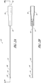
- FIG. 2A is side view of a needle which can be employed to facilitate insertion of the guidewire of FIG. 1 into a patient.
- FIG. 2B is a side cross-sectional view of the needle of FIG. 2A taken along line 2 B- 2 B.
- FIG. 3A is a plan view of the dilator of the access device of FIG. 1 and includes a locking mechanism.
- FIG. 3B is a side cross-sectional view of the dilator of FIG. 3A taken along the lines 3 B- 3 B.
- FIG. 4A is an enlarged view of a portion of the dilator of FIG. 3A which is circled by line 4 A- 4 A.
- the dilator includes a receptacle configured to receive the locking mechanism.
- FIG. 4B is a cross-sectional view of the dilator of FIG. 4A taken along line 4 B- 4 B of FIG. 4C .
- FIG. 4C is an end view of the dilator of FIG. 4A looking in a distal direction.
- FIG. 5A is a proximal end view of the sheath of the access device of FIG. 1 .
- FIG. 5B is a side view of the sheath of FIG. 5A .
- FIG. 6 is a cross-sectional view of the access device of FIG. 1 after the access device has been threaded over the guidewire.
- FIG. 7A is a view of a proximal region of an embodiment of the guidewire depicted in FIG. 1 showing a guidewire stop configured to be used by a locking mechanism to secure to the guidewire.
- FIG. 7B is a view of a proximal region of another embodiment of the guidewire depicted in FIG. 1 showing a guidewire stop configured to be used by a locking mechanism to secure to the guidewire.
- FIG. 8 is a front perspective view of the locking mechanism of FIG. 4A removed from the dilator.
- FIG. 9 is a rear perspective view of the locking mechanism from FIG. 8 .
- FIG. 10 is a front perspective view of the locking mechanism of FIG. 8 in an open state to allow a guidewire to pass through the locking mechanism as the dilator and the sheath are being threaded over the guidewire.
- FIG. 11 is a rear perspective view of the locking mechanism of FIG. 10 in a locked state where the dilator and the sheath is further threaded over the guidewire until the locking mechanism interlocks with the guidewire stop on the guidewire.
- FIG. 11A is an enlarged partial side view of the locking mechanism of FIG. 11 interlocked with the guidewire stop of FIG. 7A on the guidewire.
- FIG. 11B is an enlarged partial side view of the locking mechanism of FIG. 11 interlocked with the guidewire stop of FIG. 7B on the guidewire.
- FIG. 12A is a side cross-sectional view of the needle of FIG. 2A penetrating a body.
- FIG. 12B is an enlarged side cross-sectional view of a distal end of the needle of FIG. 12A which is circled by line 12 B- 12 B.
- FIG. 13A is a side cross-sectional view of the needle of FIG. 12A where the needle has penetrated the vasculature.
- FIG. 13B is an enlarged side cross-sectional view of a distal end of the needle of FIG. 13A which is circled by line 13 B- 13 B.
- FIG. 14 is a side cross-sectional view of the needle of FIG. 13A where a guidewire has been fed through the needle and into the vasculature of the patient.
- FIG. 15 is a side cross-sectional view of the needle of FIG. 14 where the guidewire has been extended into the vasculature of the patient.
- FIG. 16A is a side cross-sectional view of the dilator and the sheath of FIG. 1 that have been slid along the exterior portion of the guidewire of FIG. 15 until the locking mechanism in the dilator interlocks with the guidewire stop.
- FIG. 16B is an enlarged side cross-sectional view of a portion of the dilator and the sheath of from FIG. 16A which is circled by line 16 B- 16 B.
- FIG. 16C is an enlarged side cross-sectional view of a portion of the dilator and the sheath similar to FIG. 16B , where the orientation of the locking mechanism is reversed.
- FIG. 17 is a side cross-sectional view of the dilator and the sheath of FIG. 16A where the dilator and sheath have been slid further along the exterior portion of the guidewire and into the patient's vasculature causing the dilator to be spaced from the locking mechanism.
- FIG. 18 is a side cross-sectional view of the dilator and the sheath of FIG. 17 where the guidewire and interlocked locking mechanism have been withdrawn from the dilator and the sheath.
- FIG. 19 is a side cross-sectional view of the dilator and the sheath of FIG. 18 where the dilator has been withdrawn from the patient and the sheath.
- FIG. 20 is a side cross-sectional view of the sheath of FIG. 19 where a catheter is aligned with the sheath for insertion into the patient's vasculature.
- FIG. 21 is a side cross-sectional view of the sheath of FIG. 20 where the catheter has been inserted through the sheath and into the patient's vasculature.
- FIG. 22 is a side cross-sectional view of the sheath of FIG. 21 where two portions of the sheath are being peeled away from each other to remove the sheath from encircling the catheter.
- FIG. 23A is a front view of an embodiment of a locking mechanism.
- FIG. 23B is a rear view of the locking mechanism of FIG. 23A .
- FIG. 23C is a side cross-sectional view of the locking of FIG. 23A taken along the lines 23 C- 23 C.
- FIG. 24A is a side cross-sectional view of the locking mechanism of FIG. 23A with a guidewire inserted through the locking mechanism.
- FIG. 24B is a side cross-sectional view of the locking mechanism of FIG. 24A interlocked with the guidewire.
- FIG. 25A is a front view of an embodiment of a locking mechanism.
- FIG. 25B is a side cross-sectional view of the locking of FIG. 25A taken along the lines 25 B- 25 B.
- FIG. 26A is a side cross-sectional view of the locking mechanism of FIG. 25A adhered to a dilator with a guidewire inserted through the locking mechanism.
- FIG. 26B is a side cross-sectional view of the locking mechanism of FIG. 25A interlocked with the guidewire.
- FIG. 27A is a side cross-sectional view of an embodiment of a locking mechanism engaged with a dilator and having a guidewire inserted through the locking mechanism.
- FIG. 27B is a side cross-sectional view of the locking mechanism of FIG. 27A interlocked with the guidewire.
- FIG. 28A is a front view of an embodiment of a locking mechanism.
- FIG. 28B is a rear view of the locking mechanism of FIG. 28A .
- FIG. 28C is a side cross-sectional view of the locking of FIG. 28A taken along the lines 28 C- 28 C.
- FIG. 29A is a side cross-sectional view of the locking mechanism of FIG. 28A located within a dilator and having a guidewire inserted through the locking mechanism.
- FIG. 29B is a side cross-sectional view of the locking mechanism of FIG. 29A interlocked with the guidewire.
- FIG. 1 illustrates an access device 20 that is configured to be inserted into a blood vessel (e.g., a vein or an artery) in accordance with an embodiment discussed herein. While the access device is described below in this context (i.e., for vascular access), the access device also can be used to access and place a medical article (e.g., catheter or sheath) into other locations within a patient's body (e.g., a drainage site) and for other purposes (e.g., for draining an abscess).
- a medical article e.g., catheter or sheath
- the access device in some embodiments, is disclosed in the context of placing an exemplary single-piece, tubular medical article into a body space within a patient. Once placed, the tubular article can then be used to receive other medical articles (e.g., catheters, guidewires, etc.) to provide access into the body space and/or be used to provide a passage way for introducing fluids into the body space or removing (e.g., draining) fluids from the body space.
- the tubular medical article can be a sheath or catheter that is configured primarily to provide a fluid passage into a vein.
- the current disclosure should not be interpreted as being limited to the placement of single piece sheaths or catheters, or to the subsequent insertion of a medical article via the sheath or catheter. Instead, it will be understood by one of skill in this art, in light of the current disclosure, that the access device disclosed herein also can be successfully utilized in connection with placing one or more other types of medical articles, including other types of sheaths, fluid drainage and delivery tubes, and single or multi-lumen catheters directly in the patient or indirectly via another medical article.
- the access device disclosed herein can be configured to directly or indirectly place central venous catheters, peripherally inserted central catheters, hemodialysis catheters, surgical drainage tubes, tear-away sheaths, multi-piece sheaths, scopes, as well as electrical conduit for wires or cables connected to external or implanted electronic devices or sensors.
- the medical articles listed herein may be directly placed in the patient via the dilator and guidewire of the access device or subsequently placed within the patient via a medical article that was placed within the patient via the dilator and guidewire of the access device.
- the embodiments disclosed herein are not limited to co-axial insertion of a single medical article.
- two catheters may be inserted in the patient via an inserted sheath or a second catheter may be inserted in the patient via an inserted first catheter.
- the medical article inserted via the dilator and guidewire can form a lumen that is in addition to the lumen(s) of the subsequently inserted medical article.
- One skilled in the art can also find additional applications for the devices and systems disclosed herein.
- the illustration and description of the access device in connection with a sheath is merely exemplary of one possible application of the access device.
- FIG. 1 is a perspective view of an embodiment of an access device 20 that includes a dilator 24 coaxially aligned with a sheath 26 .
- a guidewire 28 is also shown.
- the components of the access device 20 illustrated in FIG. 1 include a dilator 24 and a sheath 26 .
- the access device 20 also includes the guidewire 28 .
- the sheath 26 can be coaxially mounted on the dilator 24 .
- the telescoping nature of the access device's components can also be accomplished by arranging the components with their axes arranged substantially parallel rather than coaxially (e.g., a monorail-type design).
- each of these components includes a luminal fitting at a terminal end or transition (e.g., a hub) and elongated structure that extends from the fitting.
- the dilator 24 includes a dilator shaft 36 that extends distally from a dilator hub 38
- the sheath 26 includes a sheath body 40 that extends distally from a sheath hub 42 .
- the guidewire 28 includes a guidewire hub or cap.
- the access device 20 further includes a stopper or locking mechanism 30 .
- the locking mechanism 30 provides one or more interlocks or interconnections between the locking mechanism 30 and the guidewire and/or one or more other components of the access device 20 .
- the locking mechanism 30 provides a first interlock between the locking mechanism 30 and the guidewire 28 .
- the locking mechanism 30 further provides a second interlock between the locking mechanism 30 and another component of the access device 20 .
- the first and second interlocks of the locking mechanism 30 can engage with the guidewire 28 and the dilator 24 , respectively.
- the locking mechanism 30 need not include both first and second interlocks.
- the locking mechanism 30 further locks to another component of the access device 20 .
- the locking mechanism 30 can include an interlock for locking to the sheath 26 .
- interlock means a feature of the locking mechanism 30 which inhibits movement of the locking mechanism 30 in at least one direction relative a component of the access device 20 .
- An interlock can be an interaction (e.g., interference, engagement, friction, mechanical coupling, mechanical interconnection, mechanical interplay, adhesion, etc.).
- such features include one or more structures of the locking mechanism 30 such as tabs, teeth, grooves, etc. as well as a size or shape of the locking mechanism 30 itself.
- an outer portion of the locking mechanism 30 could be sized and shaped so as to inhibit movement of the locking mechanism 30 relative to an inner surface of a component of the access device 20 via contact between the outer portion and the inner surface.
- the locking mechanism 30 is configured to inhibit a proximal portion of the guidewire 28 from being advanced too far through the dilator 24 . Advancing the guidewire 28 beyond a proximal end of the dilator 24 risks the possibility of intravascular guidewire loss. Further, even if the guidewire 28 is not advanced beyond the proximal end of the dilator 24 , when the dilator 24 is withdrawn from the sheath 26 there is a risk that any friction occurring between flowing blood and a portion of the guidewire 28 inserted into the vasculature will draw the guidewire 28 into the vasculature. In certain embodiments, the locking mechanism 30 allows the guidewire 28 to be withdrawn from the access device 20 generally simultaneously with the dilator 24 .
- an advanced guidewire 28 is inhibited from being withdrawn back into the dilator 24 .
- the interlock between the locking mechanism 30 and the guidewire 28 can inhibit proximal and/or distal movement of the guidewire 28 relative to the dilator 24 .
- Such an arrangement can reduce the risk of breaking off a distal end of the guidewire 28 and having the distal end of the guidewire 28 enter the vasculature.
- FIG. 2A is side view of a needle 22 which can be employed to facilitate insertion of the guidewire 28 from FIG. 1 into a patient.
- FIG. 2B is a side cross-sectional view of the needle 22 of the embodiment depicted in FIG. 2A taken along line 2 B- 2 B.
- the needle 22 includes a needle body 32 and a needle hub 34 .
- the needle hub 34 is disposed on a proximal end of the needle body 32 .
- the needle body 32 terminates at a distal end near a distal portion 48 of the needle 22
- the needle hub 34 lies at a proximal portion 50 of the needle 22 .
- the needle body 32 preferably has an elongated tubular shape having a circular, constant-diameter interior bore 54 and a circular, constant-diameter exterior surface. In other embodiments, however, the needle body 32 can have other bore and exterior shapes (such as, for example, but without limitation, an oval cross-sectional shape).
- the interior or exterior of the needle 22 can also include grooves or channels. The grooves or channels may guide fluids within the needle bore either around or to certain structures of the needle 22 or within the needle 22 (e.g., around the guidewire 28 ). In some embodiments, the grooves or channels may assist in maintaining a desired orientation of the needle 22 with respect to the dilator 24 .
- the needle body 32 has a sufficiently long length to access a targeted subcutaneous body space and has a sufficient gauge size to withstand the insertion forces when accessing the body space without causing undue trauma.
- the needle body 32 can have a length between 3-20 cm (e.g., between 3-10 cm).
- the needle body 32 preferably has a length of 7 cm or greater, and more preferably has a length of 9 cm or greater, and most preferably has a length of 9 to 10 cm.
- the size of the needle 22 preferably is 18 gauge or smaller (e.g., between 18-28 gauge or between 18-26 gauge for micro-puncture applications (peripheral IVs)).
- the length and gauge of the needle body 32 should be significantly shorter and smaller, for example between 3-4 cm and between 26-28 gauge.
- the needle body 32 can have a bevel tip 52 disposed on the distal portion 48 .
- the guidewire 28 is introduced through a hollow portion 68 of the needle hub 34 , through the needle body 32 , and into a punctured vessel. After removing the needle 22 from the patient, the remaining guidewire 28 allows the healthcare provider to guide the dilator 24 and sheath 26 into the vessel.
- FIG. 3A is a plan view of a dilator 24 that can be used with the access device 20 of FIG. 1 and includes a locking mechanism 30 .
- FIG. 3B is a side cross-sectional view taken along the lines 3 B- 3 B in FIG. 3A .
- the illustrated dilator 24 comprises a dilator shaft 36 , a dilator hub 38 , a distal region 70 , and a proximal region 72 .
- FIG. 4A is an enlarged view of a portion of the dilator 24 illustrated in FIG. 4A which is circled by line 4 A- 4 A.
- the dilator 24 includes a receptacle 74 .
- the receptacle is configured to receive the locking mechanism 30 .
- the locking mechanism 30 need not reside within the dilator 24 .
- the locking mechanism 30 resides on top of the dilator 24 or outside the dilator 24 as long as the guidewire 28 passes through the locking mechanism 30 .
- the receptacle 74 is sized and shaped so as to allow the locking mechanism 30 to be housed in the dilator hub 38 .
- the locking mechanism 30 may be removed from the receptacle 74 after interlocking with the guidewire 28 .
- the locking mechanism 30 can be removably engaged with at least a portion of the dilator hub 38 so that the locking mechanism 30 can move in or out of the receptacle 74 when the dilator hub 38 is slid in a proximal or distal direction, respectively, along the guidewire 28 .
- the locking mechanism 30 may be removably held within the receptacle 74 via any suitable interaction (e.g., interference, engagement, friction, mechanical coupling, adhesion, etc.).
- any suitable interaction e.g., interference, engagement, friction, mechanical coupling, adhesion, etc.
- the locking mechanism 30 interlocks with the guidewire 28 so that the guidewire 28 and locking mechanism 30 move in unison during removal of the guidewire 28 .
- further proximal movement of the guidewire 28 relative to the dilator 24 may be sufficient to overcome the interactive force removably holding the locking mechanism 30 within the receptacle 74 .
- the locking mechanism 30 may be removed from the receptacle 74 after the locking mechanism 30 is engaged to the guidewire 28 by applying a continuing pulling force to move the guidewire 28 in a proximal direction relative to the dilator 24 .
- one or more walls such as bottom surface 58 of the receptacle 74 prevent distal movement of the locking mechanism 30 relative to the receptacle 74 .
- FIG. 4B is a cross-sectional view of the dilator 24 depicted in FIG. 4A taken along line 4 B- 4 B of FIG. 4C .
- FIG. 4C is an end view of the dilator 24 depicted in FIG. 4A looking in a distal direction.
- the dilator hub 38 may include locking structures at the proximal region 72 and the distal region 70 of the dilator 24 .
- Each locking structure may be a luer type or other type of connection.
- the dilator hub 38 comprises a luer connection 78 .
- the luer connection 78 e.g., a male luer slip connector
- the sheath hub 42 e.g., a female luer slip connector
- the male-female lure slip connectors on these components can be reversed.
- the color of the dilator 24 may be selected to enhance the contrast between the blood or other fluid and the dilator 24 .
- blood is observed flowing between the dilator 24 and the sheath 26 to confirm proper placement in a blood vessel.
- the sheath 26 is preferably manufactured from a clear or transparent material with the dilator 24 having a color that contrasts with the color of the fluid.
- the dilator 24 may have a white color to enhance its contrast with red blood.
- Other colors of dilator 24 could be employed depending on the color of the fluid and the degree of contrast desired. Further, only a portion of the dilator 24 in the region of the blood flash can have the contrasting color with the remainder having a different color.
- the dilator 24 expands an opening or passage created by the needle 22 .
- the expanded passage facilitates subsequent introduction of the sheath 26 .
- the needle 22 allows the introduction of the guidewire 28 , and subsequently the dilator 24 and finally the sheath 26 into a patient's body.
- FIG. 5A is an end view of a sheath 26 that can be used with the access device 20 of FIG. 1 .
- FIG. 5B is a side view of the sheath 26 depicted in FIG. 5A .
- the sheath 26 may comprise a sheath body 40 , a sheath hub 42 , a distal region 86 , and a proximal region 88 .
- the sheath body 40 may be made partially or completely from clear, translucent, transparent, or semi-opaque material.
- the sheath body 40 can also include one or more radiopaque markers, such as, for example, barium sulfate stripes. In a preferred embodiment, the sheath includes two such radiopaque stripes disposed on diametrically opposite sides of the body 40 .
- the sheath body 40 may be a single piece sheath through which a catheter or other medical article is inserted into the vessel.
- the sheath body 40 forms a conduit for insertion of the catheter or other medical article.
- the sheath 26 or a portion of the sheath can form a lumen that is in addition to the lumen(s) of the catheter.
- an equivalent to a triple lumen catheter can be formed by inserting a dual lumen catheter through the sheath body 40 with the sheath body 40 itself forming a third lumen.
- a peel-away sheath can include perforations, serrations, skives, or other structures, or include other materials (e.g., PTFE with bismuth) to allow the physician or healthcare provider to remove easily a portion or the entire sheath body 40 .
- the sheath hub 42 may include a luer slip connection 90 .
- the luer slip connection 90 may comprise a locking or attaching structure that mates or engages with a corresponding structure.
- the luer slip connection 90 can be configured to engage with the luer connection 78 of the dilator hub 38 .
- the sheath hub 42 preferably is designed so that the luer connection 78 of the dilator hub 38 can enter the sheath hub 42 substantially unobstructed.
- the physician or healthcare provider can push, pull, or twist the sheath hub 42 and possibly disengage or engage the luer slip connection 90 with a corresponding connector on another medical article.
- the luer slip connection 90 creates a mechanical fit so that the dilator hub 38 and the sheath hub 42 are releasably interlocked.
- the sheath hub 42 preferably engages with the corresponding luer connection 78 on the dilator hub 38 .
- the locked position can be disengaged or engaged by pulling, squeezing, pushing or twisting the dilator hub 38 relative to the sheath hub 42 .
- the sheath hub 42 may comprise radially extending wings or handle structures to allow for easy release and removal of the sheath body 40 from other parts of the access device 20 .
- the wings are sized to provide the healthcare provider with leverage for breaking apart the sheath hub 42 .
- the sheath hub 42 may comprise a thin membrane connecting the halves of the sheath hub 42 . The membrane is sized to keep the halves of the sheath hub 42 together until the healthcare provider decides to remove the sheath hub 42 from the access device. The healthcare provider manipulates the wings to break the membrane and separate the sheath hub 42 into removable halves.
- FIG. 6 is a side cross-sectional view of the access device 20 depicted in FIG. 1 after the access device 20 has been threaded over the guidewire 28 .
- the dilator 24 includes the dilator shaft 36 that extends distally from the dilator hub 38
- the sheath 26 includes the sheath body 40 that extends distally from the sheath hub 42 .
- the guidewire 28 includes a guidewire hub or cap (not shown).
- the dilator 24 and the sheath 26 are releasably interlocked at a proximal end of the access device 20 .
- the releasable interlock between the dilator 24 and the sheath 26 is a linear interlock where the sheath 26 is locked to the dilator 24 .
- the relative positioning of the terminal ends of the dilator 24 and the sheath 26 are shown in FIG. 6 .
- the terminal end of the dilator body 36 extends beyond the terminal end of the sheath 26 .
- FIGS. 7A and 7B are various views of a proximal region 94 of the guidewire 28 depicted in FIG. 1 showing a guidewire stop 92 A, 92 B configured to be used by the locking mechanism 30 to secure to the guidewire 28 .
- the guidewire stop 92 A, 92 B is one or more features of the guidewire 28 which allow the locking mechanism 30 to engage the guidewire 28 .
- the guidewire stop 92 A is in the form of an annular groove defined by one or more ridges (e.g., two ridges). The groove may be sized and configured to engage with the corresponding locking mechanism 30 , as described herein.
- the guidewire stop 92 A is illustrated as a groove, it will be understood by one having skill in the art that the guidewire stop may comprise any shape or size suitable to engage the locking mechanism 30 .
- the guidewire stop 92 B may comprise an outward protrusion configured to inhibit further distal movement of the guidewire 28 relative to the locking mechanism 30 once the guidewire stop 92 B abuts and/or engages the locking mechanism 30 .
- the guidewire stop 92 B may function in a similar manner as the guidewire stop 92 A.
- the guidewire stop 92 B may comprise one or more outward protrusions (e.g. cams) protruding from on one or more sides of the guidewire 28 .
- the one or more cams may be sized and configured to separate the opposing clips 80 (as described herein and shown in FIGS. 8 and 9 ) of the locking mechanism 30 as the one or more cams pass through the opposing clips 80 in a proximal direction relative to the locking mechanism 30 . After the one or more cams pass through the opposing clips 80 , the opposing clips 80 may close behind the one or more cams to prevent distal movement of the one or more cams relative to the opposing clips 80 .
- guidewire stop 92 A, 92 B is illustrated as residing on the proximal region 94 of the guidewire 28 , it will be understood by one having skill in the art that the guidewire stop 92 A, 92 B may be placed at any location along the guidewire 28 . In certain other embodiments, the guidewire stop is in the form of a notch, taper, barb, adhesive, magnet, or other feature.
- the guidewire stop 92 A, 92 B can be formed by varying the width of the guidewire 28 .
- the guidewire 92 B may comprise a portion of the guidewire 28 that comprises an increased width relative to the remainder of the guidewire 28 .
- the increased width portion of the guidewire stop 92 B may be followed by a guidewire 28 section of reduced width that is located both proximal and distal to the guidewire stop 92 B.
- the increased width of the guidewire stop 92 B may be sized and configured to permit the locking mechanism 30 to engage the guidewire stop 92 B, while also being of a sufficient width to inhibit the guidewire stop 92 B from passing through the opening 82 of the locking mechanism 30 , described herein.
- the increased width of the guidewire stop 92 B can be configured to engage the locking mechanism 30 , while also permitting the guidewire stop 92 B to pass through the interior bore 54 of the needle 22 .
- an outer width of the guidewire stop 92 B may be smaller than an interior diameter of the interior bore 54 of the needle 22 .
- the increased width of the guidewire stop 92 B may be formed by any suitable means.
- the guidewire stop 92 B may comprise an annular flange located along the guidewire 28 .
- the guidewire stop 92 B may be formed by stamping and/or compressing a portion of the guidewire 28 to form a guidewire stop 92 that comprises a pinched surface with an outwardly protruding increased width along the guidewire 28 .
- the guidewire stop 92 A, 92 B is preferably disposed in the proximal region 94 of the guidewire 28 and is configured to engage with the locking mechanism 30 at least when the dilator 24 is threaded over the guidewire 28 .
- the healthcare provider can freely manipulate the guidewire 28 within the dilator 24 .
- the healthcare provider is prevented from extending the guidewire 28 further in a distal direction relative to the dilator 24 .
- the locking mechanism 30 closes about the outer surface of the guidewire 28 so as to pinch the guidewire 28 .
- the pinching force in some instances, may not be sufficient to engage with the guidewire 28 .
- the bite force of the locking mechanism 30 on the guidewire 28 is insufficient to prevent movement of the guidewire 28 relative to the locking mechanism 30 .
- the bite force of the locking mechanism 30 on the guidewire 28 may still permit movement of the guidewire 28 relative to the locking mechanism 30 until the locking mechanism 30 interlocks or engages with the guidewire stop 92 A, 92 B.
- the locking mechanism 30 may not sufficiently resist passage of the guidewire 28 through the locking mechanism 30 before the locking mechanism 30 engages the guidewire stop 92 A, 92 B. Once the locking mechanism 30 engages with the guidewire stop 92 A, 92 B, the locking mechanism 30 inhibits at least further distal movement of the guidewire 28 relative to the locking mechanism 30 .
- FIG. 8 is a perspective view of the locking mechanism 30 from FIG. 4A removed from the dilator 36 .
- FIG. 9 is an opposite end perspective view of the locking mechanism 30 from FIG. 8 .
- the dilator hub 38 comprises the locking mechanism 30 .
- the locking mechanism 30 is disposed in the sheath 26 or other medical article.
- the locking mechanism 30 may be configured to lock or secure to the guidewire 28 .
- the locking mechanism 30 comprises a guidewire lock 44 and an opening 82 .
- the guidewire lock 44 can comprise one or more engaging mechanisms such as a pair of opposing clips, teeth, tabs, or opening, although other types of locking mechanisms comprising tabs and/or slots can also be used.
- the guidewire lock 44 is configured as a pair of opposing clips 80 .
- the locking mechanism 30 is generally V-shaped and is configured to be biased towards a closed condition, while still permitting the locking mechanism 30 to slide over the guidewire 28 when the guidewire 28 is advanced through the V-shaped locking mechanism 30 and then to spring towards the guidewire 28 and into the guidewire stop 92 A, 92 B.
- FIG. 10 is a view similar to FIG. 8 except the guidewire lock 44 is open or in an unlocked state, allowing the guidewire 28 to pass through the locking mechanism 30 as the dilator 24 and the sheath 26 are threaded over the guidewire 28 .
- the guidewire lock 44 can be biased towards a closed configuration as illustrated in FIG. 8 .
- the degree of bias of the guidewire lock 44 towards the closed condition is selected so that the guidewire 28 can slide through the guidewire lock 44 when the guidewire lock 44 is not in contact or engaged with the guidewire stop 92 A, 92 B.
- the guidewire lock 44 is in a locked state when the guidewire lock 44 is engaged with the guidewire stop 92 A, 92 B (as illustrated in FIGS. 11, 11A, and 11B ).
- FIG. 11 is a view similar to FIG. 10 but taken from the opposite end of the locking mechanism 30 and with the dilator 24 and the sheath 26 further threaded over the guidewire 28 until the locking mechanism 30 interlocks with the guidewire stop 92 A, 92 B on the guidewire 28 .
- FIG. 11A is an enlarged partial cross-section view from FIG. 11 of the locking mechanism 30 interlocked with the guidewire stop 92 A on the guidewire 28 .
- FIG. 11B is an enlarged partial cross-section view from FIG. 11 of the locking mechanism 30 interlocked with the guidewire stop 92 B on the guidewire 28 .
- the locking mechanism 30 has slid in the distal direction relative to the guidewire 28 until the locking mechanism 30 interlocks with the guidewire stop 92 A, 92 B on the guidewire 28 .
- the clips 80 of the guidewire lock 44 can engage a lipped and/or compressed surface such as the guidewire stop 92 A, 92 B shown in FIG. 7 .
- the guidewire lock 44 inhibits the guidewire stop 92 A, 92 B from undesired slipping or releasing relative to the locking mechanism 30 .
- the guidewire 28 can essentially carry the locking mechanism 30 and move in unison with the locking mechanism 30 .
- the guidewire lock 44 is hinged to provide a bias towards the center of the dilator hub 38 . The bias may prevent the secured part of the guidewire 28 from slipping or disengaging from the guidewire lock 44 .
- the interlocking structure illustrated in FIGS. 8-11 is but one example of the types of cooperating structure that can be included to interconnect or interlock the locking mechanism 30 with the guidewire 28 and/or the dilator 24 .
- the interlocking structure in some embodiments, does not engage with the guidewire 28 until the dilator 24 is sufficiently threaded over the guidewire 28 to allow the interlocking structure to contact the guidewire lock 44 . In this way, the interlocking structure does not inhibit use or appreciably increase contact friction when the healthcare provider is manipulating the guidewire 28 until after the guidewire lock 44 contacts the guidewire stop 92 A, 92 B.
- FIGS. 27A and 27B are various views of the locking mechanism 30 and dilator hub 38 , according to some embodiments. At least a portion of the locking mechanism 30 (e.g., the opposing clips 80 A, 80 B shown in FIG. 27A ), in some instances, may be engaged with a portion of the dilator hub 38 to initially maintain the locking mechanism 30 in the open state. As shown in FIGS. 27A and 27B , respectively, the locking mechanism 30 may have a first open state positioned on the dilator hub 38 and a second closed state positioned on and/or engaged with the guidewire 28 .
- the locking mechanism 30 may have a first open state positioned on the dilator hub 38 and a second closed state positioned on and/or engaged with the guidewire 28 .
- the locking mechanism 30 when the locking mechanism 30 is in the open state, the locking mechanism 30 may be placed along a portion of the dilator hub 38 .
- the locking mechanism 30 can be clamped, preformed, or otherwise positioned over or around at least a portion of the dilator hub 38 to temporarily maintain the locking mechanism 30 in the open state and inhibit the locking mechanism 30 from entering the closed state.
- An interior surface of the dilator hub 38 may comprise a ledge, groove, ride, or any suitable protrusion configured to engage one or more of the opposing clips 80 A, 80 B to hold the locking mechanism 30 in the open state before interaction with the guidewire stop.
- the protrusion can be sized and configured to extend along any portion and/or length of the receptacle 74 of the dilator hub 38 .
- the protrusion can be configured to be positioned within the receptacle 74 on a distal end or proximal end of the dilator hub 38 .
- the dilator hub 38 may include one or more ledges 76 A, 76 B configured to engage a corresponding clip 80 A, 80 B.
- the protrusion can be configured such that a first portion of the locking mechanism 30 (e.g., a first clip 80 A) is positioned along a corresponding portion of the protrusion (e.g., a first ledge 76 A), and a second portion of the locking mechanism 30 (e.g., a second clip 80 B) is positioned along a corresponding second portion of the protrusion (e.g., a second ledge 76 B) to maintain the locking mechanism 30 in the open state.
- the locking mechanism 230 can be configured to interlock, engage or adhere to the protrusion when initially positioned within the receptacle 74 .
- the first portion and the second portion of the locking mechanism 30 can adhere at least to the protrusion comprising an adhesive.
- the adhesive can extend along an entire inner perimeter of the protrusion.
- the protrusion can be made of a single unitary body (e.g., an annular ridge) within the dilator hub 38 to that is configured to allow the opposing clips 80 A. 80 B to position themselves over and/or around the one or more ledges 76 A, 76 B to temporarily maintain the locking mechanism 30 in the open state.
- the locking mechanism 30 can comprise an opening 82 (as shown in FIGS. 8-11 ) that is sized and configured to selectively permit at least a portion of the guidewire 28 to pass through.
- the opening 82 can be chamfered to facilitate insertion of the guidewire proximal end through opening 82 .
- An inner diameter of the opening 82 as described herein, can be sufficiently large to permit a portion of the guidewire 28 to reside within and/or pass through the opening 82 . However, in some embodiments, the inner diameter of the opening 82 is not large enough to permit at least another portion of the guidewire 28 to pass through the opening 282 (e.g., the guidewire stop 92 B).
- the guidewire stop 92 B may generally be too large to fit through the opening 82 and further proximal movement of the guidewire 28 relative to the dilator hub 38 will cause the locking mechanism 30 to transition into the closed state.
- the guidewire stop 92 B can abut against the locking mechanism 30 and cause the locking mechanism 30 to move in a proximal direction relative to the dilator hub 38 and, consequently, detach the one or more clips 80 A, 80 B from the protrusion (e.g., one or more ledges 76 A, 76 B) of the dilator hub 38 , as described with reference to FIG. 27B .
- the locking mechanism 30 when the locking mechanism 30 transitions from the open state to the closed state, the locking mechanism 30 can be positioned around a portion of the guidewire 28 such that the locking mechanism 30 prevents the guidewire 28 from moving distally beyond the dilator hub 38 .
- the guidewire stop 92 B can abut against and/or engage the locking mechanism 30 . Further distal movement of the guidewire stop 92 B relative to the dilator hub 38 can cause the guidewire stop 92 B to detach the locking mechanism 30 from the protrusion of the dilator hub 38 .
- Removal of the locking mechanism 30 from the protrusion may cause the locking mechanism 30 to transition to the closed state and engage at least a portion of the guidewire 28 (shown in FIG. 27B ).
- the first clip 80 A and/or the second clip 80 B of the locking mechanism 30 once removed from the protrusion of the dilator hub 38 , may engage the guidewire 28 to enclose at least a portion of the guidewire 28 .
- the locking mechanism 30 can enclose the guidewire 28 to inhibit access of the engaged portion of the guidewire 28 in a distal direction beyond the dilator hub 38 , as described herein.
- the locking mechanism 30 as described herein, can be biased towards the close state so that when in the locking mechanism 30 is disengaged with the protrusion, the locking mechanism 30 automatically transitions towards the closed state (as illustrated in FIG. 27B ).
- annular bead can be located within the dilator hub 38 and biased towards a closed configuration. Once the guidewire stop 92 A, 92 B contacts the guidewire lock 44 , the bead snaps closed about guidewire 28 .
- the dilator hub 38 can include one or more annular grooves defined within the receptacle 74 . When the bead reaches the annular groove the bead and guidewire 28 are prevented from further distal movement.
- the locking mechanism 30 may comprise one or more finger or tang or cam elements defining the guidewire lock 44 or opening configured to permit the guidewire 28 to pass through the locking mechanism 30 .
- the one or more finger elements can project from a distal end of the locking mechanism 30 toward a proximal end of the locking mechanism 30 .
- the one or more finger elements may permit the guidewire stop 92 A, 92 B to pass through the guidewire lock 44 or the opening in a proximal direction but inhibit to passage of the guidewire stop 92 A, 92 B through the guidewire lock 44 or the opening in a distal direction.
- the guidewire stop 92 A, 92 B can slide through the opening in a proximal direction through the finger elements.
- the finger elements can lock into a biased closed position between the guidewire lock 44 or the opening and the guidewire stop 92 A, 92 B. This inhibits and/or substantially irreversibly prevents axial movement of the guidewire stop 92 A, 92 B at least in the distal direction once the guidewire stop 92 A, 92 B passes through the opening.
- the degree of bias of the locking mechanism 30 towards the closed condition is selected so that the guidewire 28 can slide through the locking mechanism 30 when the locking mechanism 30 is not in contact with the guidewire stop 92 .
- the healthcare provider can generally simultaneously withdraw the dilator 24 and the guidewire 28 from the sheath 26 without risking the embolization of the guidewire 28 .
- the engagement of the locking mechanism 30 with the guidewire 28 and/or the dilator 24 can occur through simple axial movement of the guidewire 28 relative to the dilator hub 38 , as understood from the embodiments described above.
- FIG. 12A is a cross-sectional view of the needle 22 illustrated in FIG. 2A penetrating a body 118 .
- FIG. 12B is an enlarged partial cross-sectional view from FIG. 12A of a distal end of the needle 22 .
- the needle 22 has penetrated the vasculature.
- FIG. 13B is an enlarged partial cross-sectional view from FIG. 13A of a distal end of the needle 22 .
- the bevel tip 52 enters the blood vessel 122 .
- FIG. 14 is a cross-sectional view similar to FIG. 13A where a guide wire 28 has been fed through the needle 22 and into the blood vessel 122 of the patient.
- the physician or healthcare provider feeds the guidewire 28 into the vasculature.
- the needle 22 is held still while the guidewire 28 is fed through the needle 22 and into the patient.
- the guidewire 28 passes through the interior bore 54 of the needle 22 .
- a guide wire advancer as known in the art may be employed when feeding the guidewire 28 through the needle 22 .
- an advancer may be employed to straighten the tip facilitating feeding of the guidewire 28 into the interior bore 54 of the needle 22 .
- FIG. 15 is a cross-sectional view similar to FIG. 14 except the guidewire 28 has been extended further into the vasculature of the patient.
- FIG. 16A is a cross-sectional view similar to FIG. 15 where the needle 22 has been removed and the dilator 24 and the sheath 26 have been slid along the exterior portion of the guidewire 28 until the locking mechanism 30 in the dilator 24 interlocks with the guidewire stop 92 A, 92 B.
- FIG. 16B is an enlarged partial cross-sectional view from FIG. 16A .
- the locking mechanism 30 within the receptacle 74 of the dilator 24 has effectively slid in the distal direction relative to the guidewire 28 until the locking mechanism 30 interlocks with the guidewire stop 92 on the guidewire 28 .
- the clips 80 of the guidewire lock 44 can engage a lipped surface such as the guidewire stop 92 A, 92 B shown in FIGS. 7A and 7B . Once engaged, the guidewire lock 44 prevents the locked part of the guidewire 28 from undesired slipping or releasing relative to the locking mechanism 30 .
- the guidewire 28 can essentially carry the locking mechanism 30 and move in unison with the locking mechanism 30 .
- the guidewire lock 44 is hinged to provide a bias towards the center of the dilator hub 38 . The bias can prevent the secured part of the guidewire 28 from slipping or disengaging from the guidewire lock 44 .
- FIG. 16C is an enlarged partial cross-sectional view similar to FIG. 16B , except where the opposing clips 80 of the locking mechanism 30 (as described herein) are located in a proximal direction from the opening 82 of the locking mechanism 30 . While in a reversed orientation (shown in FIG. 16C ), the locking mechanism 30 may function in the same manner as described herein; however, the guidewire 28 and the guidewire stop 92 A, 92 B may pass through the opening 82 prior to passing through or engaging the opposing clips 80 , respectively.
- the guidewire stop 92 A, 92 B and the opening 82 may be sized and configured to permit the guidewire stop 92 A, 92 B to pass through the opening 82 .
- the distal side of opening 82 can be chamfered.
- FIG. 17 is a cross-sectional view similar to FIG. 16A where the dilator 24 and sheath 26 have been slid further along the exterior portion of the guidewire 28 and into the patient's vasculature causing the dilator 24 to be spaced from the locking mechanism 30 .
- the guidewire 28 freely slides through the locking mechanism 30 until the guidewire lock 44 interlocks with the guidewire stop 92 A, 92 B. Once interlocked, the guidewire 28 and the locking mechanism 30 can move in unison. In this configuration, the guidewire 28 is prevented from exiting a distal end of the dilator 24 in a distal direction and being lost in the patient.
- FIG. 18 is a cross-sectional view similar to FIG. 17 where the guidewire 28 and interlocked locking mechanism 30 have been withdrawn from the dilator 24 and the sheath 26 .
- the healthcare provider can instead withdraw the dilator 24 until the locking mechanism 30 contacts or interlocks with the dilator 24 .
- the locking mechanism 30 Prior to removing the guidewire 28 , the locking mechanism 30 can interlock with the dilator 24 by abutting the wall 58 . Accordingly, further withdrawal of the dilator 24 will also withdraw the locking mechanism 30 and the guidewire 28 from the sheath 26 .
- FIG. 19 is a cross-sectional view similar to FIG. 18 where the dilator 24 has been removed from the patient and the sheath 26 .
- the sheath 26 is left properly inserted within the blood vessel 122 .
- the dilator 24 may be removed after or in concert with removal of the guidewire 28 .
- FIG. 20 is a cross-sectional view similar to FIG. 19 where a catheter 120 is aligned with the sheath 26 for insertion into the patient's vasculature.
- FIG. 21 is a cross-sectional view similar to FIG. 20 where the catheter 120 has been inserted through the sheath 26 and into the patient's vasculature, specifically the targeted blood vessel 122 .
- FIG. 21 is a cross-sectional view similar to FIG. 20 where two portions of the sheath 26 are being peeled away from each other to remove the sheath 26 from encircling the catheter 120 .
- the sheath 26 is splittable along one or more split lines.
- a splittable sheath 26 provides the advantage of allowing a portion of or the entire sheath body 40 to be removed depending on the type of catheter or medical article that is to be inserted into the vessel after employing the access device 20 . For example, after the catheter 120 is inserted into the blood vessel 122 , a portion of the sheath body 40 is separated or peeled-away and removed to reduce clutter at the access site.
- the peel-away sheath 26 can be first slid in a proximal direction along the catheter 120 until the sheath 26 is removed from the patient and then split apart. Alternatively, the sheath 26 can be initially split prior to the entire sheath 26 being removed from the patient. After the remainder of the sheath 26 is removed from the patient, the physician or healthcare provided can continue splitting the sheath 26 . Of course, the sheath 26 could be split in concert with its removal from the patient as is illustrated in FIG. 22 . In certain embodiments, the sheath 26 is not splittable.
- FIGS. 23A-24B are various views of a locking mechanism to engage the guidewire 28 , according to some embodiments.
- FIG. 23A is a front view of an embodiment of a locking mechanism 130
- FIGS. 23B and 23C are rear and side cross-sectional views of the locking mechanism 130 , respectively.
- FIGS. 24A and 24B are side cross-sectional views of an embodiment of a method of engaging the locking mechanism 130 with a guidewire 28 including a guidewire stop 92 B.
- the locking mechanism 130 as shown in FIGS. 23A-24B may include components that are the same as or generally similar to the components in the remaining figures discussed herein, as identified by similar reference numerals. It will be understood that the features described with reference to locking mechanism 130 shown in FIGS.
- the locking mechanism 130 may comprise a sphere including an external wall 132 .
- the locking mechanism 130 may be hollow in order to receive at least a portion of the guidewire 28 within an internal cavity 134 of the locking mechanism.
- the locking mechanism 130 may comprise one or more openings. A user may utilize the one or more openings to permit a guidewire 28 to pass through the locking mechanism 130 and engage a guidewire stop 92 B within the internal cavity 134 to prevent unintended removal of the locking mechanism 130 from the guidewire 28 .
- the locking mechanism 130 can comprise an elastomeric material and/or flexible structure capable of slight deformation as the guidewire stop 92 B passes through the one or more openings of the locking mechanism 130 .
- a first opening may function as a guidewire lock 144 , as described herein.
- a second opening 182 may allow a portion of the guidewire 28 proximal to the guidewire stop 92 B to pass through and/or exit the internal cavity 134 of the locking mechanism 130 , while still maintaining a portion of the guidewire 28 (e.g., the guidewire stop 92 B) within the internal cavity 134 .
- the openings may be located on opposite sides of the external wall 132 .
- the first opening or locking element 144 may be located at a distal end of the locking mechanism 130 .
- the opening of the locking element 144 may not comprise a constant diameter along the entire length of the external wall 132 of the locking mechanism 130 (as shown in FIG. 23C ).
- the locking element 144 may include an external opening 146 and an internal opening 148 of varying diameters that extend through the external wall 132 .
- a diameter of the external opening 146 of the locking element 144 can be larger than a diameter of the internal opening 148 of the locking element 144 .
- the locking element 144 may taper towards the internal opening 148 .
- the tapering may advantageously permit the guidewire stop 92 B to pass through the locking element 144 only in a proximal direction and into the internal cavity 134 , while inhibiting the guidewire stop 92 B from passing through the locking element 144 in a distal direction once the guidewire stop d 92 B has been inserted into the internal cavity 144 .
- the locking element 144 can comprise any suitable shape and configuration capable of receiving and/or engaging the guidewire stop 92 B.
- the locking element 144 can comprise a generally conical shape, although it will be appreciated that the locking element 144 can comprise any suitable wall structure (e.g., straight and/or curved) and have any suitable shape (e.g., cylindrical, tapered).
- the diameter of the external opening 146 may be larger than the guidewire 28 (e.g., including the guidewire stop 92 B), but the diameter of the internal opening 148 may be smaller than at least the guidewire stop 92 B.
- the diameter of the internal opening 148 can be smaller than the outer width or diameter of the guidewire stop 92 B, but sufficiently large so that the external wall 132 defining the internal opening 148 can temporarily resiliently or flexibly increase in size to permit the guidewire stop 92 B to pass through the internal opening 148 in a proximal direction and into the internal cavity 134 , while inhibiting removal of the guidewire stop 92 B in a distal direction from the internal cavity 134 once inserted.
- FIG. 24B show that, in some embodiments, both the second opening 182 and the internal opening 148 can each comprise an internal diameter smaller than an external width of an outer surface of the guidewire stop 92 B to prevent the unintended removal of the guidewire stop 92 B from the internal cavity 134 in a distal and/or proximal direction. Accordingly, the second opening 182 and the internal opening 148 may be sized to permit only portions of the guidewire 28 that are located distal and/or proximal to the guidewire stop 92 B to extend outside of the internal cavity 134 , while the guidewire stop 92 B remains contained inside of the internal cavity 134 .
- the locking element 144 can comprise any suitable shape and/or configuration capable of permitting the guidewire stop 92 B to access the internal cavity 134 of the locking mechanism 130 , while resisting removal of the guidewire stop 92 B from within the internal cavity 134 .
- the external wall 132 may comprise any material suitable to permit engagement with the guidewire 28 without causing the locking mechanism 130 to tear or irreversibly stretch or otherwise be damaged upon passage of the guidewire stop 92 B through the internal opening 148 .
- the locking mechanism 130 can comprise a semi-rigid or resilient or elastomeric material capable of slight deformation when a force is applied.
- the internal opening 148 can be configured to deform radially outward or in an opening direction that is generally perpendicular to the longitudinal axis of the guidewire stop 92 B.
- the internal opening 148 can be configured to rebound radially inward in a closing direction, generally opposite from the opening direction, after the guidewire stop 92 B is inserted into the internal cavity 134 (as shown in FIG. 24B ). This may advantageously allow the internal opening 148 of the locking element 144 to temporarily and/or permanently retain the guidewire stop 92 B within the internal cavity 134 .
- FIGS. 25A-26B are various views of another locking mechanism to engage the guidewire 28 , according to some embodiments.
- FIG. 25A is a front view of an embodiment of a locking mechanism 230
- FIG. 25B is a side cross-sectional view of the locking mechanism 230
- FIGS. 26A and 26B are side cross-sectional views of an embodiment of a method of engaging the locking mechanism 230 with a guidewire 28 including a guidewire stop 92 B.
- the locking mechanism 230 as shown in FIGS. 25A-26B may include components that are the same as or generally similar to the components in the remaining figures discussed herein, as identified by similar reference numerals. It will be understood that the features described with reference to locking mechanism 230 shown in FIGS.
- 25A-26B can be used with any of the embodiments described and/or contemplated herein. It will also be understood that any feature, structure, material, step, or component of any embodiment described and/or illustrated herein can be used with or instead of any other feature, structure, material, step, or component of any embodiment of locking mechanism 230 shown in FIGS. 25A-26B .
- the locking mechanism 230 can comprise a sheath or disc that is configured to interact with at least a portion of the guidewire 28 (e.g., the guidewire stop 92 B), as shown in FIGS. 26A and 26B .
- the locking mechanism 230 as described herein, can be folded, wrapped, or otherwise positioned over or around the guidewire 28 to enclose at least a portion of the guidewire stop 92 B, or otherwise interact with the guidewire stop 92 B, to inhibit the locking mechanism 230 and the guidewire stop 92 A from moving in a distal direction beyond the dilator hub 38 (e.g., into the dilator shaft).
- the locking mechanism 230 can be made of a single unitary body that can fold, be folded, be wrapped, or otherwise automatically position itself over or around, be positioned over or around, or be folded over or around the dilator hub 38 and/or the guidewire 28 to inhibit unintentional distal movement of the guidewire 28 relative to the dilator hub 38 .
- the locking mechanism 230 may have a first configuration positioned on the proximal portion 72 of the dilator hub 38 and a second configuration positioned on and engaged with the guidewire 26 .
- the locking mechanism 230 when the locking mechanism is in the first configuration, the locking mechanism 230 may be placed along a proximal portion 72 of the dilator hub 38 .
- the locking mechanism 230 can be sized and configured to extend along and enclose any portion and/or length of the receptacle 74 of the dilator hub 38 .
- the locking mechanism 230 can be configured to be positioned over and enclose the receptacle 74 on a proximal end of the proximal portion 72 of the dilator hub 38 .
- the locking mechanism 230 can be configured such that a first portion 244 a of the locking mechanism is positioned along a corresponding first portion of the dilator hub 38 , and a second portion 244 b of the locking mechanism 230 is positioned along a corresponding second portion of the dilator hub 38 to substantially enclose the receptacle 74 .
- the locking mechanism 230 can be configured to adhere to the dilator hub 32 when positioned.
- the first portion 244 a and the second portion 244 b of the locking mechanism 230 can adhere at least to the dilator hub 38 along an engagement portion comprising an adhesive.
- the engagement portion can extend along an entire outer perimeter of the locking mechanism 230 .
- the locking mechanism 230 can comprise an opening 282 that is sized and configured to selectively permit at least a portion of the guidewire 28 to pass through.
- An inner diameter of the opening 282 as described herein, can be sufficiently large to permit a portion of the guidewire 28 to reside within and/or pass through the opening 282 . However, the inner diameter of the opening 282 is not large enough to permit at least another portion of the guidewire 28 to pass through the opening 282 (e.g., the guidewire stop 92 B).
- the guidewire stop 92 B may generally be too large to fit through the opening 282 and further proximal movement of the guidewire 28 relative to the dilator hub 38 will remove the locking mechanism 230 from the dilator hub 38 in a proximal direction to detach the locking mechanism 230 from the dilator hub 38 , as described with reference to FIG. 26B .
- the locking mechanism 230 when the locking mechanism 230 is in the second configuration, the locking mechanism 230 can be positioned around the guidewire stop 92 B such that the locking mechanism 230 prevents the guidewire stop 92 B from moving distally beyond the dilator hub 38 .
- the guidewire stop 92 B can abut against and/or engage the locking mechanism 230 . Further distal movement of the guidewire stop 92 B relative to the dilator hub 38 can cause the guidewire stop 92 B to peel off and/or detach the locking mechanism 230 from the dilator hub 38 .
- Removal of the locking mechanism 30 from the dilator hub 38 may cause the locking mechanism 230 to become folded over the guidewire stop 92 B (shown in FIG. 26B ).
- the first portion 244 a and/or the second portion 244 b of the locking mechanism 230 once removed from the dilator hub 38 , may adhere to and/or engage the guidewire 28 to enclose at least a portion of the guidewire stop 92 B.
- the locking mechanism 230 can enclose the guidewire stop 92 B to inhibit access of the guidewire stop 92 B in a distal direction beyond the dilator hub 38 , as described herein.
- the locking mechanism 230 can be folded in the lateral direction and/or the longitudinal direction to cover the guidewire stop 92 B.
- the locking mechanism 230 when in the second configuration (as illustrated in FIG. 26B ), can be formed by folding, wrapping, enveloping, or crimping the locking mechanism 230 around or over at least a portion of the guidewire 28 to cover at least the guidewire stop 92 B.
- the first portion 244 a and/or the second portion 244 b can be configured to engage and/or adhere to a portion of the locking mechanism 230 itself and/or any portion of the guidewire 28 .
- the locking mechanism 230 can be circular (as illustrated), square, rectangular, oval, or any other suitable size and/or shape to enclose and/or form a radial extension from a portion of a guidewire.
- the locking mechanism 230 can initially be substantially flat for ease of manufacturing and assembly.
- the locking mechanism 230 can be made of a variety of flexible or semi-rigid materials such as polyester film or sheet, plastic sheet or film, or PET (polyethylene terephthalate).
- the locking mechanism 230 can comprise Mylar® polyester film.
- the locking mechanism 230 can be formed by adhering a plastic sheet or film over the dilator hub 38 , as described herein.
- FIGS. 28A-29B are various views of a locking mechanism to engage the guidewire 28 , according to some embodiments.
- FIG. 28A is a front view of an embodiment of a locking mechanism 330
- FIGS. 28B and 28C are rear and side cross-sectional views of the locking mechanism 330 , respectively.
- FIGS. 29A and 29B are side cross-sectional views of an embodiment of a method of engaging the locking mechanism 330 with a guidewire 28 including a guidewire stop 92 B.
- the locking mechanism 330 as shown in FIGS. 28A-29B may include components that are the same as or generally similar to the components in the remaining figures discussed herein, as identified by similar reference numerals.
- locking mechanism 330 shown in FIGS. 28A-29B can be used with any of the embodiments described and/or contemplated herein. It will also be understood that any feature, structure, material, step, or component of any embodiment described and/or illustrated herein can be used with or instead of any other feature, structure, material, step, or component of any embodiment of locking mechanism 330 shown in FIGS. 28A-29B .
- the locking mechanism 330 may comprise a cylinder including an external wall 332 .
- the locking mechanism 330 may be substantially hollow in order to receive at least a portion of the guidewire 28 within an internal cavity 334 of the locking mechanism 330 .
- the locking mechanism 330 may comprise one or more openings. A user may utilize the one or more openings to permit a guidewire 28 to pass through at least a portion of the locking mechanism 330 .
- a first opening 346 may permit at least a portion of the guidewire 28 to enter the internal cavity 334 of the locking mechanism 330 .
- a second opening 382 may allow a portion of the guidewire 28 proximal to the guidewire stop 92 B to pass through and/or exit the internal cavity 334 of the locking mechanism 330 , while still maintaining a portion of the guidewire 28 (e.g., the guidewire stop 92 B) within the internal cavity 334 .
- the openings may be located on opposite sides of the external wall 132 .
- the locking mechanism 330 can comprise a locking element 344 to engage a guidewire stop 92 B within the internal cavity 334 and to prevent unintended removal of the locking mechanism 330 from the guidewire 28 .
- the locking element 344 can comprise an adhesive, elastomeric, and/or gel-like material (e.g., silicone or acrylic gel) capable of interacting and/or interlocking with at least a portion of the guidewire 28 (e.g., the guidewire stop 92 B), as shown in FIG. 29B .
- the locking mechanism 330 can adhere, attach, engage, or otherwise interact with (e.g., mold around or envelop) at least a portion of the guidewire stop 92 B to inhibit the locking the locking mechanism 330 and the guidewire stop 92 B from moving in a distal direction beyond the dilator hub 38 (e.g., into the dilator shaft).
- the locking element 344 can be made of a single unitary body that can be positioned within the internal cavity 334 of the locking mechanism 330 to inhibit unintentional distal movement of the guidewire 28 relative to the dilator hub 38 .
- the locking element 344 may be located at least along a proximal end of the internal cavity 334 .
- the locking element 344 may comprise a generally cylindrical shape that may be substantially hollow in order to receive at least a portion of the guidewire 28 within the locking element 344 .
- the locking element 344 may comprise one or more element openings. A user may utilize the one or more element openings to permit at least a portion of the guidewire 28 to pass through the locking element 344 .
- the internal wall 345 of the locking element 144 may not comprise a constant internal diameter along the entire length of the internal wall 345 of the locking element 344 (as shown in FIGS. 28C-29B ).
- the locking element 344 may include a first element opening 346 and a second element opening 348 of varying diameters that are located on opposite ends of the internal wall 345 (e.g., a distal end and a proximal end, respectively).
- a diameter of the first element opening 346 of the locking element 344 can be larger than a diameter of the second element opening 348 of the locking element 144 .
- the internal wall 345 may taper towards the smaller diameter of the second element opening 348 .
- the tapering may advantageously facilitate passage of at least a portion of the guidewire 28 through the locking element 344 in a proximal direction, while inhibiting the guidewire stop 92 B from passing through the locking element 344 in a distal direction once the guidewire stop 92 B has interlocked with the locking element 344 , as described herein.
- the tapering of the internal wall 345 may facilitate guiding (e.g., funneling) a proximal end of the guidewire 28 through the locking mechanism 330 .
- the diameter of the first element opening 346 may be larger than the guidewire 28 (e.g., including the guidewire stop 92 B), but the diameter of the second element opening 348 may be smaller than at least the guidewire stop 92 B.
- the diameter of the second element opening 348 can be smaller than the outer width or diameter of the guidewire stop 92 B, such that the internal wall 345 tapering towards the second element opening 348 can engage the guidewire stop 92 B as the guidewire stop 92 B passes through the locking element 344 (as shown in FIG. 29B ).
- the second element opening 348 may be comprise a similar sized to the opening 382 , such that the second element opening 348 allows a portion of the guidewire 28 proximal to the guidewire stop 92 B to pass through and/or exit the internal cavity 334 of the locking mechanism 330 , while still maintaining a portion of the guidewire 28 (e.g., the guidewire stop 92 B) within the internal cavity 334 .
- the second element opening 348 may be coaxially aligned with the opening 382 .
- the locking element 344 can comprise any suitable shape and configuration capable of receiving and/or engaging the guidewire stop 92 B to inhibit removal of the guidewire stop 92 B in a distal direction from the locking element 344 once inserted.
- the locking element 344 can comprise a generally cylindrical shape, although it will be appreciated that the locking element 344 can comprise any suitable wall structure (e.g., straight and/or curved) and have any suitable shape (e.g., cylindrical, rectangular, tapered).
- the locking element 344 may be configured to temporarily resiliently or flexibly increase in size to permit the guidewire stop 92 B to continue to pass through the locking element 344 in a proximal direction once the guidewire wire stop 92 B initially engages the locking element 344 .
- the locking element 344 in some instances, can be made of a variety of flexible or semi-rigid materials having adhesive-like properties such as a silicone gel.
- the locking element 344 can be formed by attaching an adhesive substance within the internal cavity 334 of the locking mechanism 330 .
- the engaging and/or adhesive force of the locking element 344 may not be sufficient to engage with the guidewire 28 as the guidewire 28 is initially passed through the locking element 344 .
- the adhesive force of the locking element 344 on the guidewire 28 is insufficient to prevent movement of the guidewire 28 relative to the locking mechanism 330 .
- the adhesive force of the locking element 344 on the guidewire 28 may still permit relatively-free movement (e.g., with minimal resistance) of the guidewire 28 relative to the locking element 344 until the locking element 344 interlocks or engages with the guidewire stop 92 B.
- the locking element 344 may not sufficiently resist passage of the guidewire 28 through the locking element 344 before the locking element 344 engages the guidewire stop 92 B. Once the locking element 344 engages with the guidewire stop 92 B, the locking element 344 inhibits at least further distal movement of the guidewire 28 relative to the locking element 344 .
- the locking mechanism 330 may be placed within the receptacle 74 of the dilator hub 38 .
- the locking mechanism 330 can be sized and configured to extend along and enclose any portion and/or length of the receptacle 74 .
- the locking mechanism 330 can be configured to be positioned within the dilator hub 32 through any mechanism described herein.
- the locking mechanism 330 can be removably engaged with at least a portion of the dilator hub 38 so that the locking mechanism 330 can move in or out of the receptacle 74 when the dilator hub 38 is slid in a proximal or distal direction, respectively, along the guidewire 28 once the locking mechanism 330 interlocks with the guidewire 28 .
- the locking mechanism 330 may be removably held within the receptacle 74 via any suitable interaction (e.g., interference, engagement, friction, mechanical coupling, adhesion, etc.).
- any suitable interaction e.g., interference, engagement, friction, mechanical coupling, adhesion, etc.
- the guidewire 28 and locking mechanism 330 move in unison during removal of the guidewire 28 .
- further proximal movement of the guidewire 28 relative to the dilator 24 may be sufficient to overcome the interactive force removably holding the locking mechanism 330 within the receptacle 74 .
- an inner diameter of the second element opening 348 can be sufficiently large to permit a portion of the guidewire 28 to reside within and/or pass through the second element opening 348 .
- the inner diameter of the second element opening 348 is not large enough to permit at least another portion of the guidewire 28 to pass through the second element opening 348 (e.g., the guidewire stop 92 B).
- the guidewire stop 92 B may generally be too large to fit through the second element opening 348 and further proximal movement of the guidewire 28 relative to the dilator hub 38 will engage the locking mechanism 330 with at least a portion of the guidewire 28 (e.g., the increased width of the guidewire stop 92 B) to interlock the locking mechanism 330 with the guidewire 28 , as described with reference to FIG. 29B .
- the locking element 344 attaches to the guidewire stop 92 B such that the locking mechanism 330 prevents the guidewire stop 92 B from moving distally beyond the dilator hub 38 .
- the guidewire stop 92 B can abut against and/or engage the locking element 344 .
- the locking element 344 can engage the guidewire stop 92 B to inhibit access of the guidewire stop 92 B in a distal direction beyond the dilator hub 38 .
- the needle preferably consists of ceramic, a rigid polymer, or a metal such as stainless steel, nitinol, or the like.
- the other elements can be formed of suitable polymeric materials, such as polycarbonate, nylon, polyethylene, high-density polyethylene, polypropylene, fluoropolymers and copolymers such as perfluoro (ethylene-propylene) copolymer, polyurethane polymers or co-polymers.
- the present access device can be used to place a catheter at other locations within a patient's body.
- the access device can be used as or with a variety of catheters to drain fluids from abscesses, to drain air from a pneumotorax, and to access the peritoneal cavity.
Abstract
Description
Claims (30)
Priority Applications (11)
| Application Number | Priority Date | Filing Date | Title |
|---|---|---|---|
| US15/942,217 US10569059B2 (en) | 2018-03-01 | 2018-03-30 | Guidewire retention device |
| PCT/US2019/019640 WO2019168864A1 (en) | 2018-03-01 | 2019-02-26 | Guidewire retention device |
| CN202211121964.2A CN115554572A (en) | 2018-03-01 | 2019-02-26 | Guide wire holding device |
| JP2020545522A JP7321174B2 (en) | 2018-03-01 | 2019-02-26 | Guide wire retainer |
| CA3092591A CA3092591A1 (en) | 2018-03-01 | 2019-02-26 | Guidewire retention device |
| EP23194127.9A EP4272804A3 (en) | 2018-03-01 | 2019-02-26 | Guidewire retention device |
| AU2019229186A AU2019229186A1 (en) | 2018-03-01 | 2019-02-26 | Guidewire retention device |
| CN201980028929.6A CN112041015B (en) | 2018-03-01 | 2019-02-26 | Guide wire holding device |
| EP19710549.7A EP3758784B1 (en) | 2018-03-01 | 2019-02-26 | Guidewire retention device |
| US16/786,035 US11738179B2 (en) | 2018-03-01 | 2020-02-10 | Guidewire retention device |
| JP2023120483A JP2023162167A (en) | 2018-03-01 | 2023-07-25 | Guidewire retention device |
Applications Claiming Priority (3)
| Application Number | Priority Date | Filing Date | Title |
|---|---|---|---|
| US201862637317P | 2018-03-01 | 2018-03-01 | |
| US201862648522P | 2018-03-27 | 2018-03-27 | |
| US15/942,217 US10569059B2 (en) | 2018-03-01 | 2018-03-30 | Guidewire retention device |
Related Child Applications (1)
| Application Number | Title | Priority Date | Filing Date |
|---|---|---|---|
| US16/786,035 Continuation US11738179B2 (en) | 2018-03-01 | 2020-02-10 | Guidewire retention device |
Publications (2)
| Publication Number | Publication Date |
|---|---|
| US20190269890A1 US20190269890A1 (en) | 2019-09-05 |
| US10569059B2 true US10569059B2 (en) | 2020-02-25 |
Family
ID=67768345
Family Applications (2)
| Application Number | Title | Priority Date | Filing Date |
|---|---|---|---|
| US15/942,217 Active US10569059B2 (en) | 2018-03-01 | 2018-03-30 | Guidewire retention device |
| US16/786,035 Active 2038-06-18 US11738179B2 (en) | 2018-03-01 | 2020-02-10 | Guidewire retention device |
Family Applications After (1)
| Application Number | Title | Priority Date | Filing Date |
|---|---|---|---|
| US16/786,035 Active 2038-06-18 US11738179B2 (en) | 2018-03-01 | 2020-02-10 | Guidewire retention device |
Country Status (7)
| Country | Link |
|---|---|
| US (2) | US10569059B2 (en) |
| EP (2) | EP3758784B1 (en) |
| JP (2) | JP7321174B2 (en) |
| CN (2) | CN112041015B (en) |
| AU (1) | AU2019229186A1 (en) |
| CA (1) | CA3092591A1 (en) |
| WO (1) | WO2019168864A1 (en) |
Cited By (7)
| Publication number | Priority date | Publication date | Assignee | Title |
|---|---|---|---|---|
| USD904625S1 (en) | 2020-05-08 | 2020-12-08 | Smiths Medical Asd, Inc. | Device for trimming a medical article |
| US11027099B2 (en) | 2015-04-30 | 2021-06-08 | Smiths Medical Asd, Inc. | Vascular access device |
| US11318286B2 (en) | 2020-03-23 | 2022-05-03 | I-V Access Technology, Inc. | Catheter needle assembly with enclosable needle |
| US11439476B2 (en) * | 2016-08-30 | 2022-09-13 | Gyrus Acmi, Inc. | Medical device handle lock |
| US11607525B1 (en) | 2022-06-30 | 2023-03-21 | I-V Access Technology, Inc. | Methods and devices for vascular access |
| US11628277B1 (en) | 2022-02-25 | 2023-04-18 | American Endoscopic Innovations, LLC | Devices, systems, and methods for holding medical devices |
| US11738179B2 (en) | 2018-03-01 | 2023-08-29 | Smiths Medical Asd, Inc. | Guidewire retention device |
Families Citing this family (5)
| Publication number | Priority date | Publication date | Assignee | Title |
|---|---|---|---|---|
| JP6209204B2 (en) | 2012-03-14 | 2017-10-04 | アクセス サイエンティフィック, エルエルシーAccess Scientific, Llc | Flexible medical article and method for manufacturing the same |
| US11737656B2 (en) * | 2018-06-01 | 2023-08-29 | PatCom Medical Inc. | Catheter and tube introducer |
| US20220039830A1 (en) * | 2020-08-04 | 2022-02-10 | Michael Mooreville | Mooreville Needle Introducer and Corpus Ruler-Dilator |
| WO2022165307A1 (en) * | 2021-01-29 | 2022-08-04 | Steryl, Inc. | Methods and systems for percutaneous venous access |
| CN113729962B (en) * | 2021-07-05 | 2023-07-25 | 深圳市爱博医疗机器人有限公司 | From end device of intervention operation robot |
Citations (273)
| Publication number | Priority date | Publication date | Assignee | Title |
|---|---|---|---|---|
| US500740A (en) | 1893-07-04 | Administratrix of luke | ||
| US1436882A (en) | 1920-08-24 | 1922-11-28 | Miller Rubber Co | Quick-detachable pipe connection |
| US3185152A (en) | 1962-06-19 | 1965-05-25 | Sorenson Res Corp | Intravenous catheter placement unit and method of use |
| US3539034A (en) | 1966-10-11 | 1970-11-10 | Carl H Tafeen | Paracervical block anesthesia assembly |
| US3540447A (en) | 1967-09-29 | 1970-11-17 | Becton Dickinson Co | Spinal needle |
| US3565074A (en) | 1969-04-24 | 1971-02-23 | Becton Dickinson Co | Indwelling arterial cannula assembly |
| DE2052364A1 (en) | 1970-10-24 | 1972-04-27 | ||
| US3670729A (en) | 1968-09-19 | 1972-06-20 | Alan E C Bennett | Transfusion needles |
| US3680562A (en) | 1971-04-26 | 1972-08-01 | Becton Dickinson Co | Surgical drainage apparatus for bladder |
| US3993079A (en) | 1974-12-14 | 1976-11-23 | Henriques De Gatztanondo Carlo | Device for percutaneous paracentesis, injection, drainage and catheterization |
| US3995628A (en) | 1975-04-25 | 1976-12-07 | Travenol Laboratories, Inc. | Catheter insertion device |
| US4068660A (en) | 1976-07-12 | 1978-01-17 | Deseret Pharmaceutical Co., Inc. | Catheter placement assembly improvement |
| US4068659A (en) | 1976-07-12 | 1978-01-17 | Deseret Pharmaceutical Co., Inc. | Catheter placement assembly |
| US4072146A (en) | 1976-09-08 | 1978-02-07 | Howes Randolph M | Venous catheter device |
| FR2368968A1 (en) | 1976-10-26 | 1978-05-26 | Viggo Ab | INFUSION CANNULA |
| US4170993A (en) | 1978-03-13 | 1979-10-16 | Marcial Alvarez | Sliding I.V. needle carrier assembly |
| US4191186A (en) | 1977-12-12 | 1980-03-04 | Abbott Laboratories | Removable digit engageable means for separating a catheter and stylet |
| US4192305A (en) | 1978-08-21 | 1980-03-11 | Abbott Laboratories | Catheter placement assembly having axial and rotational alignment means |
| US4205675A (en) | 1978-06-15 | 1980-06-03 | Johnson & Johnson | Catheter placement unit with needle removal provision and method of use |
| US4230109A (en) | 1978-08-21 | 1980-10-28 | Alan Geiss | Apparatus for securing couplings of intravenous and intra-arterial access systems |
| US4230123A (en) | 1978-10-31 | 1980-10-28 | Hawkins Jr Irvin F | Needle sheath complex and process for decompression and biopsy |
| US4233974A (en) | 1978-09-05 | 1980-11-18 | Baxter Travenol Laboratories, Inc. | Spinal needle assembly |
| US4274408A (en) | 1979-03-26 | 1981-06-23 | Beatrice Nimrod | Method for guide-wire placement and novel syringe therefor |
| US4333505A (en) | 1980-07-07 | 1982-06-08 | Baxter Travenol Laboratories, Inc. | Clamp for preventing the unintentional separation of a conduit from a container |
| US4345596A (en) | 1981-12-23 | 1982-08-24 | Janis Marie Young | Arterial catherization device |
| WO1983001575A1 (en) | 1981-11-05 | 1983-05-11 | Shevde, Ketan | Catheter introduction set |
| US4411655A (en) | 1981-11-30 | 1983-10-25 | Schreck David M | Apparatus and method for percutaneous catheterization |
| US4412832A (en) | 1981-04-30 | 1983-11-01 | Baxter Travenol Laboratories, Inc. | Peelable catheter introduction device |
| US4445893A (en) | 1982-05-13 | 1984-05-01 | Sherwood Medical Company | Infusion apparatus |
| EP0129745A2 (en) | 1983-06-06 | 1985-01-02 | Henke-Sass, Wolf GmbH | Syringe |
| US4512351A (en) | 1982-11-19 | 1985-04-23 | Cordis Corporation | Percutaneous lead introducing system and method |
| EP0139091A1 (en) | 1983-07-18 | 1985-05-02 | Abbott Laboratories | Catheter flashback indicator |
| US4525157A (en) | 1983-07-28 | 1985-06-25 | Manresa, Inc. | Closed system catheter with guide wire |
| US4539003A (en) | 1983-01-24 | 1985-09-03 | Tucker Annabelle D | Angio-catheter/infusion tubing lock |
| US4581019A (en) | 1981-04-23 | 1986-04-08 | Curelaru Johan | Device for introducing a catheter-cannula into a blood vessel |
| US4610665A (en) | 1983-01-18 | 1986-09-09 | Terumo Kabushiki Kaisha | Medical instrument |
| US4629450A (en) | 1984-05-09 | 1986-12-16 | Terumo Corporation | Catheter introducing instrument |
| US4652256A (en) | 1985-10-29 | 1987-03-24 | Manresa, Inc. | Closed system catheter with guide wire |
| US4655750A (en) | 1985-11-22 | 1987-04-07 | Manresa, Inc. | Closed system catheter with guide wire |
| US4661300A (en) | 1984-09-12 | 1987-04-28 | Becton, Dickinson And Company | Method and apparatus for flashless tipping of an I.V. catheter |
| US4752292A (en) | 1983-01-24 | 1988-06-21 | Icu Medical, Inc. | Medical connector |
| US4772264A (en) | 1986-06-23 | 1988-09-20 | Regents Of The University Of Minnesota | Catheter introduction set |
| WO1988007388A1 (en) | 1987-03-31 | 1988-10-06 | George Pillari | Puncture needle assembly |
| US4791937A (en) | 1986-08-19 | 1988-12-20 | Ko Pen Wang | Transendoscopic needle |
| US4826486A (en) | 1986-12-10 | 1989-05-02 | Dale Medical Products, Inc. | IV connector lock and stabilizer |
| US4850975A (en) | 1987-03-27 | 1989-07-25 | Yuichi Furukawa | Catheter introducer for angiography |
| US4850960A (en) | 1987-07-08 | 1989-07-25 | Joseph Grayzel | Diagonally tapered, bevelled tip introducing catheter and sheath and method for insertion |
| US4869259A (en) | 1988-05-17 | 1989-09-26 | Vance Products Incorporated | Echogenically enhanced surgical instrument and method for production thereof |
| US4894052A (en) | 1988-08-22 | 1990-01-16 | Becton, Dickinson And Company | Flash detection in an over the needle catheter with a restricted needle bore |
| EP0352928A1 (en) | 1988-07-11 | 1990-01-31 | Critikon, Inc. | I.V. catheter with self-locating needle guard |
| DE8915299U1 (en) | 1989-12-30 | 1990-02-08 | B. Braun Melsungen Ag, 3508 Melsungen, De | |
| US4917669A (en) | 1989-02-08 | 1990-04-17 | Safetyject | Catheter inserter |
| US4917679A (en) | 1988-09-12 | 1990-04-17 | Kronner Richard F | Syringe with protective sleeve |
| US4944728A (en) | 1988-10-17 | 1990-07-31 | Safe Medical Devices, Inc. | Intravenous catheter placement device |
| US4950252A (en) | 1987-11-02 | 1990-08-21 | Luther Medical Products, Inc. | Single hand actuated locking safety catheter and method of use |
| US4955890A (en) | 1986-01-16 | 1990-09-11 | Vitaphore Corporation | Surgical skin incision device, percutaneous infection control kit and methods of use |
| DE8914941U1 (en) | 1989-12-19 | 1990-09-27 | B. Braun Melsungen Ag, 3508 Melsungen, De | |
| US4961729A (en) | 1988-12-13 | 1990-10-09 | Vaillancourt Vincent L | Catheter insertion assembly |
| US4978334A (en) | 1988-09-08 | 1990-12-18 | Toye Frederic J | Apparatus and method for providing passage into body viscus |
| EP0411605A1 (en) | 1989-08-04 | 1991-02-06 | Terumo Kabushiki Kaisha | Catheter and assembly for extracorporeal circulation |
| US4995866A (en) | 1989-12-15 | 1991-02-26 | Microvena Corporation | Combined needle and dilator apparatus |
| US4997421A (en) | 1986-12-10 | 1991-03-05 | Dale Medical Products, Inc. | IV connector lock and stabilizer |
| US5045065A (en) | 1989-03-20 | 1991-09-03 | Raulerson J Daniel | Catheter introduction syringe |
| US5049136A (en) | 1990-01-10 | 1991-09-17 | Johnson Gerald W | Hypodermic needle with protective sheath |
| US5053017A (en) | 1990-02-28 | 1991-10-01 | Chamuel Steven R | Hypodermic needle safety clip |
| US5059186A (en) | 1988-03-07 | 1991-10-22 | Vitaphore Corporation | Percutaneous access device |
| US5064414A (en) | 1989-07-28 | 1991-11-12 | Angeion Corporation | Locking clip with sheath and dilator |
| US5066284A (en) | 1989-05-11 | 1991-11-19 | Becton, Dickinson And Company | Vent for flashback plug |
| US5067945A (en) | 1988-03-01 | 1991-11-26 | Ryan Medical, Inc. | Safety needled medical devices capable of one-handed manipulation |
| US5098392A (en) | 1991-06-28 | 1992-03-24 | Fleischhacker John J | Locking dilator for peel away introducer sheath |
| US5098389A (en) | 1990-06-28 | 1992-03-24 | Becton, Dickinson And Company | Hypodermic needle assembly |
| US5102394A (en) | 1990-12-19 | 1992-04-07 | Abbott Laboratories | Catheter assembly with protective shield |
| US5105807A (en) | 1991-02-26 | 1992-04-21 | Alternative Medical Products, Inc. | Device and methods for securing nasal tubing |
| US5108374A (en) | 1990-05-02 | 1992-04-28 | Critikon, Inc. | Stickless catheter with manual shut-off valve |
| US5112308A (en) | 1990-10-03 | 1992-05-12 | Cook Incorporated | Medical device for and a method of endoscopic surgery |
| US5114401A (en) | 1990-02-23 | 1992-05-19 | New England Deaconess Hospital Corporation | Method for central venous catheterization |
| US5135505A (en) | 1991-04-15 | 1992-08-04 | Hemedix International, Inc. | Protective catheter device |
| US5135502A (en) | 1987-12-03 | 1992-08-04 | Medfusion Inc. | Solid introducer for catheter to a port and method of use |
| EP0502714A1 (en) | 1991-03-04 | 1992-09-09 | Critikon, Inc. | Use of surfactants to improve intravenous catheter flashback |
| US5158544A (en) | 1991-11-01 | 1992-10-27 | Weinstein James D | Arterial catheter |
| WO1992018193A1 (en) | 1991-04-22 | 1992-10-29 | Ludger Meyer | Indwelling vein cannula |
| US5167637A (en) | 1990-11-01 | 1992-12-01 | Sherwood Medical Company | Valve membrane for a catheter introducer hemostatic valve |
| US5171218A (en) | 1992-01-02 | 1992-12-15 | Trustees Of Boston University | Bidirectional femoral arterial cannula |
| US5215528A (en) | 1992-02-07 | 1993-06-01 | Becton, Dickinson And Company | Catheter introducer assembly including needle tip shield |
| US5215525A (en) | 1992-09-29 | 1993-06-01 | Sturman Warren M | Safety casing for intravenous catheter needle |
| WO1993011812A1 (en) | 1991-12-19 | 1993-06-24 | Medical College Of Pennsylvania | Apparatus for introduction or removal of fluid |
| US5242410A (en) | 1991-04-15 | 1993-09-07 | University Of Florida | Wireless high flow intravascular sheath introducer and method |
| US5242427A (en) | 1990-11-06 | 1993-09-07 | Ethicon, Inc. | Surgical instrument forming a trocar |
| US5242414A (en) | 1992-08-10 | 1993-09-07 | Fischell Robert | Ergonomic vascular access needle |
| US5246426A (en) | 1992-06-17 | 1993-09-21 | Arrow International Investment Corp. | Catheterization system |
| US5248306A (en) | 1992-08-25 | 1993-09-28 | Abbott Laboratories | Axial retainer for flow connectors |
| US5250038A (en) | 1992-10-09 | 1993-10-05 | Cook Incorporated | Multiple lumen vascular access introducer sheath |
| US5255691A (en) | 1991-11-13 | 1993-10-26 | Medtronic, Inc. | Percutaneous epidural lead introducing system and method |
| US5279590A (en) | 1992-08-21 | 1994-01-18 | Gesco International, Inc. | Catheter placement apparatus |
| EP0583144A1 (en) | 1992-08-13 | 1994-02-16 | Medtronic, Inc. | Surgical needle assembly |
| US5295969A (en) | 1992-04-27 | 1994-03-22 | Cathco, Inc. | Vascular access device with air-tight blood containment capability |
| US5295970A (en) | 1993-02-05 | 1994-03-22 | Becton, Dickinson And Company | Apparatus and method for vascular guide wire insertion with blood flashback containment features |
| US5306253A (en) | 1993-03-17 | 1994-04-26 | Becton, Dickinson And Company | Winged catheter introducer with pre-bent wings |
| US5312359A (en) | 1991-12-03 | 1994-05-17 | Wallace Henry G | Intravenous cannula insertion assembly with protective shield |
| US5312355A (en) | 1991-07-09 | 1994-05-17 | H L Medical Inventions, Inc. | Splittable hemostatic valve and sheath and the method for using the same |
| US5314411A (en) | 1989-07-24 | 1994-05-24 | Steven F. Bierman, M.D. | Catheterization system with universal retention device and method of use |
| WO1994012233A1 (en) | 1992-11-24 | 1994-06-09 | B. Braun Melsungen Ag | Catheterisation set |
| US5328480A (en) | 1992-10-09 | 1994-07-12 | Cook Incorporated | Vascular wire guiode introducer and method of use |
| US5334157A (en) | 1993-09-09 | 1994-08-02 | Gesco International, Inc. | Catheter introducer |
| US5334149A (en) | 1993-07-13 | 1994-08-02 | Marvin Nortman | Post-injection sheath for a hypodermic syringe needle |
| US5342315A (en) | 1993-04-12 | 1994-08-30 | Ethicon, Inc. | Trocar seal/protector assemblies |
| US5366441A (en) | 1993-09-28 | 1994-11-22 | Becton, Dickinson And Company | Catheter introducer assembly with guidewire |
| US5380290A (en) | 1992-04-16 | 1995-01-10 | Pfizer Hospital Products Group, Inc. | Body access device |
| US5388589A (en) | 1991-09-27 | 1995-02-14 | Dlp, Inc. | Core biopsy needle with spacer |
| US5391178A (en) | 1994-02-14 | 1995-02-21 | Yapor; Wesley | Cerebral dilator |
| US5391152A (en) | 1993-03-12 | 1995-02-21 | C. R. Bard, Inc. | Catheter interlock assembly |
| US5397311A (en) | 1992-09-09 | 1995-03-14 | Menlo Care, Inc. | Bloodless splittable introducer |
| US5403283A (en) | 1993-10-28 | 1995-04-04 | Luther Medical Products, Inc. | Percutaneous port catheter assembly and method of use |
| US5419766A (en) | 1993-09-28 | 1995-05-30 | Critikon, Inc. | Catheter with stick protection |
| US5425718A (en) | 1993-10-22 | 1995-06-20 | Tay; Sew-Wah | Self-sticking needle assembly and method for insertion into an artery |
| US5468024A (en) | 1993-03-23 | 1995-11-21 | Itt Corporation | Quick connector |
| US5520654A (en) | 1992-11-26 | 1996-05-28 | Boc Ohmeda Ab | Catheter device |
| US5531713A (en) | 1991-10-31 | 1996-07-02 | Industria Prodotti Medicinali I.Pm. S.R.L. | Needle catheter with safety device |
| US5531701A (en) | 1994-06-06 | 1996-07-02 | Luther Medical Products, Inc. | Over-the-needle catheter |
| US5542932A (en) | 1995-07-20 | 1996-08-06 | Daugherty; Charles W. | Bloodless flashback vent |
| EP0745409A1 (en) | 1995-05-01 | 1996-12-04 | C.R. Bard, Inc. | Guidewire/inflation tube locking apparatus |
| JPH08336593A (en) | 1995-03-28 | 1996-12-24 | Johnson & Johnson Medical Inc | Catheter introduction assembly |
| US5589120A (en) | 1994-08-22 | 1996-12-31 | Becton Dickinson And Company | Process of making a shaped tip on a catheter |
| EP0750916A2 (en) | 1995-06-07 | 1997-01-02 | JOHNSON & JOHNSON MEDICAL, INC. | Protective needle cover containment |
| US5676689A (en) | 1991-11-08 | 1997-10-14 | Kensey Nash Corporation | Hemostatic puncture closure system including vessel location device and method of use |
| US5676658A (en) | 1995-03-07 | 1997-10-14 | Becton Dickinson And Company | Catheter-advancement actuated needle retraction system |
| US5676653A (en) | 1995-06-27 | 1997-10-14 | Arrow International Investment Corp. | Kink-resistant steerable catheter assembly |
| US5685856A (en) | 1996-02-27 | 1997-11-11 | Lehrer; Theodor | Coaxial blunt dilator and endoscopic cannula insertion system |
| US5688570A (en) | 1995-10-13 | 1997-11-18 | Crown Cork & Seal Company, Inc. | Method and apparatus for forming a multi-layer preform |
| US5704914A (en) | 1996-02-23 | 1998-01-06 | Stocking; John E. | Catheter placement assembly |
| US5712229A (en) | 1995-12-07 | 1998-01-27 | Becton Dickinson And Company | Waterborne lubricant for teflon products |
| US5713876A (en) | 1995-06-07 | 1998-02-03 | Johnson & Johnson Medical, Inc. | Catheter release mechanism |
| WO1998004189A1 (en) | 1996-07-29 | 1998-02-05 | The Nemours Foundation | Catheter guidewire |
| US5728132A (en) | 1996-04-08 | 1998-03-17 | Tricardia, L.L.C. | Self-sealing vascular access device |
| US5749857A (en) | 1996-04-25 | 1998-05-12 | Cuppy; Michael J. | Catheter system |
| WO1998024494A1 (en) | 1996-12-05 | 1998-06-11 | Mdc Investment Holdings, Inc. | Medical device with retractable needle |
| US5795339A (en) | 1995-03-07 | 1998-08-18 | Becton Dickinson And Company | Catheter-advancement actuated needle retraction system |
| US5810780A (en) | 1996-05-10 | 1998-09-22 | Becton Dickinson And Company | Multiple cross section needle and elastic plug assembly for a medical device |
| US5820596A (en) | 1993-11-02 | 1998-10-13 | Merit Medical Systems | Vascular blood containment device |
| US5827202A (en) | 1996-06-10 | 1998-10-27 | Baxter International Inc. | Guide wire dispenser apparatus and method |
| US5830190A (en) | 1996-06-11 | 1998-11-03 | Becton Dickinson And Company | Protected needle catheter placement device having needle placement visualization features and method for its use |
| US5833662A (en) | 1995-01-19 | 1998-11-10 | Stevens; Robert C. | Hemostasis cannula system |
| WO1998057685A1 (en) | 1997-06-17 | 1998-12-23 | Injectimed, Inc. | Method and apparatus for introducing an intravenous catheter |
| US5853393A (en) | 1995-06-07 | 1998-12-29 | Johnson & Johnson Medical, Inc. | Catheter needle locking and catheter hub unlocking mechanism |
| US5865806A (en) | 1996-04-04 | 1999-02-02 | Becton Dickinson And Company | One step catheter advancement automatic needle retraction system |
| US5885217A (en) | 1995-01-20 | 1999-03-23 | Tyco Group S.A.R.L. | Catheter introducer |
| US5885253A (en) | 1998-06-03 | 1999-03-23 | Liu; Wen-Neng | Automatic safety infusion catheter needle |
| US5904657A (en) | 1997-02-26 | 1999-05-18 | Unsworth; John D. | System for guiding devices in body lumens |
| US5910132A (en) | 1998-01-06 | 1999-06-08 | B. Braun Medical Inc. | Safety IV catheter guard |
| US5919160A (en) | 1996-10-10 | 1999-07-06 | Sanfilippo, Ii; Dominic Joseph | Vascular access device and method of installing same |
| US5935110A (en) | 1995-03-16 | 1999-08-10 | Becton Dickinson And Company | Control forward/flashback forward one hand introducer needle and catheter assembly |
| US5954708A (en) | 1983-01-24 | 1999-09-21 | Icu Medical, Inc. | Medical connector |
| US5957894A (en) | 1997-01-03 | 1999-09-28 | Sherwood Services Ag | Intravenous connection clip |
| JPH11299897A (en) | 1998-04-21 | 1999-11-02 | Terumo Corp | Introducer sheath |
| US5984895A (en) | 1998-01-15 | 1999-11-16 | Merit Medical Systems, Inc. | Vascular blood flashback containment device with improved sealing capability |
| US6004294A (en) | 1998-04-09 | 1999-12-21 | Becton, Dickinson And Company | Catheter and introducer needle assembly with needle shield |
| WO2000000104A1 (en) | 1998-06-26 | 2000-01-06 | Scimed Life Systems, Inc. | Stent delivery device |
| US6027480A (en) | 1997-08-11 | 2000-02-22 | Becton Dickinson And Company | Catheter introducer |
| US6046143A (en) | 1994-08-22 | 2000-04-04 | Becton Dickinson And Company | Water soluble lubricant for medical devices |
| US6080141A (en) | 1997-12-22 | 2000-06-27 | Becton, Dickinson And Company | Splittable tubular medical device and method for manufacture |
| US6117108A (en) * | 1997-08-20 | 2000-09-12 | Braun Melsungen Ag | Spring clip safety IV catheter |
| US6120494A (en) | 1998-01-23 | 2000-09-19 | Medtronic, Inc. | Method of placing a cannula |
| US6137468A (en) | 1996-10-15 | 2000-10-24 | International Business Machines Corporation | Method and apparatus for altering a display in response to changes in attitude relative to a plane |
| US6159179A (en) | 1999-03-12 | 2000-12-12 | Simonson; Robert E. | Cannula and sizing and insertion method |
| US6179813B1 (en) | 1998-04-24 | 2001-01-30 | Scimed Life Systems, Inc. | Vascular infusion device |
| WO2001023028A1 (en) | 1999-09-24 | 2001-04-05 | Becton, Dickinson And Company | Catheter and dual feature introducer needle assembly with needle shield |
| WO2001024865A1 (en) | 1999-10-07 | 2001-04-12 | Wollschlaeger Helmut | Device for inserting a guide wire and/or for handling a catheter shaft |
| US6245044B1 (en) | 1998-07-17 | 2001-06-12 | Becton, Dickinson And Company | Variable extension combined spinal/epidural needle set and method for its use |
| WO2001041860A1 (en) | 1999-12-10 | 2001-06-14 | Sedat | Manual control device for a surgical guide |
| JP2001190682A (en) | 2000-01-14 | 2001-07-17 | Terumo Corp | Needling tool and indwelling needle assembly |
| US6277100B1 (en) | 1997-07-17 | 2001-08-21 | Medical Components, Inc. | Catheter guide wire introducing device and method |
| US6287322B1 (en) | 1995-12-07 | 2001-09-11 | Loma Linda University Medical Center | Tissue opening locator and everter and method |
| WO2001078595A1 (en) | 2000-04-18 | 2001-10-25 | Mdc Investment Holdings, Inc. | Medical device with shield having a retractable needle |
| US6328717B1 (en) | 1999-12-02 | 2001-12-11 | Ethicon, Inc. | Needle assembly having an elongate blunting device which allows for venting of air |
| US6336914B1 (en) | 2000-01-13 | 2002-01-08 | Gillespie, Iii Richard D. | Releasable interlock assembly having axial and rotational engagement |
| US20020010436A1 (en) | 1999-03-11 | 2002-01-24 | Becker Neil M. | Bleed back control assembly and method |
| US6379333B1 (en) | 1998-04-09 | 2002-04-30 | Becton, Dickinson And Company | Catheter and introducer needle assembly with needle shield |
| US20020072712A1 (en) | 2000-10-12 | 2002-06-13 | Nool Jeffrey A. | Medical wire introducer and protective sheath |
| US20020087076A1 (en) | 2000-11-14 | 2002-07-04 | C-I-Medic Co., Ltd. | Catheter assemble |
| US6461362B1 (en) | 2001-04-30 | 2002-10-08 | Mdc Investment Holdings, Inc. | Catheter insertion device with retractable needle |
| US6475207B1 (en) | 1999-01-15 | 2002-11-05 | Maginot Catheter Technologies, Inc. | Retractable catheter systems and associated methods |
| US6488662B2 (en) | 2000-12-19 | 2002-12-03 | Laksen Sirimanne | Percutaneous catheter assembly |
| US6500152B1 (en) | 1998-07-02 | 2002-12-31 | White Spot Ag | Device for introducing fibrin adhesive into a puncture channel |
| DE20211804U1 (en) | 2002-06-10 | 2003-01-02 | Suzuki Yutaka | Infection protection cover or catheter set and gastrostomy catheter for use in a gastrostomy procedure |
| US20030032927A1 (en) | 2001-08-09 | 2003-02-13 | Halseth Thor R. | Medical device with safety flexible needle |
| US6524277B1 (en) | 2000-12-29 | 2003-02-25 | Ethicon, Inc. | Method and apparatus for an intravascular device showing flashback |
| US20030060842A1 (en) | 2001-09-27 | 2003-03-27 | Yem Chin | Method and apparatus for measuring and controlling blade depth of a tissue cutting apparatus in an endoscopic catheter |
| JP2003512903A (en) | 1999-11-03 | 2003-04-08 | エヌエムティー グループ パブリック リミテッド カンパニー | Device for inserting a catheter along the needle |
| US6567101B1 (en) | 1999-10-13 | 2003-05-20 | Gateway, Inc. | System and method utilizing motion input for manipulating a display of data |
| JP2003154013A (en) | 2001-09-10 | 2003-05-27 | Kawasumi Lab Inc | Catheter introducer |
| WO2003057272A2 (en) | 2001-12-26 | 2003-07-17 | Yale University | Vascular access device |
| US6602240B2 (en) * | 2000-02-15 | 2003-08-05 | Thomas J. Fogarty | Method and device for maintaining a seal |
| US6607353B2 (en) | 2000-02-03 | 2003-08-19 | Mitsubishi Heavy Industries, Ltd. | Centrifugal compressor |
| US20030171718A1 (en) | 2001-11-21 | 2003-09-11 | Delegge Rebecca | Method for implanting a percutaneous endoscopic gastrostomy/jejunostomy tube in a patient and access needle for use in said method |
| US6626868B1 (en) | 1998-10-06 | 2003-09-30 | Dean B. Prestidge | Needle apparatus |
| US20030199827A1 (en) | 2000-04-28 | 2003-10-23 | Thorne David L. | Passively activated safety shield for a catheter insertion needle |
| US6641564B1 (en) | 2000-11-06 | 2003-11-04 | Medamicus, Inc. | Safety introducer apparatus and method therefor |
| US20030216771A1 (en) | 2002-03-15 | 2003-11-20 | Thomas P. Osypka | Locking vascular introducer assembly with adjustable hemostatic seal |
| US20040008191A1 (en) | 2002-06-14 | 2004-01-15 | Ivan Poupyrev | User interface apparatus and portable information apparatus |
| US6692482B2 (en) | 1999-06-14 | 2004-02-17 | Scimed Life Systems, Inc. | Adjustable length conversion adapter for dilatation catheters |
| US6692462B2 (en) | 1999-05-19 | 2004-02-17 | Mackenzie Andrew J. | System and method for establishing vascular access |
| US6695816B2 (en) | 1999-07-02 | 2004-02-24 | Smith & Nephew, Inc. | Cannula interface |
| US6714809B2 (en) | 2000-11-20 | 2004-03-30 | Surgi-Vision, Inc. | Connector and guidewire connectable thereto |
| JP2004097843A (en) | 1991-09-27 | 2004-04-02 | Cook Inc | Wire guide control handle |
| US6719772B2 (en) | 2001-09-13 | 2004-04-13 | Terumo Medical Corporation | Retaining device for axially restraining movement between tubular elements of a medical device |
| US6726659B1 (en) | 1999-12-09 | 2004-04-27 | John E. Stocking | Catheter assembly having a fenestrated dilator |
| US20040092879A1 (en) | 2000-11-06 | 2004-05-13 | Medamicus, Inc. | Safety introducer apparatus and method therefor |
| US20040102789A1 (en) | 2002-11-22 | 2004-05-27 | Scimed Life Systems, Inc. | Selectively locking device |
| US6749588B1 (en) | 1998-04-09 | 2004-06-15 | Becton Dickinson And Company | Catheter and introducer needle assembly with needle shield |
| US20040167439A1 (en) * | 2003-02-26 | 2004-08-26 | Sharrow James S. | Guidewire having textured proximal portion |
| US20040171988A1 (en) | 2002-03-08 | 2004-09-02 | Pierino Moretti | Combine needle and dilator device for central venous and arterial catheterization |
| US20040193112A1 (en) | 2003-03-26 | 2004-09-30 | Medamicus, Inc. | Safety introducer assembly and method |
| US20040199197A1 (en) * | 2001-05-22 | 2004-10-07 | Eidenschink Tracee E.J. | Catheter accessory devices and methods of use |
| US6808520B1 (en) | 1991-12-13 | 2004-10-26 | Endovascular Technologies, Inc. | Dual valve, flexible expandable sheath and method |
| US20040239687A1 (en) | 2001-10-24 | 2004-12-02 | Masanori Idesawa | Image information displaying device |
| US6836687B2 (en) | 2000-03-31 | 2004-12-28 | Medtronic, Inc. | Method and system for delivery of a medical electrical lead within a venous system |
| US20050027263A1 (en) | 1997-08-20 | 2005-02-03 | Kevin Woehr | Spring clip safety IV catheter |
| KR20050027359A (en) | 2003-09-15 | 2005-03-21 | 윤수한 | Catheter assembly |
| US20050113798A1 (en) | 2000-07-21 | 2005-05-26 | Slater Charles R. | Methods and apparatus for treating the interior of a blood vessel |
| US20050143770A1 (en) | 2003-07-31 | 2005-06-30 | Carter Matthew P. | Distal wire stop |
| US6940092B2 (en) | 2001-10-15 | 2005-09-06 | Fujitsu Limited | Electrically conducting organic compound and electronic device |
| EP1570793A2 (en) | 2004-03-05 | 2005-09-07 | DePuy Mitek, Inc. | Tunnel notcher and guidewire delivery device |
| US20050245875A1 (en) | 2002-08-02 | 2005-11-03 | Sergio Restelli | Safety catheter |
| US20060015071A1 (en) | 2004-07-14 | 2006-01-19 | P. Rowan Smith, Jr. | Intravenous catheter device |
| US6994693B2 (en) | 2001-07-17 | 2006-02-07 | Yale University | Tunneler-needle combination for tunneled catheter placement |
| US7109967B2 (en) | 2002-03-29 | 2006-09-19 | Kabushiki Kaisha Toshiba | Display input device and display input system |
| WO2006119503A1 (en) | 2005-05-04 | 2006-11-09 | Abbott Laboratories | Guidewire apparatus with an expandable portion |
| JP2007503172A (en) | 2003-08-21 | 2007-02-15 | アウェア, インコーポレイテッド | Non-linear device detection |
| US7182755B2 (en) | 2003-09-24 | 2007-02-27 | Yale University | Method and apparatus for treatment of thrombosed hemodialysis access grafts |
| US20070060889A1 (en) | 2005-09-14 | 2007-03-15 | Adams Mark L | Percutaneous endoscopic jejunostomy access needle |
| US7196689B2 (en) | 2003-03-31 | 2007-03-27 | Canon Kabushiki Kaisha | Information device |
| US7226434B2 (en) | 2003-10-31 | 2007-06-05 | Tyco Healthcare Group Lp | Safety shield |
| US20070161908A1 (en) | 2006-01-10 | 2007-07-12 | Ron Goldman | Micro vein enhancer |
| JP2007209721A (en) | 2005-11-09 | 2007-08-23 | Akio Ichihara | Sheath type test puncture needle and depth-blood-vessel puncture appliance and method using test puncture needle |
| US20070270751A1 (en) | 2006-05-17 | 2007-11-22 | Todd Stangenes | Transseptal catheterization assembly and methods |
| US20070282300A1 (en) | 2006-06-05 | 2007-12-06 | Mohamed Attawia | Intervertebral Disc Puncture and Treatment System |
| WO2008064332A2 (en) | 2006-11-22 | 2008-05-29 | Becton, Dickinson And Company | Vascular access device blood sealing and exposure prevention |
| US20080262430A1 (en) * | 2007-04-18 | 2008-10-23 | Access Scientific, Inc. | Access device |
| US7455660B2 (en) | 2002-12-18 | 2008-11-25 | Medical Components, Inc. | Locking guidewire straightener |
| US7458954B2 (en) * | 2002-11-07 | 2008-12-02 | Specialized Health Products, Inc. | Safety shield for medical needles |
| US7500965B2 (en) | 2001-04-18 | 2009-03-10 | B. Braun Melsungen Ag | Safety spring catheter introducer assembly |
| US7503596B2 (en) | 2005-01-14 | 2009-03-17 | C. R. Bard, Inc. | Locking luer fitting |
| US20090149857A1 (en) | 2004-08-03 | 2009-06-11 | Triage Medical | Telescopic Percutaneous Tissue Dilation Systems and Related Methods |
| US20090163861A1 (en) | 2007-12-20 | 2009-06-25 | Tyco Healthcare Group Lp | Locking Clip Assembly With Spring-Loaded Collar |
| US7556617B2 (en) | 2004-02-26 | 2009-07-07 | Medical Components, Inc. | Catheter safety needle |
| US20090221961A1 (en) | 2005-03-30 | 2009-09-03 | Michael Tal | Vascular access |
| US20090264867A1 (en) | 2003-10-16 | 2009-10-22 | Medical Components, Inc | Method for Securing a Luer Clip to a Conduit Connection |
| JP2010504295A (en) | 2006-09-21 | 2010-02-12 | ノバルティス アーゲー | Pyrrole derivatives useful for the treatment of cytokine-mediated diseases |
| US7670316B2 (en) | 1996-09-13 | 2010-03-02 | Boston Scientific Corporation | Guidewire and catheter locking device and method |
| US20100069880A1 (en) | 2008-09-18 | 2010-03-18 | Jeffrey Grayzel | Medical guide element with diameter transition |
| US7682339B2 (en) | 2005-03-24 | 2010-03-23 | Jms Co., Ltd. | Indwelling needle device |
| US20100256567A1 (en) | 2005-04-25 | 2010-10-07 | Tyco Healthcare Group Lp | Surgical portal with seal system |
| US20110021994A1 (en) | 2008-03-14 | 2011-01-27 | Access Scientific, Inc. | Access device |
| US20110046564A1 (en) | 2009-08-20 | 2011-02-24 | Bing-Tang Zhong | Protective needle shield |
| US7922696B2 (en) | 2007-01-24 | 2011-04-12 | Access Scientific, Inc. | Access device |
| US20110202006A1 (en) | 2008-10-22 | 2011-08-18 | Access Scientific, Inc. | Access device |
| US20110218496A1 (en) | 2008-11-12 | 2011-09-08 | Steven F Bierman | Access device |
| US20110276002A1 (en) | 2009-01-16 | 2011-11-10 | Bierman Steven F | Access device |
| US20120004665A1 (en) * | 2010-07-01 | 2012-01-05 | Depuy Spine, Inc. | Guidewire insertion methods and devices |
| US8105286B2 (en) | 2007-04-18 | 2012-01-31 | Access Scientific, Inc. | Access device |
| US20120130307A1 (en) | 2008-09-04 | 2012-05-24 | Walter Pobitschka | Device and method for creating an access to a hollow organ |
| US8202251B2 (en) | 2008-03-14 | 2012-06-19 | Access Scientific, Inc. | Access device |
| WO2013067518A1 (en) | 2011-11-05 | 2013-05-10 | Vadiswire Corporation | Medical guidewire system with plural parallel guidewires |
| US8545533B2 (en) | 2007-10-17 | 2013-10-01 | Gardia Medical Ltd. | Guidewire stop |
| US8628497B2 (en) | 2011-09-26 | 2014-01-14 | Covidien Lp | Safety catheter |
| US20140025036A1 (en) | 2011-04-01 | 2014-01-23 | Access Scientific, Llc | Access device |
| US20140081210A1 (en) | 2011-05-25 | 2014-03-20 | Access Scientific, Llc | Access device |
| US8956327B2 (en) | 2010-02-08 | 2015-02-17 | Access Scientific, Llc | Access device |
| US9375553B2 (en) | 2013-04-25 | 2016-06-28 | Freddy Dwight CHRISMAN | Compression torque device |
| US9402979B2 (en) * | 2014-07-10 | 2016-08-02 | King Abdullah International Medical Research Center | Releasable torque device |
| JP2016163667A (en) | 2015-03-06 | 2016-09-08 | テルモ株式会社 | Introducer sheath set |
| US20170291009A1 (en) | 2015-01-26 | 2017-10-12 | Thomas A. Sos | Guidewire clamp and introducer |
| US20180296804A1 (en) | 2015-04-30 | 2018-10-18 | Access Scientific, Llc | Vascular access device |
Family Cites Families (54)
| Publication number | Priority date | Publication date | Assignee | Title |
|---|---|---|---|---|
| US4052989A (en) | 1975-10-30 | 1977-10-11 | Medical Evaluation Devices And Instruments Corporation | Needle catheter |
| US4180068A (en) | 1978-04-13 | 1979-12-25 | Motion Control, Incorporated | Bi-directional flow catheter with retractable trocar/valve structure |
| US4963306A (en) | 1988-07-14 | 1990-10-16 | Novoste Corporation | Method for making fuseless soft tip angiographic catheter |
| US6569120B1 (en) | 1991-10-18 | 2003-05-27 | United States Surgical Corporation | Seal assembly |
| ITSS930002U1 (en) | 1993-09-16 | 1995-03-16 | Antonio Giovanni Flumene | INTRAVENESE CATHETER WITH AUTOMATIC DISAPPEARANCE OF THE GUIDE NEEDLE IN A PROTECTIVE HOOD. |
| US5578083A (en) | 1995-11-13 | 1996-11-26 | Helix Medical, Inc. | Voice prosthesis-cartridge assembly |
| JP3308808B2 (en) * | 1996-03-22 | 2002-07-29 | 株式会社パイオラックス | Medical guidewire operation holder |
| US5820606A (en) | 1996-06-11 | 1998-10-13 | Origin Medsystems, Inc. | Reusable cannula with disposable seal |
| US5858007A (en) | 1996-07-03 | 1999-01-12 | C. R. Bard, Inc. | Hemostatic catheter introducer |
| US5873854A (en) | 1996-12-23 | 1999-02-23 | Datascope Investment Corp. | Method for percutaneous insertion of catheters |
| US6083207A (en) | 1998-12-08 | 2000-07-04 | Daig Corporation | Partitioned hemostasis valve system |
| US5951518A (en) | 1997-10-31 | 1999-09-14 | Teleflex, Incorporated | Introducing device with flared sheath end |
| DE69920365T2 (en) | 1998-10-13 | 2005-11-17 | Terumo K.K. | Self-retaining needle assembly and valve element to be applied therein |
| US7101353B2 (en) | 1999-12-30 | 2006-09-05 | Cook Vascular Incorporated | Splittable medical valve |
| US6712789B1 (en) | 2000-07-13 | 2004-03-30 | Medamicus, Inc. | Introducer having a movable valve assembly with removable side port |
| US20060020281A1 (en) | 2000-10-13 | 2006-01-26 | Smith Robert C | Valve assembly including diameter reduction structure for trocar |
| US6942671B1 (en) | 2000-11-06 | 2005-09-13 | Tyco Healthcare Group Lp | Surgical sealing apparatus |
| JP4603149B2 (en) | 2000-12-07 | 2010-12-22 | メディキット株式会社 | Catheter introducer |
| US6783516B2 (en) | 2001-11-13 | 2004-08-31 | Neosurg Technologies, Inc. | Trocar |
| US8641727B2 (en) | 2002-06-13 | 2014-02-04 | Guided Delivery Systems, Inc. | Devices and methods for heart valve repair |
| AU2003249349A1 (en) | 2002-06-21 | 2004-01-06 | Becton Dickinson And Company | Method of and apparatus for controlling flashback in an introducer needle and catheter assembly |
| US7083626B2 (en) | 2002-10-04 | 2006-08-01 | Applied Medical Resources Corporation | Surgical access device with pendent valve |
| US8262671B2 (en) | 2003-03-14 | 2012-09-11 | Oscor Inc. | Vascular introducer having hemostatic valve with integral seal |
| US20040267202A1 (en) | 2003-06-26 | 2004-12-30 | Potter Daniel J. | Tearable hemostasis valve and splittable sheath |
| WO2005011791A2 (en) | 2003-07-31 | 2005-02-10 | Wilson-Cook Medical Inc. | Wire guide holder |
| US20060015039A1 (en) | 2004-07-19 | 2006-01-19 | Cassidy Kenneth T | Guidewire bearing markings simplifying catheter selection |
| WO2006017770A2 (en) | 2004-08-05 | 2006-02-16 | Enpath Medical, Inc. | Valved introducer assembly and method therefor |
| US8932260B2 (en) | 2004-11-29 | 2015-01-13 | C. R. Bard, Inc. | Reduced-friction catheter introducer and method of manufacturing and using the same |
| US9597483B2 (en) | 2004-11-29 | 2017-03-21 | C. R. Bard, Inc. | Reduced-friction catheter introducer and method of manufacturing and using the same |
| US8403890B2 (en) | 2004-11-29 | 2013-03-26 | C. R. Bard, Inc. | Reduced friction catheter introducer and method of manufacturing and using the same |
| US7163525B2 (en) | 2004-12-17 | 2007-01-16 | Ethicon Endo-Surgery, Inc. | Duckbill seal protector |
| US8801744B2 (en) | 2006-06-28 | 2014-08-12 | Abbott Laboratories | Expandable introducer sheath to preserve guidewire access |
| US8496628B2 (en) | 2005-09-30 | 2013-07-30 | Erskine Medical Llc | Needle-based medical device including needle guide |
| US7625355B2 (en) | 2005-11-17 | 2009-12-01 | Chun Ho Yu | Easy drainage catheter assembly |
| JP2007236447A (en) * | 2006-03-06 | 2007-09-20 | Sumitomo Bakelite Co Ltd | Connector fixing guide wire |
| CN101421000B (en) | 2006-03-20 | 2013-01-30 | 麦德托尼克公司 | Slittable or removable valves and apparatus |
| EP2018883A4 (en) | 2006-05-17 | 2009-05-13 | Terumo Corp | Indwelling needle assembly |
| US8377005B2 (en) | 2006-09-11 | 2013-02-19 | Custom Medical Applications | Neural injection system and related methods |
| PT2164553T (en) | 2007-06-22 | 2018-06-18 | Medical Components Inc | Hub for a tearaway sheath assembly with hemostasis valve |
| WO2009035663A2 (en) | 2007-09-12 | 2009-03-19 | Synecor, Llc | Multi-instrument access devices and systems |
| EP2252358B1 (en) | 2008-01-14 | 2020-03-04 | I-V Access Technology, Inc. | An apparatus for peripheral vascular access |
| US8007473B2 (en) | 2008-04-10 | 2011-08-30 | Tyco Healthcare Group Lp | Access assembly with multi-flapper design |
| US20090312786A1 (en) | 2008-06-12 | 2009-12-17 | Terumo Medical Corporation | Guide Sheath Dilator And Method Of Using The Same |
| US7993305B2 (en) | 2008-10-22 | 2011-08-09 | Greatbatch Ltd. | Splittable valved introducer apparatus |
| CA2761883A1 (en) | 2009-05-12 | 2010-11-18 | Access Scientific, Inc. | Access device with valve |
| US10149961B2 (en) | 2009-07-29 | 2018-12-11 | C. R. Bard, Inc. | Catheter having improved drainage and/or a retractable sleeve and method of using the same |
| US8652104B2 (en) | 2010-06-25 | 2014-02-18 | Smiths Medical Asd, Inc. | Catheter assembly with seal member |
| US9408999B2 (en) | 2011-03-01 | 2016-08-09 | Vincent Dangoisse | Vascular needle system |
| JP6486103B2 (en) | 2011-08-17 | 2019-03-20 | アクセス サイエンティフィック, エルエルシーAccess Scientific, Llc | Access device using a valve |
| US9782568B2 (en) | 2013-02-05 | 2017-10-10 | Vascular Pathways, Inc. | Systems and methods for needle and catheter advancement |
| US9566087B2 (en) | 2013-03-15 | 2017-02-14 | Access Scientific, Llc | Vascular access device |
| US9241699B1 (en) * | 2014-09-04 | 2016-01-26 | Silk Road Medical, Inc. | Methods and devices for transcarotid access |
| WO2017214110A1 (en) * | 2016-06-06 | 2017-12-14 | Centurion Medical Products Corporation | Needle safety clip, systems and methods |
| US10569059B2 (en) | 2018-03-01 | 2020-02-25 | Asspv, Llc | Guidewire retention device |
-
2018
- 2018-03-30 US US15/942,217 patent/US10569059B2/en active Active
-
2019
- 2019-02-26 JP JP2020545522A patent/JP7321174B2/en active Active
- 2019-02-26 EP EP19710549.7A patent/EP3758784B1/en active Active
- 2019-02-26 WO PCT/US2019/019640 patent/WO2019168864A1/en active Application Filing
- 2019-02-26 AU AU2019229186A patent/AU2019229186A1/en active Pending
- 2019-02-26 EP EP23194127.9A patent/EP4272804A3/en active Pending
- 2019-02-26 CA CA3092591A patent/CA3092591A1/en active Pending
- 2019-02-26 CN CN201980028929.6A patent/CN112041015B/en active Active
- 2019-02-26 CN CN202211121964.2A patent/CN115554572A/en active Pending
-
2020
- 2020-02-10 US US16/786,035 patent/US11738179B2/en active Active
-
2023
- 2023-07-25 JP JP2023120483A patent/JP2023162167A/en active Pending
Patent Citations (328)
| Publication number | Priority date | Publication date | Assignee | Title |
|---|---|---|---|---|
| US500740A (en) | 1893-07-04 | Administratrix of luke | ||
| US1436882A (en) | 1920-08-24 | 1922-11-28 | Miller Rubber Co | Quick-detachable pipe connection |
| US3185152A (en) | 1962-06-19 | 1965-05-25 | Sorenson Res Corp | Intravenous catheter placement unit and method of use |
| US3539034A (en) | 1966-10-11 | 1970-11-10 | Carl H Tafeen | Paracervical block anesthesia assembly |
| US3540447A (en) | 1967-09-29 | 1970-11-17 | Becton Dickinson Co | Spinal needle |
| US3670729A (en) | 1968-09-19 | 1972-06-20 | Alan E C Bennett | Transfusion needles |
| US3565074A (en) | 1969-04-24 | 1971-02-23 | Becton Dickinson Co | Indwelling arterial cannula assembly |
| DE2052364A1 (en) | 1970-10-24 | 1972-04-27 | ||
| US3680562A (en) | 1971-04-26 | 1972-08-01 | Becton Dickinson Co | Surgical drainage apparatus for bladder |
| US3993079A (en) | 1974-12-14 | 1976-11-23 | Henriques De Gatztanondo Carlo | Device for percutaneous paracentesis, injection, drainage and catheterization |
| US3995628A (en) | 1975-04-25 | 1976-12-07 | Travenol Laboratories, Inc. | Catheter insertion device |
| US4068660A (en) | 1976-07-12 | 1978-01-17 | Deseret Pharmaceutical Co., Inc. | Catheter placement assembly improvement |
| US4068659A (en) | 1976-07-12 | 1978-01-17 | Deseret Pharmaceutical Co., Inc. | Catheter placement assembly |
| US4072146A (en) | 1976-09-08 | 1978-02-07 | Howes Randolph M | Venous catheter device |
| JPS5351692A (en) | 1976-09-08 | 1978-05-11 | Howes Randolph M | Venipuncture and vein catheter device |
| FR2368968A1 (en) | 1976-10-26 | 1978-05-26 | Viggo Ab | INFUSION CANNULA |
| US4191186A (en) | 1977-12-12 | 1980-03-04 | Abbott Laboratories | Removable digit engageable means for separating a catheter and stylet |
| US4170993A (en) | 1978-03-13 | 1979-10-16 | Marcial Alvarez | Sliding I.V. needle carrier assembly |
| US4205675A (en) | 1978-06-15 | 1980-06-03 | Johnson & Johnson | Catheter placement unit with needle removal provision and method of use |
| US4192305A (en) | 1978-08-21 | 1980-03-11 | Abbott Laboratories | Catheter placement assembly having axial and rotational alignment means |
| US4230109A (en) | 1978-08-21 | 1980-10-28 | Alan Geiss | Apparatus for securing couplings of intravenous and intra-arterial access systems |
| US4233974A (en) | 1978-09-05 | 1980-11-18 | Baxter Travenol Laboratories, Inc. | Spinal needle assembly |
| US4230123A (en) | 1978-10-31 | 1980-10-28 | Hawkins Jr Irvin F | Needle sheath complex and process for decompression and biopsy |
| US4274408A (en) | 1979-03-26 | 1981-06-23 | Beatrice Nimrod | Method for guide-wire placement and novel syringe therefor |
| US4333505A (en) | 1980-07-07 | 1982-06-08 | Baxter Travenol Laboratories, Inc. | Clamp for preventing the unintentional separation of a conduit from a container |
| US4581019A (en) | 1981-04-23 | 1986-04-08 | Curelaru Johan | Device for introducing a catheter-cannula into a blood vessel |
| US4412832A (en) | 1981-04-30 | 1983-11-01 | Baxter Travenol Laboratories, Inc. | Peelable catheter introduction device |
| WO1983001575A1 (en) | 1981-11-05 | 1983-05-11 | Shevde, Ketan | Catheter introduction set |
| US4417886A (en) | 1981-11-05 | 1983-11-29 | Arrow International, Inc. | Catheter introduction set |
| US4417886B1 (en) | 1981-11-05 | 1991-01-01 | Arrow Int Inc | |
| US4411655A (en) | 1981-11-30 | 1983-10-25 | Schreck David M | Apparatus and method for percutaneous catheterization |
| US4345596A (en) | 1981-12-23 | 1982-08-24 | Janis Marie Young | Arterial catherization device |
| US4445893A (en) | 1982-05-13 | 1984-05-01 | Sherwood Medical Company | Infusion apparatus |
| US4512351A (en) | 1982-11-19 | 1985-04-23 | Cordis Corporation | Percutaneous lead introducing system and method |
| US4610665A (en) | 1983-01-18 | 1986-09-09 | Terumo Kabushiki Kaisha | Medical instrument |
| US5954708A (en) | 1983-01-24 | 1999-09-21 | Icu Medical, Inc. | Medical connector |
| US4752292A (en) | 1983-01-24 | 1988-06-21 | Icu Medical, Inc. | Medical connector |
| US4539003A (en) | 1983-01-24 | 1985-09-03 | Tucker Annabelle D | Angio-catheter/infusion tubing lock |
| EP0129745A2 (en) | 1983-06-06 | 1985-01-02 | Henke-Sass, Wolf GmbH | Syringe |
| EP0139091A1 (en) | 1983-07-18 | 1985-05-02 | Abbott Laboratories | Catheter flashback indicator |
| US4525157A (en) | 1983-07-28 | 1985-06-25 | Manresa, Inc. | Closed system catheter with guide wire |
| US4629450A (en) | 1984-05-09 | 1986-12-16 | Terumo Corporation | Catheter introducing instrument |
| US4661300A (en) | 1984-09-12 | 1987-04-28 | Becton, Dickinson And Company | Method and apparatus for flashless tipping of an I.V. catheter |
| US4652256A (en) | 1985-10-29 | 1987-03-24 | Manresa, Inc. | Closed system catheter with guide wire |
| US4655750A (en) | 1985-11-22 | 1987-04-07 | Manresa, Inc. | Closed system catheter with guide wire |
| US4955890A (en) | 1986-01-16 | 1990-09-11 | Vitaphore Corporation | Surgical skin incision device, percutaneous infection control kit and methods of use |
| US4772264A (en) | 1986-06-23 | 1988-09-20 | Regents Of The University Of Minnesota | Catheter introduction set |
| US4791937A (en) | 1986-08-19 | 1988-12-20 | Ko Pen Wang | Transendoscopic needle |
| US4826486A (en) | 1986-12-10 | 1989-05-02 | Dale Medical Products, Inc. | IV connector lock and stabilizer |
| US4997421A (en) | 1986-12-10 | 1991-03-05 | Dale Medical Products, Inc. | IV connector lock and stabilizer |
| US4850975A (en) | 1987-03-27 | 1989-07-25 | Yuichi Furukawa | Catheter introducer for angiography |
| WO1988007388A1 (en) | 1987-03-31 | 1988-10-06 | George Pillari | Puncture needle assembly |
| US4850960A (en) | 1987-07-08 | 1989-07-25 | Joseph Grayzel | Diagonally tapered, bevelled tip introducing catheter and sheath and method for insertion |
| US4950252A (en) | 1987-11-02 | 1990-08-21 | Luther Medical Products, Inc. | Single hand actuated locking safety catheter and method of use |
| US5135502A (en) | 1987-12-03 | 1992-08-04 | Medfusion Inc. | Solid introducer for catheter to a port and method of use |
| US5067945A (en) | 1988-03-01 | 1991-11-26 | Ryan Medical, Inc. | Safety needled medical devices capable of one-handed manipulation |
| US5059186A (en) | 1988-03-07 | 1991-10-22 | Vitaphore Corporation | Percutaneous access device |
| US4869259A (en) | 1988-05-17 | 1989-09-26 | Vance Products Incorporated | Echogenically enhanced surgical instrument and method for production thereof |
| EP0352928A1 (en) | 1988-07-11 | 1990-01-31 | Critikon, Inc. | I.V. catheter with self-locating needle guard |
| US4952207A (en) | 1988-07-11 | 1990-08-28 | Critikon, Inc. | I.V. catheter with self-locating needle guard |
| US4894052A (en) | 1988-08-22 | 1990-01-16 | Becton, Dickinson And Company | Flash detection in an over the needle catheter with a restricted needle bore |
| US4978334A (en) | 1988-09-08 | 1990-12-18 | Toye Frederic J | Apparatus and method for providing passage into body viscus |
| US4917679A (en) | 1988-09-12 | 1990-04-17 | Kronner Richard F | Syringe with protective sleeve |
| US4944728A (en) | 1988-10-17 | 1990-07-31 | Safe Medical Devices, Inc. | Intravenous catheter placement device |
| US4961729A (en) | 1988-12-13 | 1990-10-09 | Vaillancourt Vincent L | Catheter insertion assembly |
| US4917669A (en) | 1989-02-08 | 1990-04-17 | Safetyject | Catheter inserter |
| US5045065A (en) | 1989-03-20 | 1991-09-03 | Raulerson J Daniel | Catheter introduction syringe |
| US5066284A (en) | 1989-05-11 | 1991-11-19 | Becton, Dickinson And Company | Vent for flashback plug |
| US5314411A (en) | 1989-07-24 | 1994-05-24 | Steven F. Bierman, M.D. | Catheterization system with universal retention device and method of use |
| US5064414A (en) | 1989-07-28 | 1991-11-12 | Angeion Corporation | Locking clip with sheath and dilator |
| EP0411605A1 (en) | 1989-08-04 | 1991-02-06 | Terumo Kabushiki Kaisha | Catheter and assembly for extracorporeal circulation |
| US4995866A (en) | 1989-12-15 | 1991-02-26 | Microvena Corporation | Combined needle and dilator apparatus |
| DE8914941U1 (en) | 1989-12-19 | 1990-09-27 | B. Braun Melsungen Ag, 3508 Melsungen, De | |
| DE8915299U1 (en) | 1989-12-30 | 1990-02-08 | B. Braun Melsungen Ag, 3508 Melsungen, De | |
| US5049136A (en) | 1990-01-10 | 1991-09-17 | Johnson Gerald W | Hypodermic needle with protective sheath |
| US5114401A (en) | 1990-02-23 | 1992-05-19 | New England Deaconess Hospital Corporation | Method for central venous catheterization |
| US5053017A (en) | 1990-02-28 | 1991-10-01 | Chamuel Steven R | Hypodermic needle safety clip |
| US5108374A (en) | 1990-05-02 | 1992-04-28 | Critikon, Inc. | Stickless catheter with manual shut-off valve |
| US5098389A (en) | 1990-06-28 | 1992-03-24 | Becton, Dickinson And Company | Hypodermic needle assembly |
| US5112308A (en) | 1990-10-03 | 1992-05-12 | Cook Incorporated | Medical device for and a method of endoscopic surgery |
| US5167637A (en) | 1990-11-01 | 1992-12-01 | Sherwood Medical Company | Valve membrane for a catheter introducer hemostatic valve |
| US5242427A (en) | 1990-11-06 | 1993-09-07 | Ethicon, Inc. | Surgical instrument forming a trocar |
| US5102394A (en) | 1990-12-19 | 1992-04-07 | Abbott Laboratories | Catheter assembly with protective shield |
| US5105807A (en) | 1991-02-26 | 1992-04-21 | Alternative Medical Products, Inc. | Device and methods for securing nasal tubing |
| EP0502714A1 (en) | 1991-03-04 | 1992-09-09 | Critikon, Inc. | Use of surfactants to improve intravenous catheter flashback |
| US5135505A (en) | 1991-04-15 | 1992-08-04 | Hemedix International, Inc. | Protective catheter device |
| US5242410A (en) | 1991-04-15 | 1993-09-07 | University Of Florida | Wireless high flow intravascular sheath introducer and method |
| WO1992018193A1 (en) | 1991-04-22 | 1992-10-29 | Ludger Meyer | Indwelling vein cannula |
| US5098392A (en) | 1991-06-28 | 1992-03-24 | Fleischhacker John J | Locking dilator for peel away introducer sheath |
| US5312355A (en) | 1991-07-09 | 1994-05-17 | H L Medical Inventions, Inc. | Splittable hemostatic valve and sheath and the method for using the same |
| US5388589A (en) | 1991-09-27 | 1995-02-14 | Dlp, Inc. | Core biopsy needle with spacer |
| JP2004097843A (en) | 1991-09-27 | 2004-04-02 | Cook Inc | Wire guide control handle |
| US5531713A (en) | 1991-10-31 | 1996-07-02 | Industria Prodotti Medicinali I.Pm. S.R.L. | Needle catheter with safety device |
| US5158544A (en) | 1991-11-01 | 1992-10-27 | Weinstein James D | Arterial catheter |
| US5676689A (en) | 1991-11-08 | 1997-10-14 | Kensey Nash Corporation | Hemostatic puncture closure system including vessel location device and method of use |
| US5255691A (en) | 1991-11-13 | 1993-10-26 | Medtronic, Inc. | Percutaneous epidural lead introducing system and method |
| US5312359A (en) | 1991-12-03 | 1994-05-17 | Wallace Henry G | Intravenous cannula insertion assembly with protective shield |
| US6808520B1 (en) | 1991-12-13 | 2004-10-26 | Endovascular Technologies, Inc. | Dual valve, flexible expandable sheath and method |
| WO1993011812A1 (en) | 1991-12-19 | 1993-06-24 | Medical College Of Pennsylvania | Apparatus for introduction or removal of fluid |
| US5171218A (en) | 1992-01-02 | 1992-12-15 | Trustees Of Boston University | Bidirectional femoral arterial cannula |
| US5330433A (en) | 1992-01-02 | 1994-07-19 | Trustees Of Boston University | Bidirectional femoral arterial cannula |
| WO1993012826A1 (en) | 1992-01-02 | 1993-07-08 | Trustees Of Boston University | A bidirectional femoral arterial cannula |
| US5215528C1 (en) | 1992-02-07 | 2001-09-11 | Becton Dickinson Co | Catheter introducer assembly including needle tip shield |
| US5215528A (en) | 1992-02-07 | 1993-06-01 | Becton, Dickinson And Company | Catheter introducer assembly including needle tip shield |
| US5380290A (en) | 1992-04-16 | 1995-01-10 | Pfizer Hospital Products Group, Inc. | Body access device |
| US5295969A (en) | 1992-04-27 | 1994-03-22 | Cathco, Inc. | Vascular access device with air-tight blood containment capability |
| US5246426A (en) | 1992-06-17 | 1993-09-21 | Arrow International Investment Corp. | Catheterization system |
| US5242414A (en) | 1992-08-10 | 1993-09-07 | Fischell Robert | Ergonomic vascular access needle |
| EP0583144A1 (en) | 1992-08-13 | 1994-02-16 | Medtronic, Inc. | Surgical needle assembly |
| US5336191A (en) | 1992-08-13 | 1994-08-09 | Dlp, Incorporated | Surgical needle assembly |
| US5279590A (en) | 1992-08-21 | 1994-01-18 | Gesco International, Inc. | Catheter placement apparatus |
| US5248306A (en) | 1992-08-25 | 1993-09-28 | Abbott Laboratories | Axial retainer for flow connectors |
| US5397311A (en) | 1992-09-09 | 1995-03-14 | Menlo Care, Inc. | Bloodless splittable introducer |
| US5215525A (en) | 1992-09-29 | 1993-06-01 | Sturman Warren M | Safety casing for intravenous catheter needle |
| US5250038A (en) | 1992-10-09 | 1993-10-05 | Cook Incorporated | Multiple lumen vascular access introducer sheath |
| US5328480A (en) | 1992-10-09 | 1994-07-12 | Cook Incorporated | Vascular wire guiode introducer and method of use |
| US5858002A (en) | 1992-11-24 | 1999-01-12 | B. Braun Melsungen Ag | Catheterization set |
| WO1994012233A1 (en) | 1992-11-24 | 1994-06-09 | B. Braun Melsungen Ag | Catheterisation set |
| US5512052A (en) * | 1992-11-24 | 1996-04-30 | B. Braun Melsungen Ag | Catheterization set |
| US5520654A (en) | 1992-11-26 | 1996-05-28 | Boc Ohmeda Ab | Catheter device |
| JPH06285172A (en) | 1993-02-05 | 1994-10-11 | Becton Dickinson & Co | Regurgitant blood containing device |
| US5295970A (en) | 1993-02-05 | 1994-03-22 | Becton, Dickinson And Company | Apparatus and method for vascular guide wire insertion with blood flashback containment features |
| US5391152A (en) | 1993-03-12 | 1995-02-21 | C. R. Bard, Inc. | Catheter interlock assembly |
| US5306253A (en) | 1993-03-17 | 1994-04-26 | Becton, Dickinson And Company | Winged catheter introducer with pre-bent wings |
| US5468024A (en) | 1993-03-23 | 1995-11-21 | Itt Corporation | Quick connector |
| US5342315A (en) | 1993-04-12 | 1994-08-30 | Ethicon, Inc. | Trocar seal/protector assemblies |
| US5334149A (en) | 1993-07-13 | 1994-08-02 | Marvin Nortman | Post-injection sheath for a hypodermic syringe needle |
| US5334157A (en) | 1993-09-09 | 1994-08-02 | Gesco International, Inc. | Catheter introducer |
| US5366441A (en) | 1993-09-28 | 1994-11-22 | Becton, Dickinson And Company | Catheter introducer assembly with guidewire |
| JPH07148270A (en) | 1993-09-28 | 1995-06-13 | Critikon Inc | Catheter-introducing assembly and its improvement |
| US5419766A (en) | 1993-09-28 | 1995-05-30 | Critikon, Inc. | Catheter with stick protection |
| US5425718A (en) | 1993-10-22 | 1995-06-20 | Tay; Sew-Wah | Self-sticking needle assembly and method for insertion into an artery |
| US5403283A (en) | 1993-10-28 | 1995-04-04 | Luther Medical Products, Inc. | Percutaneous port catheter assembly and method of use |
| US5820596A (en) | 1993-11-02 | 1998-10-13 | Merit Medical Systems | Vascular blood containment device |
| US5391178A (en) | 1994-02-14 | 1995-02-21 | Yapor; Wesley | Cerebral dilator |
| US5531701A (en) | 1994-06-06 | 1996-07-02 | Luther Medical Products, Inc. | Over-the-needle catheter |
| US6046143A (en) | 1994-08-22 | 2000-04-04 | Becton Dickinson And Company | Water soluble lubricant for medical devices |
| US5589120A (en) | 1994-08-22 | 1996-12-31 | Becton Dickinson And Company | Process of making a shaped tip on a catheter |
| US5833662A (en) | 1995-01-19 | 1998-11-10 | Stevens; Robert C. | Hemostasis cannula system |
| US5885217A (en) | 1995-01-20 | 1999-03-23 | Tyco Group S.A.R.L. | Catheter introducer |
| US5676658A (en) | 1995-03-07 | 1997-10-14 | Becton Dickinson And Company | Catheter-advancement actuated needle retraction system |
| US5795339A (en) | 1995-03-07 | 1998-08-18 | Becton Dickinson And Company | Catheter-advancement actuated needle retraction system |
| US5690619A (en) | 1995-03-07 | 1997-11-25 | Becton Dickinson And Company | Catheter-advancement actuated needle retraction system |
| US5935110A (en) | 1995-03-16 | 1999-08-10 | Becton Dickinson And Company | Control forward/flashback forward one hand introducer needle and catheter assembly |
| US5688249A (en) | 1995-03-28 | 1997-11-18 | Johnson & Johnson Medical, Inc. | Telescoping members for catheter introducer assembly |
| JPH08336593A (en) | 1995-03-28 | 1996-12-24 | Johnson & Johnson Medical Inc | Catheter introduction assembly |
| EP0745409A1 (en) | 1995-05-01 | 1996-12-04 | C.R. Bard, Inc. | Guidewire/inflation tube locking apparatus |
| US5713876A (en) | 1995-06-07 | 1998-02-03 | Johnson & Johnson Medical, Inc. | Catheter release mechanism |
| US5853393A (en) | 1995-06-07 | 1998-12-29 | Johnson & Johnson Medical, Inc. | Catheter needle locking and catheter hub unlocking mechanism |
| EP0750916A2 (en) | 1995-06-07 | 1997-01-02 | JOHNSON & JOHNSON MEDICAL, INC. | Protective needle cover containment |
| US5676653A (en) | 1995-06-27 | 1997-10-14 | Arrow International Investment Corp. | Kink-resistant steerable catheter assembly |
| US5542932A (en) | 1995-07-20 | 1996-08-06 | Daugherty; Charles W. | Bloodless flashback vent |
| US5688570A (en) | 1995-10-13 | 1997-11-18 | Crown Cork & Seal Company, Inc. | Method and apparatus for forming a multi-layer preform |
| US5712229A (en) | 1995-12-07 | 1998-01-27 | Becton Dickinson And Company | Waterborne lubricant for teflon products |
| US6287322B1 (en) | 1995-12-07 | 2001-09-11 | Loma Linda University Medical Center | Tissue opening locator and everter and method |
| US5704914A (en) | 1996-02-23 | 1998-01-06 | Stocking; John E. | Catheter placement assembly |
| US5685856A (en) | 1996-02-27 | 1997-11-11 | Lehrer; Theodor | Coaxial blunt dilator and endoscopic cannula insertion system |
| US5865806A (en) | 1996-04-04 | 1999-02-02 | Becton Dickinson And Company | One step catheter advancement automatic needle retraction system |
| US5728132A (en) | 1996-04-08 | 1998-03-17 | Tricardia, L.L.C. | Self-sealing vascular access device |
| US5749857A (en) | 1996-04-25 | 1998-05-12 | Cuppy; Michael J. | Catheter system |
| US5810780A (en) | 1996-05-10 | 1998-09-22 | Becton Dickinson And Company | Multiple cross section needle and elastic plug assembly for a medical device |
| US5827202A (en) | 1996-06-10 | 1998-10-27 | Baxter International Inc. | Guide wire dispenser apparatus and method |
| US5830190A (en) | 1996-06-11 | 1998-11-03 | Becton Dickinson And Company | Protected needle catheter placement device having needle placement visualization features and method for its use |
| US5902254A (en) | 1996-07-29 | 1999-05-11 | The Nemours Foundation | Cathether guidewire |
| WO1998004189A1 (en) | 1996-07-29 | 1998-02-05 | The Nemours Foundation | Catheter guidewire |
| US7670316B2 (en) | 1996-09-13 | 2010-03-02 | Boston Scientific Corporation | Guidewire and catheter locking device and method |
| US6074377A (en) | 1996-10-10 | 2000-06-13 | Sanfilippo, Ii; Dominic Joseph | Method of installing vascular access device |
| US5919160A (en) | 1996-10-10 | 1999-07-06 | Sanfilippo, Ii; Dominic Joseph | Vascular access device and method of installing same |
| US6210366B1 (en) | 1996-10-10 | 2001-04-03 | Sanfilippo, Ii Dominic Joseph | Vascular access kit |
| US6137468A (en) | 1996-10-15 | 2000-10-24 | International Business Machines Corporation | Method and apparatus for altering a display in response to changes in attitude relative to a plane |
| US6436070B1 (en) | 1996-12-05 | 2002-08-20 | Mdc Investment Holdings, Inc. | Catheter insertion device with retractable needle |
| WO1998024494A1 (en) | 1996-12-05 | 1998-06-11 | Mdc Investment Holdings, Inc. | Medical device with retractable needle |
| US5957894A (en) | 1997-01-03 | 1999-09-28 | Sherwood Services Ag | Intravenous connection clip |
| US5904657A (en) | 1997-02-26 | 1999-05-18 | Unsworth; John D. | System for guiding devices in body lumens |
| WO1998057685A1 (en) | 1997-06-17 | 1998-12-23 | Injectimed, Inc. | Method and apparatus for introducing an intravenous catheter |
| US6156010A (en) | 1997-06-17 | 2000-12-05 | Injectimed, Inc. | Method and apparatus for introducing an intravenous catheter |
| US6277100B1 (en) | 1997-07-17 | 2001-08-21 | Medical Components, Inc. | Catheter guide wire introducing device and method |
| US6273871B1 (en) | 1997-08-11 | 2001-08-14 | Becton, Dickinson And Company | Catheter introducer |
| US6027480A (en) | 1997-08-11 | 2000-02-22 | Becton Dickinson And Company | Catheter introducer |
| US20050027263A1 (en) | 1997-08-20 | 2005-02-03 | Kevin Woehr | Spring clip safety IV catheter |
| US6117108A (en) * | 1997-08-20 | 2000-09-12 | Braun Melsungen Ag | Spring clip safety IV catheter |
| US6287278B1 (en) | 1997-08-20 | 2001-09-11 | B. Braun Melsungen, Ag | Spring dip safety IV catheter |
| US6080141A (en) | 1997-12-22 | 2000-06-27 | Becton, Dickinson And Company | Splittable tubular medical device and method for manufacture |
| US5910132A (en) | 1998-01-06 | 1999-06-08 | B. Braun Medical Inc. | Safety IV catheter guard |
| US5984895A (en) | 1998-01-15 | 1999-11-16 | Merit Medical Systems, Inc. | Vascular blood flashback containment device with improved sealing capability |
| US6120494A (en) | 1998-01-23 | 2000-09-19 | Medtronic, Inc. | Method of placing a cannula |
| US6379333B1 (en) | 1998-04-09 | 2002-04-30 | Becton, Dickinson And Company | Catheter and introducer needle assembly with needle shield |
| US20100191189A1 (en) | 1998-04-09 | 2010-07-29 | Becton, Dickinson And Company | Catheter and Introducer Needle Assembly with Needle Shield |
| US6749588B1 (en) | 1998-04-09 | 2004-06-15 | Becton Dickinson And Company | Catheter and introducer needle assembly with needle shield |
| US6004294A (en) | 1998-04-09 | 1999-12-21 | Becton, Dickinson And Company | Catheter and introducer needle assembly with needle shield |
| JPH11299897A (en) | 1998-04-21 | 1999-11-02 | Terumo Corp | Introducer sheath |
| US6179813B1 (en) | 1998-04-24 | 2001-01-30 | Scimed Life Systems, Inc. | Vascular infusion device |
| US5885253A (en) | 1998-06-03 | 1999-03-23 | Liu; Wen-Neng | Automatic safety infusion catheter needle |
| US6117140A (en) * | 1998-06-26 | 2000-09-12 | Scimed Life Systems, Inc. | Stent delivery device |
| WO2000000104A1 (en) | 1998-06-26 | 2000-01-06 | Scimed Life Systems, Inc. | Stent delivery device |
| US6500152B1 (en) | 1998-07-02 | 2002-12-31 | White Spot Ag | Device for introducing fibrin adhesive into a puncture channel |
| US6245044B1 (en) | 1998-07-17 | 2001-06-12 | Becton, Dickinson And Company | Variable extension combined spinal/epidural needle set and method for its use |
| US6626868B1 (en) | 1998-10-06 | 2003-09-30 | Dean B. Prestidge | Needle apparatus |
| US6475207B1 (en) | 1999-01-15 | 2002-11-05 | Maginot Catheter Technologies, Inc. | Retractable catheter systems and associated methods |
| US20020010436A1 (en) | 1999-03-11 | 2002-01-24 | Becker Neil M. | Bleed back control assembly and method |
| US6159179A (en) | 1999-03-12 | 2000-12-12 | Simonson; Robert E. | Cannula and sizing and insertion method |
| US6692462B2 (en) | 1999-05-19 | 2004-02-17 | Mackenzie Andrew J. | System and method for establishing vascular access |
| US6692482B2 (en) | 1999-06-14 | 2004-02-17 | Scimed Life Systems, Inc. | Adjustable length conversion adapter for dilatation catheters |
| US6695816B2 (en) | 1999-07-02 | 2004-02-24 | Smith & Nephew, Inc. | Cannula interface |
| WO2001023028A1 (en) | 1999-09-24 | 2001-04-05 | Becton, Dickinson And Company | Catheter and dual feature introducer needle assembly with needle shield |
| WO2001024865A1 (en) | 1999-10-07 | 2001-04-12 | Wollschlaeger Helmut | Device for inserting a guide wire and/or for handling a catheter shaft |
| US6567101B1 (en) | 1999-10-13 | 2003-05-20 | Gateway, Inc. | System and method utilizing motion input for manipulating a display of data |
| JP2003512903A (en) | 1999-11-03 | 2003-04-08 | エヌエムティー グループ パブリック リミテッド カンパニー | Device for inserting a catheter along the needle |
| US6328717B1 (en) | 1999-12-02 | 2001-12-11 | Ethicon, Inc. | Needle assembly having an elongate blunting device which allows for venting of air |
| US6726659B1 (en) | 1999-12-09 | 2004-04-27 | John E. Stocking | Catheter assembly having a fenestrated dilator |
| WO2001041860A1 (en) | 1999-12-10 | 2001-06-14 | Sedat | Manual control device for a surgical guide |
| US6336914B1 (en) | 2000-01-13 | 2002-01-08 | Gillespie, Iii Richard D. | Releasable interlock assembly having axial and rotational engagement |
| JP2001190682A (en) | 2000-01-14 | 2001-07-17 | Terumo Corp | Needling tool and indwelling needle assembly |
| US6607353B2 (en) | 2000-02-03 | 2003-08-19 | Mitsubishi Heavy Industries, Ltd. | Centrifugal compressor |
| US6602240B2 (en) * | 2000-02-15 | 2003-08-05 | Thomas J. Fogarty | Method and device for maintaining a seal |
| US6836687B2 (en) | 2000-03-31 | 2004-12-28 | Medtronic, Inc. | Method and system for delivery of a medical electrical lead within a venous system |
| US6786875B2 (en) | 2000-04-18 | 2004-09-07 | Mdc Investement Holdings, Inc. | Medical device with shield having a retractable needle |
| WO2001078595A1 (en) | 2000-04-18 | 2001-10-25 | Mdc Investment Holdings, Inc. | Medical device with shield having a retractable needle |
| JP2004500218A (en) | 2000-04-18 | 2004-01-08 | エム ディー シー インベストメント ホールディングス インコーポレイテッド | Medical device with shield with retractable needle |
| US6972002B2 (en) | 2000-04-28 | 2005-12-06 | Specialized Health Products, Inc. | Passively activated safety shield for a catheter insertion needle |
| US20030199827A1 (en) | 2000-04-28 | 2003-10-23 | Thorne David L. | Passively activated safety shield for a catheter insertion needle |
| US20050113798A1 (en) | 2000-07-21 | 2005-05-26 | Slater Charles R. | Methods and apparatus for treating the interior of a blood vessel |
| US20020072712A1 (en) | 2000-10-12 | 2002-06-13 | Nool Jeffrey A. | Medical wire introducer and protective sheath |
| US6641564B1 (en) | 2000-11-06 | 2003-11-04 | Medamicus, Inc. | Safety introducer apparatus and method therefor |
| US20040092879A1 (en) | 2000-11-06 | 2004-05-13 | Medamicus, Inc. | Safety introducer apparatus and method therefor |
| US20020087076A1 (en) | 2000-11-14 | 2002-07-04 | C-I-Medic Co., Ltd. | Catheter assemble |
| US6714809B2 (en) | 2000-11-20 | 2004-03-30 | Surgi-Vision, Inc. | Connector and guidewire connectable thereto |
| US6905481B2 (en) | 2000-12-19 | 2005-06-14 | Orqis Medical Corporation | Percutaneous catheter assembly |
| US6488662B2 (en) | 2000-12-19 | 2002-12-03 | Laksen Sirimanne | Percutaneous catheter assembly |
| US6524277B1 (en) | 2000-12-29 | 2003-02-25 | Ethicon, Inc. | Method and apparatus for an intravascular device showing flashback |
| US7500965B2 (en) | 2001-04-18 | 2009-03-10 | B. Braun Melsungen Ag | Safety spring catheter introducer assembly |
| US6461362B1 (en) | 2001-04-30 | 2002-10-08 | Mdc Investment Holdings, Inc. | Catheter insertion device with retractable needle |
| US20040199197A1 (en) * | 2001-05-22 | 2004-10-07 | Eidenschink Tracee E.J. | Catheter accessory devices and methods of use |
| US6994693B2 (en) | 2001-07-17 | 2006-02-07 | Yale University | Tunneler-needle combination for tunneled catheter placement |
| US6607511B2 (en) | 2001-08-09 | 2003-08-19 | Mdc Investment Holdings, Inc. | Medical device with safety flexible needle |
| US20030032927A1 (en) | 2001-08-09 | 2003-02-13 | Halseth Thor R. | Medical device with safety flexible needle |
| JP2003154013A (en) | 2001-09-10 | 2003-05-27 | Kawasumi Lab Inc | Catheter introducer |
| US6719772B2 (en) | 2001-09-13 | 2004-04-13 | Terumo Medical Corporation | Retaining device for axially restraining movement between tubular elements of a medical device |
| US20030060842A1 (en) | 2001-09-27 | 2003-03-27 | Yem Chin | Method and apparatus for measuring and controlling blade depth of a tissue cutting apparatus in an endoscopic catheter |
| US6940092B2 (en) | 2001-10-15 | 2005-09-06 | Fujitsu Limited | Electrically conducting organic compound and electronic device |
| US20040239687A1 (en) | 2001-10-24 | 2004-12-02 | Masanori Idesawa | Image information displaying device |
| US20030171718A1 (en) | 2001-11-21 | 2003-09-11 | Delegge Rebecca | Method for implanting a percutaneous endoscopic gastrostomy/jejunostomy tube in a patient and access needle for use in said method |
| JP2005514114A (en) | 2001-12-26 | 2005-05-19 | イエール ユニバーシティ | Blood vessel |
| WO2003057272A2 (en) | 2001-12-26 | 2003-07-17 | Yale University | Vascular access device |
| US7025746B2 (en) | 2001-12-26 | 2006-04-11 | Yale University | Vascular access device |
| US7722567B2 (en) | 2001-12-26 | 2010-05-25 | Yale University | Access device |
| US8672888B2 (en) | 2001-12-26 | 2014-03-18 | Yale University | Access device |
| US20040171988A1 (en) | 2002-03-08 | 2004-09-02 | Pierino Moretti | Combine needle and dilator device for central venous and arterial catheterization |
| US20030216771A1 (en) | 2002-03-15 | 2003-11-20 | Thomas P. Osypka | Locking vascular introducer assembly with adjustable hemostatic seal |
| US7192433B2 (en) | 2002-03-15 | 2007-03-20 | Oscor Inc. | Locking vascular introducer assembly with adjustable hemostatic seal |
| US20060274036A1 (en) | 2002-03-29 | 2006-12-07 | Kabushiki Kaisha Toshiba | Display input device and display input system |
| US7109967B2 (en) | 2002-03-29 | 2006-09-19 | Kabushiki Kaisha Toshiba | Display input device and display input system |
| DE20211804U1 (en) | 2002-06-10 | 2003-01-02 | Suzuki Yutaka | Infection protection cover or catheter set and gastrostomy catheter for use in a gastrostomy procedure |
| US7833202B2 (en) | 2002-06-10 | 2010-11-16 | Yutaka Suzuki | Method of gastrostomy, and an infection preventive cover, or catheter kit, and a gastrostomy catheter |
| US20040008191A1 (en) | 2002-06-14 | 2004-01-15 | Ivan Poupyrev | User interface apparatus and portable information apparatus |
| US20050245875A1 (en) | 2002-08-02 | 2005-11-03 | Sergio Restelli | Safety catheter |
| US7458954B2 (en) * | 2002-11-07 | 2008-12-02 | Specialized Health Products, Inc. | Safety shield for medical needles |
| US20040102789A1 (en) | 2002-11-22 | 2004-05-27 | Scimed Life Systems, Inc. | Selectively locking device |
| US7455660B2 (en) | 2002-12-18 | 2008-11-25 | Medical Components, Inc. | Locking guidewire straightener |
| US20040167439A1 (en) * | 2003-02-26 | 2004-08-26 | Sharrow James S. | Guidewire having textured proximal portion |
| US20040193112A1 (en) | 2003-03-26 | 2004-09-30 | Medamicus, Inc. | Safety introducer assembly and method |
| US7001396B2 (en) | 2003-03-26 | 2006-02-21 | Enpath Medical, Inc. | Safety introducer assembly and method |
| US7196689B2 (en) | 2003-03-31 | 2007-03-27 | Canon Kabushiki Kaisha | Information device |
| US8211087B2 (en) | 2003-07-31 | 2012-07-03 | Cook Medical Technologies Llc | Distal wire stop |
| US20050143770A1 (en) | 2003-07-31 | 2005-06-30 | Carter Matthew P. | Distal wire stop |
| JP2007503172A (en) | 2003-08-21 | 2007-02-15 | アウェア, インコーポレイテッド | Non-linear device detection |
| KR20050027359A (en) | 2003-09-15 | 2005-03-21 | 윤수한 | Catheter assembly |
| US7182755B2 (en) | 2003-09-24 | 2007-02-27 | Yale University | Method and apparatus for treatment of thrombosed hemodialysis access grafts |
| US7614123B2 (en) | 2003-10-16 | 2009-11-10 | Medical Components, Inc. | Luer clip |
| US20090264867A1 (en) | 2003-10-16 | 2009-10-22 | Medical Components, Inc | Method for Securing a Luer Clip to a Conduit Connection |
| US7827656B2 (en) | 2003-10-16 | 2010-11-09 | Medical Components, Inc. | Luer clip |
| US7226434B2 (en) | 2003-10-31 | 2007-06-05 | Tyco Healthcare Group Lp | Safety shield |
| US7556617B2 (en) | 2004-02-26 | 2009-07-07 | Medical Components, Inc. | Catheter safety needle |
| EP1570793A2 (en) | 2004-03-05 | 2005-09-07 | DePuy Mitek, Inc. | Tunnel notcher and guidewire delivery device |
| US8070750B2 (en) | 2004-03-05 | 2011-12-06 | Depuy Mitek, Inc. | Tunnel notcher and guidewire delivery device |
| US20060015071A1 (en) | 2004-07-14 | 2006-01-19 | P. Rowan Smith, Jr. | Intravenous catheter device |
| US7270649B2 (en) | 2004-07-14 | 2007-09-18 | P. Rowan Smith, Jr. | Intravenous catheter device |
| US20090149857A1 (en) | 2004-08-03 | 2009-06-11 | Triage Medical | Telescopic Percutaneous Tissue Dilation Systems and Related Methods |
| US7503596B2 (en) | 2005-01-14 | 2009-03-17 | C. R. Bard, Inc. | Locking luer fitting |
| US7682339B2 (en) | 2005-03-24 | 2010-03-23 | Jms Co., Ltd. | Indwelling needle device |
| US8657790B2 (en) | 2005-03-30 | 2014-02-25 | Access Scientific, Inc. | Access device with blunting device |
| US20090221961A1 (en) | 2005-03-30 | 2009-09-03 | Michael Tal | Vascular access |
| US20100256567A1 (en) | 2005-04-25 | 2010-10-07 | Tyco Healthcare Group Lp | Surgical portal with seal system |
| WO2006119503A1 (en) | 2005-05-04 | 2006-11-09 | Abbott Laboratories | Guidewire apparatus with an expandable portion |
| US20070021685A1 (en) | 2005-05-04 | 2007-01-25 | Abbott Laboratories Abbott Vascular Devices | Guidewire apparatus with an expandable portion and methods of use |
| US20070060889A1 (en) | 2005-09-14 | 2007-03-15 | Adams Mark L | Percutaneous endoscopic jejunostomy access needle |
| US8021338B2 (en) | 2005-09-14 | 2011-09-20 | Boston Scientific Scimed, Inc. | Percutaneous endoscopic jejunostomy access needle |
| JP2007209721A (en) | 2005-11-09 | 2007-08-23 | Akio Ichihara | Sheath type test puncture needle and depth-blood-vessel puncture appliance and method using test puncture needle |
| US20070161908A1 (en) | 2006-01-10 | 2007-07-12 | Ron Goldman | Micro vein enhancer |
| US20070270751A1 (en) | 2006-05-17 | 2007-11-22 | Todd Stangenes | Transseptal catheterization assembly and methods |
| US20070282300A1 (en) | 2006-06-05 | 2007-12-06 | Mohamed Attawia | Intervertebral Disc Puncture and Treatment System |
| JP2010504295A (en) | 2006-09-21 | 2010-02-12 | ノバルティス アーゲー | Pyrrole derivatives useful for the treatment of cytokine-mediated diseases |
| WO2008064332A2 (en) | 2006-11-22 | 2008-05-29 | Becton, Dickinson And Company | Vascular access device blood sealing and exposure prevention |
| US8377006B2 (en) | 2007-01-24 | 2013-02-19 | Access Scientific, Inc. | Access device |
| US8915884B2 (en) | 2007-01-24 | 2014-12-23 | Access Scientific, Inc. | Access device |
| US7922696B2 (en) | 2007-01-24 | 2011-04-12 | Access Scientific, Inc. | Access device |
| US20150297868A1 (en) | 2007-01-24 | 2015-10-22 | Access Scientific, Llc | Access device |
| US9764117B2 (en) | 2007-04-18 | 2017-09-19 | Access Scientific, Llc | Access device |
| US20080262430A1 (en) * | 2007-04-18 | 2008-10-23 | Access Scientific, Inc. | Access device |
| US20180001060A1 (en) | 2007-04-18 | 2018-01-04 | Access Scientific, Llc | Access device |
| US8105286B2 (en) | 2007-04-18 | 2012-01-31 | Access Scientific, Inc. | Access device |
| US8192402B2 (en) | 2007-04-18 | 2012-06-05 | Access Scientific, Inc. | Access device |
| US8900192B2 (en) | 2007-04-18 | 2014-12-02 | Access Scientific, Llc | Access device |
| US20120283640A1 (en) | 2007-04-18 | 2012-11-08 | Access Scientific, Inc. | Access device |
| US8545533B2 (en) | 2007-10-17 | 2013-10-01 | Gardia Medical Ltd. | Guidewire stop |
| US20090163861A1 (en) | 2007-12-20 | 2009-06-25 | Tyco Healthcare Group Lp | Locking Clip Assembly With Spring-Loaded Collar |
| US20110021994A1 (en) | 2008-03-14 | 2011-01-27 | Access Scientific, Inc. | Access device |
| US8202251B2 (en) | 2008-03-14 | 2012-06-19 | Access Scientific, Inc. | Access device |
| US20120130307A1 (en) | 2008-09-04 | 2012-05-24 | Walter Pobitschka | Device and method for creating an access to a hollow organ |
| US20100069880A1 (en) | 2008-09-18 | 2010-03-18 | Jeffrey Grayzel | Medical guide element with diameter transition |
| US20110202006A1 (en) | 2008-10-22 | 2011-08-18 | Access Scientific, Inc. | Access device |
| US20110218496A1 (en) | 2008-11-12 | 2011-09-08 | Steven F Bierman | Access device |
| US20110276002A1 (en) | 2009-01-16 | 2011-11-10 | Bierman Steven F | Access device |
| US20110046564A1 (en) | 2009-08-20 | 2011-02-24 | Bing-Tang Zhong | Protective needle shield |
| US20150351793A1 (en) | 2010-02-08 | 2015-12-10 | Access Scientific, Llc | Access device |
| US8956327B2 (en) | 2010-02-08 | 2015-02-17 | Access Scientific, Llc | Access device |
| US20190076166A1 (en) | 2010-02-08 | 2019-03-14 | Access Scientific, Llc | Access device |
| US10136916B2 (en) | 2010-02-08 | 2018-11-27 | Access Scientific, Llc | Access device |
| US20120004665A1 (en) * | 2010-07-01 | 2012-01-05 | Depuy Spine, Inc. | Guidewire insertion methods and devices |
| US20140025036A1 (en) | 2011-04-01 | 2014-01-23 | Access Scientific, Llc | Access device |
| US20140081210A1 (en) | 2011-05-25 | 2014-03-20 | Access Scientific, Llc | Access device |
| US8628497B2 (en) | 2011-09-26 | 2014-01-14 | Covidien Lp | Safety catheter |
| WO2013067518A1 (en) | 2011-11-05 | 2013-05-10 | Vadiswire Corporation | Medical guidewire system with plural parallel guidewires |
| US9375553B2 (en) | 2013-04-25 | 2016-06-28 | Freddy Dwight CHRISMAN | Compression torque device |
| US9402979B2 (en) * | 2014-07-10 | 2016-08-02 | King Abdullah International Medical Research Center | Releasable torque device |
| US20170291009A1 (en) | 2015-01-26 | 2017-10-12 | Thomas A. Sos | Guidewire clamp and introducer |
| JP2016163667A (en) | 2015-03-06 | 2016-09-08 | テルモ株式会社 | Introducer sheath set |
| US20180296804A1 (en) | 2015-04-30 | 2018-10-18 | Access Scientific, Llc | Vascular access device |
Non-Patent Citations (7)
| Title |
|---|
| Arrow Trauma Products No. TRM-C 12/00 11M, Arrow International, 2000. |
| International Search Report and Written Opinion in Application No. PCT/US2019/019640 dated Jun. 5, 2019 31 pages. |
| Photograph of various access devices. |
| Photos of a peripheral emergency infusion device Applicant believes to be produced by Arrow International Inc., Jul. 20, 2011. |
| Photos of a splittable catheter design, Jul. 20, 2011. |
| Photos of an infusion device Applicant believes to be produced by B. Braun Medical Inc., Jul. 20, 2011. |
| U.S. Department of Health and Human Resources, "Medical Devices with Sharps Injury Prevention Features," Guidance for Industry and FDA Staff in 20 pages. Issued on Aug. 9, 2005. |
Cited By (8)
| Publication number | Priority date | Publication date | Assignee | Title |
|---|---|---|---|---|
| US11027099B2 (en) | 2015-04-30 | 2021-06-08 | Smiths Medical Asd, Inc. | Vascular access device |
| US11712543B2 (en) | 2015-04-30 | 2023-08-01 | Smiths Medical Asd, Inc. | Vascular access device |
| US11439476B2 (en) * | 2016-08-30 | 2022-09-13 | Gyrus Acmi, Inc. | Medical device handle lock |
| US11738179B2 (en) | 2018-03-01 | 2023-08-29 | Smiths Medical Asd, Inc. | Guidewire retention device |
| US11318286B2 (en) | 2020-03-23 | 2022-05-03 | I-V Access Technology, Inc. | Catheter needle assembly with enclosable needle |
| USD904625S1 (en) | 2020-05-08 | 2020-12-08 | Smiths Medical Asd, Inc. | Device for trimming a medical article |
| US11628277B1 (en) | 2022-02-25 | 2023-04-18 | American Endoscopic Innovations, LLC | Devices, systems, and methods for holding medical devices |
| US11607525B1 (en) | 2022-06-30 | 2023-03-21 | I-V Access Technology, Inc. | Methods and devices for vascular access |
Also Published As
| Publication number | Publication date |
|---|---|
| EP3758784A1 (en) | 2021-01-06 |
| JP2023162167A (en) | 2023-11-08 |
| EP3758784B1 (en) | 2023-09-13 |
| WO2019168864A1 (en) | 2019-09-06 |
| CN115554572A (en) | 2023-01-03 |
| CN112041015A (en) | 2020-12-04 |
| EP4272804A3 (en) | 2024-02-14 |
| US20200246595A1 (en) | 2020-08-06 |
| CN112041015B (en) | 2022-10-04 |
| JP7321174B2 (en) | 2023-08-04 |
| US20190269890A1 (en) | 2019-09-05 |
| AU2019229186A1 (en) | 2020-09-24 |
| JP2021516092A (en) | 2021-07-01 |
| CA3092591A1 (en) | 2019-09-06 |
| EP4272804A2 (en) | 2023-11-08 |
| US11738179B2 (en) | 2023-08-29 |
Similar Documents
| Publication | Publication Date | Title |
|---|---|---|
| US11738179B2 (en) | Guidewire retention device | |
| US11697000B2 (en) | Access device with valve | |
| US11766277B2 (en) | Access device | |
| US8192402B2 (en) | Access device | |
| US11839735B2 (en) | Vascular access device | |
| EP2694136B1 (en) | Access device | |
| US20140081210A1 (en) | Access device | |
| AU657596B2 (en) | Surgical dilator |
Legal Events
| Date | Code | Title | Description |
|---|---|---|---|
| FEPP | Fee payment procedure |
Free format text: ENTITY STATUS SET TO UNDISCOUNTED (ORIGINAL EVENT CODE: BIG.); ENTITY STATUS OF PATENT OWNER: SMALL ENTITY |
|
| FEPP | Fee payment procedure |
Free format text: ENTITY STATUS SET TO SMALL (ORIGINAL EVENT CODE: SMAL); ENTITY STATUS OF PATENT OWNER: SMALL ENTITY |
|
| AS | Assignment |
Owner name: ACCESS SCIENTIFIC, LLC, CALIFORNIA Free format text: ASSIGNMENT OF ASSIGNORS INTEREST;ASSIGNOR:BIERMAN, STEVEN F.;REEL/FRAME:045977/0773 Effective date: 20180330 |
|
| AS | Assignment |
Owner name: PROVIDIEN ENDEAVOUR HOLDINGS, LLC, OREGON Free format text: SECURITY INTEREST;ASSIGNOR:ACCESS SCIENTIFIC, LLC;REEL/FRAME:047970/0148 Effective date: 20190111 |
|
| AS | Assignment |
Owner name: ACCESS SCIENTIFIC, LLC, ARIZONA Free format text: RELEASE BY SECURED PARTY;ASSIGNOR:PROVIDIEN ENDEAVOR HOLDINGS, LLC;REEL/FRAME:049824/0876 Effective date: 20190718 |
|
| AS | Assignment |
Owner name: FORTRESS CREDIT CORP., NEW YORK Free format text: SECURITY INTEREST;ASSIGNORS:ACCESS SCIENTIFIC, LLC;ASSPV, LLC;REEL/FRAME:049834/0367 Effective date: 20190718 |
|
| STPP | Information on status: patent application and granting procedure in general |
Free format text: RESPONSE TO NON-FINAL OFFICE ACTION ENTERED AND FORWARDED TO EXAMINER |
|
| STPP | Information on status: patent application and granting procedure in general |
Free format text: NOTICE OF ALLOWANCE MAILED -- APPLICATION RECEIVED IN OFFICE OF PUBLICATIONS |
|
| AS | Assignment |
Owner name: ASSPV, LLC, CALIFORNIA Free format text: ASSIGNMENT OF ASSIGNORS INTEREST;ASSIGNOR:ACCESS SCIENTIFIC, LLC;REEL/FRAME:051335/0783 Effective date: 20190718 |
|
| STPP | Information on status: patent application and granting procedure in general |
Free format text: NOTICE OF ALLOWANCE MAILED -- APPLICATION RECEIVED IN OFFICE OF PUBLICATIONS |
|
| STPP | Information on status: patent application and granting procedure in general |
Free format text: PUBLICATIONS -- ISSUE FEE PAYMENT VERIFIED |
|
| STCF | Information on status: patent grant |
Free format text: PATENTED CASE |
|
| AS | Assignment |
Owner name: ACCESS SCIENTIFIC, LLC, CALIFORNIA Free format text: RELEASE BY SECURED PARTY;ASSIGNOR:FORTRESS CREDIT CORP.;REEL/FRAME:052639/0577 Effective date: 20200512 Owner name: ASSPV, LLC, CALIFORNIA Free format text: RELEASE BY SECURED PARTY;ASSIGNOR:FORTRESS CREDIT CORP.;REEL/FRAME:052639/0577 Effective date: 20200512 |
|
| AS | Assignment |
Owner name: SMITHS MEDICAL ASD, INC., MINNESOTA Free format text: ASSIGNMENT OF ASSIGNORS INTEREST;ASSIGNORS:ACCESS SCIENTIFIC, LLC;ASSPV, LLC;REEL/FRAME:052656/0817 Effective date: 20200512 |
|
| AS | Assignment |
Owner name: WELLS FARGO BANK, NATIONAL ASSOCIATION, AS COLLATERAL AGENT, TEXAS Free format text: SECURITY AGREEMENT;ASSIGNOR:SMITHS MEDICAL ASD, INC.;REEL/FRAME:061179/0320 Effective date: 20220815 |
|
| FEPP | Fee payment procedure |
Free format text: ENTITY STATUS SET TO UNDISCOUNTED (ORIGINAL EVENT CODE: BIG.); ENTITY STATUS OF PATENT OWNER: LARGE ENTITY |
|
| MAFP | Maintenance fee payment |
Free format text: PAYMENT OF MAINTENANCE FEE, 4TH YEAR, LARGE ENTITY (ORIGINAL EVENT CODE: M1551); ENTITY STATUS OF PATENT OWNER: LARGE ENTITY Year of fee payment: 4 |