EP1002694B1 - Kühlfahrzeug - Google Patents
Kühlfahrzeug Download PDFInfo
- Publication number
- EP1002694B1 EP1002694B1 EP99122617A EP99122617A EP1002694B1 EP 1002694 B1 EP1002694 B1 EP 1002694B1 EP 99122617 A EP99122617 A EP 99122617A EP 99122617 A EP99122617 A EP 99122617A EP 1002694 B1 EP1002694 B1 EP 1002694B1
- Authority
- EP
- European Patent Office
- Prior art keywords
- partition
- refrigerated vehicle
- vehicle according
- profiled
- individual wall
- Prior art date
- Legal status (The legal status is an assumption and is not a legal conclusion. Google has not performed a legal analysis and makes no representation as to the accuracy of the status listed.)
- Expired - Lifetime
Links
- 238000005192 partition Methods 0.000 claims abstract description 43
- 238000007789 sealing Methods 0.000 claims description 26
- 238000001816 cooling Methods 0.000 description 14
- 238000010276 construction Methods 0.000 description 8
- 230000000694 effects Effects 0.000 description 4
- 235000013372 meat Nutrition 0.000 description 2
- 238000004091 panning Methods 0.000 description 2
- 230000015572 biosynthetic process Effects 0.000 description 1
- 230000008878 coupling Effects 0.000 description 1
- 238000010168 coupling process Methods 0.000 description 1
- 238000005859 coupling reaction Methods 0.000 description 1
- 238000007599 discharging Methods 0.000 description 1
- 238000001125 extrusion Methods 0.000 description 1
- 235000013305 food Nutrition 0.000 description 1
- 235000013611 frozen food Nutrition 0.000 description 1
- 210000005240 left ventricle Anatomy 0.000 description 1
- 239000000463 material Substances 0.000 description 1
- 235000013622 meat product Nutrition 0.000 description 1
- 238000000034 method Methods 0.000 description 1
- 238000005057 refrigeration Methods 0.000 description 1
- 238000000926 separation method Methods 0.000 description 1
Images



Classifications
-
- B—PERFORMING OPERATIONS; TRANSPORTING
- B60—VEHICLES IN GENERAL
- B60P—VEHICLES ADAPTED FOR LOAD TRANSPORTATION OR TO TRANSPORT, TO CARRY, OR TO COMPRISE SPECIAL LOADS OR OBJECTS
- B60P3/00—Vehicles adapted to transport, to carry or to comprise special loads or objects
- B60P3/20—Refrigerated goods vehicles
- B60P3/205—Refrigerated goods vehicles with means for dividing the interior volume, e.g. movable walls or intermediate floors
Definitions
- the invention relates to a refrigerated vehicle with a suitcase-like structure by at least one partition is divided into individual cooling chambers, each one Partition of at least two juxtaposed, pivoting single wall elements is formed, which can be locked in corners in profile rails, however are unlockable and pivotally mounted.
- the refrigerated truck in question is in the standard version with two partitions and thus equipped with three cooling chambers.
- the individual Cooling chambers are successively pending food stored on trolleys or pallets.
- frozen food and also fresh goods, such as fresh meat are transported at the same time must, appropriate temperatures in the individual cooling chambers are necessary.
- the widths of the cooling chambers are at the width of a trolley or adapted to a palette. Now it can happen, for example, on a return journey other goods, empties or that only meat or meat products must be transported. In this case, the partitions are extremely disturbing, although it can even happen that certain goods are not transported can.
- a vehicle body which by two double-leaf Doors are divided into three compartments.
- the doors are also transverse to the side walls of the structure and the door wings are hinged to the Stripped sidewalls.
- the individual chambers can also be used as cooling chambers be used.
- the total space can be in individual Divide chambers, however, the access to the middle and to the is Cabin facing chambers only through the respective chamber in front necessary.
- the vehicle body also in its entirety be used, but these structures are for the delivery of Refrigerated or uncooled Good not suitable because, as already stirred, the Picked goods are stored on trolleys or pallets.
- the invention is based on the object, a refrigerated vehicle of the beginning closer described type in a structurally simple way to make that in case of need each partition can be pivoted transversely to the vehicle longitudinal direction to either to reduce the number of cooling chambers, or to the interior in to be able to use its entirety as loading volume.
- partition wall forming single wall elements run in the longitudinal direction of the case-like structure that the Corner of each single wall element in spaced from the roof of the structure Profile rails and are locked so releasably in the bottom of the structure, that each single wall element by releasing the locking of a corner region is vertically pivotable about the locking of the other corner area.
- the opposite Bearing bolts then form a pivot axis, so that initially the single wall element pivoted in the direction of the associated side wall of the suitcase-like structure can be, until the rear edge to the inner surface the side wall strikes.
- the bearing bolts are then inserted in perforated rails.
- the opposite bearing pins are unlocked, so that then this single wall element can be pivoted about the rear bearing pins, so that it then rests against the inner wall. Unlocking and panning the rest Single wall elements takes place in the same way.
- the partition shifts in the direction as the single wall elements are pivoted, that is, when the first rear single wall element from the normal position first to the side wall is brought and then the next single wall element or the front, shifts the partition altogether forward or to the cab.
- each Partition are designed as pivotable about vertical axes pivot elements, wherein each pivoting element is formed from a profiled rail which is pivotable coupled with the associated edge of a plate-shaped single wall element is.
- each pivoting element is formed from a profiled rail which is pivotable coupled with the associated edge of a plate-shaped single wall element is.
- each suitcase-like structure by two Partitions divided into three cooling chambers.
- the construction could not only in three cooling chambers, but also in cooling chambers of different Size or be divided into a chamber.
- the method of single wall elements from the side to the middle operating position takes place in the reverse Sequence.
- a structurally simple solution is the formation of each pivoting element achieved from a rail, which is pivotally connected to the edge of the associated plate-shaped single wall element is coupled.
- This coupling leaves Constructively translate in the simplest way when on the edge of the front wall or the rear flap of the structure associated single wall element a hinged with the rail coupled retaining profile strip is placed.
- the Profile rail and the retaining profile strip can be designed so that they by means of a Bolts are hinged together.
- the individual chambers become normally operated at different temperatures. So between the pivotable edge of the plate-shaped single wall element and the front Wall of the construction no gap arises, it is provided that the free edge of the swiveling profile rail extending over the entire height, elastic Wearing sealing strip.
- the sealing strip is formed as a hollow profile strip and provided with a mounting foot, the edge areas of one in the rail provided slot engages behind. Since the sealing strip from a hollow profile exists, this can be particularly strongly deformed, so that even at relative large tolerances the sealing effect is achieved. Through the mounting foot eliminates additional fasteners. The sealing effect is even more increased, if at the free, the pivotable rail side facing away the sealing strip at least one sealing lip is formed. This will ever according to the number of sealing lips corresponding contact surfaces between the Construction and the sealing strip reached.
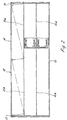
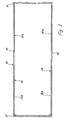
- the structure 10 of a refrigerated vehicle shown purely schematically in FIGS. 1 to 3 consists from the two side walls 11, 12, the associated with the cab of the refrigerator Front wall 13 and a tailgate 14.
- the interior of the structure 10 is shown in the Embodiment by two partitions 15, 16 in three chambers with the same Width divided. In a manner not shown may by one or more refrigeration units the temperatures in the chambers will be different. Thus the unused, empty part
- Each chamber is not acted upon by the cooling air is in each chamber one Sliding element 17 is provided, which according to the figure 6 under the ceiling of the structure can be pivoted to load or unload the chambers, for example or to arrange the partitions 15, 16 on the side walls.
- each partition wall 15, 16 consists of plate-shaped individual wall elements 15a, 15b, 16a and 16b.
- the individual wall elements 15a, 15b, 16a, 16b are in the illustrated embodiment of equal length.
- the perforated rails become commonly referred to as fall.
- the latch can be unlocked to any Single wall element 15a, 15b, 16a, 16b of the normal, the construction in chambers dividing Betnebswolf to move into a non-use position, in which they on the inner surfaces the side walls 11, 12 abut.
- FIG 2 is indicated how the partition wall 15 forming single wall element 15a and 15b to be displaced to the inner surface of the right side wall 11 of the structure 10 to arrive.
- the single wall element 15a is then around the middle Locking swivel. After the back edge on the inner surface of the right Side wall 11 is applied, the release is locked again.
- the single wall element 15a can then be pivoted about this lock, so that it according to the figure 3 to the inner surface of the side wall 11 abuts.
- the front wall 13 is assigned Single wall element 15b pivoted twice in the same way.
- FIG. 2 shows that each individual wall element 15a, 15b, 16a, 16b when pivoting towards the front wall 13 shifts. However, so that no columns to the front wall 13 arise, that of the front wall 13th associated edge region of each partition wall 15, 16 about a vertical axis by an angle swiveling, which is about 90 °.
- FIG. 4 shows the normal operating position shown in FIG. 5 shows the inoperative position of the two partitions 15 shown in FIG. 16 shows.
- a holding profile strip 18 is attached on the front wall 13 associated edges of the single wall elements 15b, 16b .
- this retaining profile strip 18 is articulated or hingedly connected to a rail 19, which corresponds to the representation of the Figure 5 is pivoted by 90 ° when the single wall element 15b, 16b against the side wall 12 is moved.
- a sealing strip 20 insert.
- the sealing strip 20 is a hollow profile strip, which is provided with a mounting foot 20 a, which is the slot of the rail 19 limiting edges behind.
- Side of the sealing strip 20 with two sealing lips 20 b and 20 c is provided, which obliquely to mean symmetry axis of the sealing strip 20 are. This will be in the Betnebs sued the two partitions 15, 16 an optimal sealing effect between the individual chambers reached. If the partitions 15, 16 are driven to the side walls 11, 12, is still one of the sealing lips 20b or 20c on the front wall.
- the sealing strip 20 is made of a flexible material, preferably made of rubber or a rubber-like plastic.
- the retaining profile strip 18 and the rail 19 could be made of a dimensionally stable plastic, be prepared for example by extrusion.
- the hinged or hinge-like Connection could be made by means of a continuous bolt.
- FIG. 6 shows the construction according to FIG. 2 in a side view. This results in, that the single wall elements (15a, 15b, 16a, 16b) in profile rails (21) and in the bottom of the philosophicales are releasably locked.
- the upper profile rails (21) are at a distance from Roof or the upper floor of the expansion, so that the sliding elements (17) in the Space can be folded.
- FIG. 7 shows seven different possibilities in the individual representations 7a to 7g Subdivision of the hold of a refrigerated vehicle.
- the two partitions (15, 16) are pushed against the side walls.
- the sliding elements (17) are at equal distances to the front wall (13), so that a cooling or Freezer and an uncooled room is created.
- the tailgate associated single wall element (16a) is displaced to the side wall.
- the left sliding element (17) is folded under the ceiling, while the middle Sliding element is approximately in the middle of the middle chamber. This will change the volume the left ventricle 50% larger.
- the sliding element (17) of the right chamber is close the tailgate, so that this entire chamber is cooled.
- the individual presentation FIG. 7c shows that also the rear individual element (15a) assigned to the right wall adjoins the associated one Sidewall can be driven so that the sliding elements of the right and the middle chamber in the middle area. This will make the load volume the left Chamber doubles. This loading volume can be further increased by the front, the front wall (13) associated with single wall element (16b) also to the side wall is moved. The sliding element (17) of the middle chamber is then folded up, so that the loading volume of the left chamber is increased by 2.5 times.
- the individual presentation 7e shows that the structure is subdivided into three equal chambers by dividing the partitions (15, 15) 16) in the respective, sharing the structure positions.
- the size of these chambers are determined by the different positions of the sliding elements (17).
- the individual presentation Fig. 7f shows that the left dividing wall (16) travels to the associated side wall was so that the left chamber is twice as large as the right chamber. This Volume can in turn be reduced by the two sliding walls (17).
- the Individual illustration 7g shows a particularly advantageous division of the loading space. Is to a front single element 15b of the partition wall 15 is brought into the normal position.
- the back Partition member 16a of the partition 16 is also in the normal position.
- the at the mutually facing ends of the single wall elements resulting opening is through a sliding element closed.
- the resulting chambers are equal or approximate the same size, due to the offset of the two single wall elements 15b and 16a.
- the Base areas of the two chambers are therefore the same or similar, but by 180 ° turned to each other.
- 7g could also the single wall element 16 b in the normal front position and the rear single wall element 15 a are in the normal rear position.
- the illustrated Positions are to be seen as an example. If necessary, it is also possible that the single wall elements be arranged firmly within the hold, the sliding walls however, should be movable to enlarge or reduce the chambers and to make them accessible.
- the invention is not limited to the illustrated embodiments. It is essential the subdivision of the partitions (15, 16) into single wall elements (15a, 15b, 16a, 16b) and the different sizes of the chambers to be cooled.
Landscapes
- Engineering & Computer Science (AREA)
- Mechanical Engineering (AREA)
- Health & Medical Sciences (AREA)
- Public Health (AREA)
- Thermal Sciences (AREA)
- Transportation (AREA)
- Physics & Mathematics (AREA)
- Refrigerator Housings (AREA)
- Cultivation Of Seaweed (AREA)
- Non-Portable Lighting Devices Or Systems Thereof (AREA)
- Artificial Fish Reefs (AREA)
- Polymers With Sulfur, Phosphorus Or Metals In The Main Chain (AREA)
- Transition And Organic Metals Composition Catalysts For Addition Polymerization (AREA)
Description
- Figur 1
- einen Aufbau eines Kühlfahrzeuges mit zwei Trennwänden in der normalen Betriebsstellung in einem Horizontalschnitt, rein schematisch;
- Figur 2
- eine der Figur 1 entsprechende Darstellung, jedoch die Verfahrbarkeit einer Trennwand darstellend;
- Figur 3
- den Aufbau nach den Figuren 1 und 2, bei der jedoch die beiden Trennwände an die Seitenwände des Aufbaus gebracht sind;
- Figur 4
- das der Vorderwand zugeordnete Ende des Einzelwandelementes in der normalen Betriebsstellung der Zwischenwand und
- Figur 5
- das der Vorderwand des Aufbau zugeordnete Ende eines Einzelwandelementes, wenn sich die Trennwand entsprechend der Figur 3 an der Seitenwand des Aufbaus befindet.
- Figur 6
- eine der Figur 2 entsprechende Seitenansicht
- Figur 7
- sieben verschiedene Möglichkeiten der Unterteilung des Aufbaues eines Kühlfahrzeuges.
Claims (7)
- Kühlfahrzeug mit einem kofferartigen Aufbau, der durch wenigstens eine Trennwand (15, 16) in einzelne Kühlkammern unterteilt ist, wobei jede Trennwand (15, 16) aus wenigstens zwei aneinandergereihten, schwenkbaren Einzelwandelementen (15a, 15b, 16a, 16b) gebildet ist, die in Eckbereichen in Profilschienen (21) verriegelbar, jedoch entriegelbar und schwenkbar gelagert sind, dadurch gekennzeichnet, dass die eine Trennwand (15, 16) bildenden Einzelwandelemente (15a, 15b, 16a, 16b) in Längsrichtung des kofferartigen Aufbaus verlaufen, dass die Eckbereiche jedes Einzelwandelementes (15a, 15b, 16a, 16b) in im Abstand zum Dach des Aufbaus liegende Profilschienen (21) sowie im Boden des Aufbaus derart lösbar verriegelt sind, dass jedes Einzelwandelement (15a, 15b, 16a, 16b) durch Lösen der Verriegelung eines Eckbereiches um die Verriegelung des anderen Eckbereiches vertikal schwenkbar ist.
- Kühlfahrzeug nach Anspruch 1, dadurch gekennzeichnet, dass die vorderen oder hinteren Randbereiche jeder Trennwand (15, 16) als um vertikale Achsen drehbare Schwenkelemente ausgebildet sind, wobei jedes Schwenkelement aus einer Profilschiene (19) gebildet ist, die schwenkbar mit dem zugehörigen Rand eines plattenförmigen Einzelwandelementes (15a, 15b, 16a, 16b) gekoppelt ist.
- Kühlfahrzeug nach Anspruch 2, dadurch gekennzeichnet, dass auf jeden Rand jedes Einzelwandelementes (15a, 15b, 16a, 16b) eine gelenkig mit der Profilschiene (19) gekoppelte Halteprofilleiste (18) aufgesetzt ist.
- Kühlfahrzeug nach Anspruch 2 oder 3, dadurch gekennzeichnet, dass der freie Rand der schwenkbaren Profilschiene (19) einen sich über die gesamte Höhe oder annähernd über die gesamte Höhe erstreckenden, elastischen Dichtstreifen (20) trägt.
- Kühlfahrzeug nach einem oder mehreren der vorhergehenden Ansprüche 1 bis 4, dadurch gekennzeichnet, dass an den oberen, unteren, vorderen und hinteren Rändern sowie in den Stoßbereichen der Einzelwandelemente (15a, 15b, 16a, 16b) elastische Dichtstreifen vorgesehen sind.
- Kühlfahrzeug nach Anspruch 4 oder 5, dadurch gekennzeichnet, dass jeder Dichtstreifen (20) als Hohlprofilstreifen ausgebildet ist und einen Befestigungsfuß (20a) aufweist, der die einen Schlitz in der Profilschiene (19) begrenzenden Randbereich hintergreift.
- Kühlfahrzeug nach Anspruch 5 oder 6, dadurch gekennzeichnet, dass am freien, der schwenkbaren Profilschiene (19) abgewandten Seite des Dichtstreifens (20) wenigstens eine Dichtlippe (20b, 20c) angeformt ist.
Applications Claiming Priority (2)
| Application Number | Priority Date | Filing Date | Title |
|---|---|---|---|
| DE29820764U DE29820764U1 (de) | 1998-11-20 | 1998-11-20 | Kühlfahrzeug |
| DE29820764U | 1998-11-20 |
Publications (2)
| Publication Number | Publication Date |
|---|---|
| EP1002694A1 EP1002694A1 (de) | 2000-05-24 |
| EP1002694B1 true EP1002694B1 (de) | 2005-07-20 |
Family
ID=8065599
Family Applications (1)
| Application Number | Title | Priority Date | Filing Date |
|---|---|---|---|
| EP99122617A Expired - Lifetime EP1002694B1 (de) | 1998-11-20 | 1999-11-13 | Kühlfahrzeug |
Country Status (4)
| Country | Link |
|---|---|
| EP (1) | EP1002694B1 (de) |
| AT (1) | ATE299811T1 (de) |
| DE (2) | DE29820764U1 (de) |
| DK (1) | DK1002694T3 (de) |
Cited By (1)
| Publication number | Priority date | Publication date | Assignee | Title |
|---|---|---|---|---|
| DE202017107732U1 (de) | 2017-12-19 | 2018-01-11 | Werner Brandt | Kofferartiger Aufbau eines Nutzfahrzeugs |
Families Citing this family (8)
| Publication number | Priority date | Publication date | Assignee | Title |
|---|---|---|---|---|
| EP1048519B1 (de) * | 1999-04-28 | 2004-12-15 | Brandt Kühlfahrzeugbau | Kühlfahrzeug |
| DE10010725A1 (de) * | 2000-03-04 | 2001-09-13 | Michaela Bous Trapo Expres Kle | Trennwand für Kühltransporter |
| US6626625B2 (en) | 2000-07-20 | 2003-09-30 | Roger Nelson | System and method for partitioning cargo areas |
| DE20118360U1 (de) * | 2001-10-20 | 2003-02-27 | Körper, Karl-Heinz, 93053 Regensburg | Mobile Kücheneinheit für die Einsatzverpflegung sowie Fahrzeugeinheit mit einer solchen Kücheneinheit |
| DE102005024036A1 (de) | 2005-05-25 | 2006-11-30 | Fahrzeugwerk Bernard Krone Gmbh | Fahrzeugaufbau |
| US8087859B2 (en) | 2008-11-12 | 2012-01-03 | Fg Products, Inc. | Systems and methods for separating cargo spaces |
| US8146985B2 (en) | 2009-07-23 | 2012-04-03 | Fg Products, Inc. | Door seal systems and methods for temperature-controlled cargo containers |
| DE102013110527B4 (de) * | 2013-09-24 | 2017-08-03 | Karosseriewerk Heinrich Meyer Gmbh | Kühlkofferaufbau mit einer teilbaren und verschiebbaren Längstrennwand |
Family Cites Families (10)
| Publication number | Priority date | Publication date | Assignee | Title |
|---|---|---|---|---|
| US2459022A (en) | 1947-08-13 | 1949-01-11 | William W Gentry | Convertible truck body |
| GB772723A (en) * | 1953-09-17 | 1957-04-17 | Percy John Rutty Tapp | Improvements in or relating to vehicles for transporting frozen commodities |
| GB2141769B (en) * | 1983-04-21 | 1986-03-12 | Dover Roller Shutters Ltd | Thermally insulated shutter |
| EP0364198A3 (de) * | 1988-10-11 | 1990-10-31 | York Trailer Company Limited | Kühlfahrzeuge und -container |
| DE9013442U1 (de) | 1990-09-24 | 1991-02-07 | Schmitz-Anhänger Fahrzeugbau-Gesellschaft mbH & Co., 4435 Horstmar | Fahrzeug mit kastenförmigem Laderaum, insbesondere kühlbarem Laderaum, mit einer Trennwand |
| US5161848A (en) * | 1990-11-19 | 1992-11-10 | Kidron, Inc. | Refrigerated vehicle body |
| DE9410286U1 (de) | 1994-06-24 | 1994-08-11 | Helmut Wilke GmbH, 22946 Trittau | Kofferaufbau |
| US5704676A (en) * | 1995-05-22 | 1998-01-06 | Great Dane Limited Partnership | Multi-temperature cargo transportation apparatus |
| DE29604366U1 (de) | 1996-03-09 | 1996-05-09 | Kiesling Fahrzeugbau GmbH, 89160 Dornstadt | Kraftfahrzeug mit einem geschlossenen Fahrzeugaufbau |
| JPH09254704A (ja) * | 1996-03-25 | 1997-09-30 | Nippon Fruehauf Co Ltd | 貨物自動車用荷箱の中仕切装置 |
-
1998
- 1998-11-20 DE DE29820764U patent/DE29820764U1/de not_active Expired - Lifetime
-
1999
- 1999-11-13 EP EP99122617A patent/EP1002694B1/de not_active Expired - Lifetime
- 1999-11-13 AT AT99122617T patent/ATE299811T1/de not_active IP Right Cessation
- 1999-11-13 DE DE59912294T patent/DE59912294D1/de not_active Expired - Lifetime
- 1999-11-13 DK DK99122617T patent/DK1002694T3/da active
Cited By (1)
| Publication number | Priority date | Publication date | Assignee | Title |
|---|---|---|---|---|
| DE202017107732U1 (de) | 2017-12-19 | 2018-01-11 | Werner Brandt | Kofferartiger Aufbau eines Nutzfahrzeugs |
Also Published As
| Publication number | Publication date |
|---|---|
| EP1002694A1 (de) | 2000-05-24 |
| DE59912294D1 (de) | 2005-08-25 |
| DK1002694T3 (da) | 2005-11-21 |
| ATE299811T1 (de) | 2005-08-15 |
| DE29820764U1 (de) | 1999-01-14 |
Similar Documents
| Publication | Publication Date | Title |
|---|---|---|
| WO2004104504A1 (de) | Auszugkasten für ein kältegerät | |
| EP2118595A1 (de) | Butterfach für ein kältegerät | |
| DE19837685A1 (de) | Laderaum für ein Kraftfahrzeug und Segmentierungsvorrichtung | |
| DE60129142T2 (de) | Fahrzeug | |
| WO2021198073A1 (de) | Fahrzeugbereich mit gepäckfach und deckenpaneel oberhalb des gepäckfaches, und verfahren zum einbau und ausbau eines deckenpaneels oberhalb eines gepäckfaches | |
| DE69109486T2 (de) | Vorrichtung an runger für ladeplattformen an fahrzeugen mit abdeckung und abdeckungshalter. | |
| EP1002694A1 (de) | Kühlfahrzeug | |
| DE69815798T2 (de) | Vorgefertigter transportierbarer modularer Schutzraum | |
| DE2329016A1 (de) | Moebel, das aus mehreren gleichen elementen zusammengesetzt ist, insbesondere moebel aus kunststoff | |
| EP1048519B1 (de) | Kühlfahrzeug | |
| DE3805525A1 (de) | Fahrzeug zum transport und zur verteilung von guetern im frischdienst und/oder tiefkuehldienst | |
| EP2924214B1 (de) | Frontelement | |
| DE102006018179B4 (de) | Aufbau für ein Fahrzeug | |
| EP1984686A2 (de) | Kältegerät und fachboden dafür | |
| DE19962825A1 (de) | Abtrennung für geschlossene LKW-Aufbauten | |
| DE2507627A1 (de) | Behaelter | |
| EP2524857A1 (de) | System mit Einzelmodulen zur Bildung eines Kofferaufbaus | |
| EP1389562B1 (de) | Vorrichtung zum Sichern von Ladegut auf der Ladefläche eines Fahrzeuges | |
| EP4570545A1 (de) | Nutzfahrzeugaufbau mit rolltor | |
| CH661853A5 (de) | Moebel. | |
| EP1462286A2 (de) | Aufbau für einen Lastkraftwagen oder einen Anhänger für Lastkraftwagen | |
| DE29604366U1 (de) | Kraftfahrzeug mit einem geschlossenen Fahrzeugaufbau | |
| EP4570546A1 (de) | Nutzfahrzeugaufbau und nutzfahrzeug mit rolltor | |
| DE102013110527B4 (de) | Kühlkofferaufbau mit einer teilbaren und verschiebbaren Längstrennwand | |
| EP1714815B1 (de) | Fahrzeugrolltor |
Legal Events
| Date | Code | Title | Description |
|---|---|---|---|
| PUAI | Public reference made under article 153(3) epc to a published international application that has entered the european phase |
Free format text: ORIGINAL CODE: 0009012 |
|
| AK | Designated contracting states |
Kind code of ref document: A1 Designated state(s): AT BE CH CY DE DK ES FI FR GB GR IE IT LI LU MC NL PT SE |
|
| AX | Request for extension of the european patent |
Free format text: AL;LT;LV;MK;RO;SI |
|
| 17P | Request for examination filed |
Effective date: 20000705 |
|
| AKX | Designation fees paid |
Free format text: AT BE CH CY DE DK ES FI FR GB GR IE IT LI LU MC NL PT SE |
|
| GRAP | Despatch of communication of intention to grant a patent |
Free format text: ORIGINAL CODE: EPIDOSNIGR1 |
|
| GRAS | Grant fee paid |
Free format text: ORIGINAL CODE: EPIDOSNIGR3 |
|
| GRAA | (expected) grant |
Free format text: ORIGINAL CODE: 0009210 |
|
| AK | Designated contracting states |
Kind code of ref document: B1 Designated state(s): AT BE CH CY DE DK ES FI FR GB GR IE IT LI LU MC NL PT SE |
|
| PG25 | Lapsed in a contracting state [announced via postgrant information from national office to epo] |
Ref country code: FI Free format text: LAPSE BECAUSE OF FAILURE TO SUBMIT A TRANSLATION OF THE DESCRIPTION OR TO PAY THE FEE WITHIN THE PRESCRIBED TIME-LIMIT Effective date: 20050720 Ref country code: ES Free format text: LAPSE BECAUSE OF FAILURE TO SUBMIT A TRANSLATION OF THE DESCRIPTION OR TO PAY THE FEE WITHIN THE PRESCRIBED TIME-LIMIT Effective date: 20050720 |
|
| REG | Reference to a national code |
Ref country code: GB Ref legal event code: FG4D Free format text: NOT ENGLISH |
|
| REG | Reference to a national code |
Ref country code: CH Ref legal event code: EP |
|
| REG | Reference to a national code |
Ref country code: IE Ref legal event code: FG4D Free format text: LANGUAGE OF EP DOCUMENT: GERMAN |
|
| REF | Corresponds to: |
Ref document number: 59912294 Country of ref document: DE Date of ref document: 20050825 Kind code of ref document: P |
|
| GBT | Gb: translation of ep patent filed (gb section 77(6)(a)/1977) |
Effective date: 20050908 |
|
| PG25 | Lapsed in a contracting state [announced via postgrant information from national office to epo] |
Ref country code: SE Free format text: LAPSE BECAUSE OF FAILURE TO SUBMIT A TRANSLATION OF THE DESCRIPTION OR TO PAY THE FEE WITHIN THE PRESCRIBED TIME-LIMIT Effective date: 20051020 Ref country code: GR Free format text: LAPSE BECAUSE OF FAILURE TO SUBMIT A TRANSLATION OF THE DESCRIPTION OR TO PAY THE FEE WITHIN THE PRESCRIBED TIME-LIMIT Effective date: 20051020 |
|
| REG | Reference to a national code |
Ref country code: GB Ref legal event code: 732E |
|
| PG25 | Lapsed in a contracting state [announced via postgrant information from national office to epo] |
Ref country code: IT Free format text: LAPSE BECAUSE OF NON-PAYMENT OF DUE FEES Effective date: 20051113 Ref country code: CY Free format text: LAPSE BECAUSE OF FAILURE TO SUBMIT A TRANSLATION OF THE DESCRIPTION OR TO PAY THE FEE WITHIN THE PRESCRIBED TIME-LIMIT Effective date: 20051113 Ref country code: AT Free format text: LAPSE BECAUSE OF NON-PAYMENT OF DUE FEES Effective date: 20051113 |
|
| REG | Reference to a national code |
Ref country code: DK Ref legal event code: T3 |
|
| PG25 | Lapsed in a contracting state [announced via postgrant information from national office to epo] |
Ref country code: MC Free format text: LAPSE BECAUSE OF NON-PAYMENT OF DUE FEES Effective date: 20051130 Ref country code: LU Free format text: LAPSE BECAUSE OF NON-PAYMENT OF DUE FEES Effective date: 20051130 Ref country code: LI Free format text: LAPSE BECAUSE OF NON-PAYMENT OF DUE FEES Effective date: 20051130 Ref country code: CH Free format text: LAPSE BECAUSE OF NON-PAYMENT OF DUE FEES Effective date: 20051130 Ref country code: BE Free format text: LAPSE BECAUSE OF NON-PAYMENT OF DUE FEES Effective date: 20051130 |
|
| PG25 | Lapsed in a contracting state [announced via postgrant information from national office to epo] |
Ref country code: PT Free format text: LAPSE BECAUSE OF FAILURE TO SUBMIT A TRANSLATION OF THE DESCRIPTION OR TO PAY THE FEE WITHIN THE PRESCRIBED TIME-LIMIT Effective date: 20051221 |
|
| ET | Fr: translation filed | ||
| PLBE | No opposition filed within time limit |
Free format text: ORIGINAL CODE: 0009261 |
|
| STAA | Information on the status of an ep patent application or granted ep patent |
Free format text: STATUS: NO OPPOSITION FILED WITHIN TIME LIMIT |
|
| 26N | No opposition filed |
Effective date: 20060421 |
|
| REG | Reference to a national code |
Ref country code: CH Ref legal event code: PL |
|
| NLT1 | Nl: modifications of names registered in virtue of documents presented to the patent office pursuant to art. 16 a, paragraph 1 |
Owner name: BRANDT-KUEHLFAHRZEUGBAU GMBH & CO. KG |
|
| REG | Reference to a national code |
Ref country code: FR Ref legal event code: CD |
|
| BERE | Be: lapsed |
Owner name: BRANDT KUHLFAHRZEUGBAU Effective date: 20051130 |
|
| PGRI | Patent reinstated in contracting state [announced from national office to epo] |
Ref country code: IT Effective date: 20091201 |
|
| PGFP | Annual fee paid to national office [announced via postgrant information from national office to epo] |
Ref country code: DK Payment date: 20141124 Year of fee payment: 16 |
|
| PGFP | Annual fee paid to national office [announced via postgrant information from national office to epo] |
Ref country code: DE Payment date: 20141201 Year of fee payment: 16 |
|
| PGFP | Annual fee paid to national office [announced via postgrant information from national office to epo] |
Ref country code: NL Payment date: 20141120 Year of fee payment: 16 Ref country code: FR Payment date: 20141118 Year of fee payment: 16 |
|
| PGFP | Annual fee paid to national office [announced via postgrant information from national office to epo] |
Ref country code: IT Payment date: 20141121 Year of fee payment: 16 |
|
| REG | Reference to a national code |
Ref country code: DE Ref legal event code: R119 Ref document number: 59912294 Country of ref document: DE |
|
| REG | Reference to a national code |
Ref country code: DK Ref legal event code: EBP Effective date: 20151130 |
|
| PG25 | Lapsed in a contracting state [announced via postgrant information from national office to epo] |
Ref country code: IT Free format text: LAPSE BECAUSE OF NON-PAYMENT OF DUE FEES Effective date: 20151113 |
|
| REG | Reference to a national code |
Ref country code: NL Ref legal event code: MM Effective date: 20151201 |
|
| REG | Reference to a national code |
Ref country code: FR Ref legal event code: ST Effective date: 20160729 |
|
| PG25 | Lapsed in a contracting state [announced via postgrant information from national office to epo] |
Ref country code: NL Free format text: LAPSE BECAUSE OF NON-PAYMENT OF DUE FEES Effective date: 20151201 |
|
| PG25 | Lapsed in a contracting state [announced via postgrant information from national office to epo] |
Ref country code: DE Free format text: LAPSE BECAUSE OF NON-PAYMENT OF DUE FEES Effective date: 20160601 Ref country code: DK Free format text: LAPSE BECAUSE OF NON-PAYMENT OF DUE FEES Effective date: 20151130 |
|
| PG25 | Lapsed in a contracting state [announced via postgrant information from national office to epo] |
Ref country code: FR Free format text: LAPSE BECAUSE OF NON-PAYMENT OF DUE FEES Effective date: 20151130 |
|
| PGFP | Annual fee paid to national office [announced via postgrant information from national office to epo] |
Ref country code: IE Payment date: 20181121 Year of fee payment: 20 |
|
| PGFP | Annual fee paid to national office [announced via postgrant information from national office to epo] |
Ref country code: GB Payment date: 20181126 Year of fee payment: 20 |
|
| REG | Reference to a national code |
Ref country code: GB Ref legal event code: PE20 Expiry date: 20191112 |
|
| REG | Reference to a national code |
Ref country code: IE Ref legal event code: MK9A |
|
| PG25 | Lapsed in a contracting state [announced via postgrant information from national office to epo] |
Ref country code: IE Free format text: LAPSE BECAUSE OF EXPIRATION OF PROTECTION Effective date: 20191113 Ref country code: GB Free format text: LAPSE BECAUSE OF EXPIRATION OF PROTECTION Effective date: 20191112 |