EP1000727B1 - Method and apparatus for detecting pressure in a compression mould - Google Patents
Method and apparatus for detecting pressure in a compression mould Download PDFInfo
- Publication number
- EP1000727B1 EP1000727B1 EP99309105A EP99309105A EP1000727B1 EP 1000727 B1 EP1000727 B1 EP 1000727B1 EP 99309105 A EP99309105 A EP 99309105A EP 99309105 A EP99309105 A EP 99309105A EP 1000727 B1 EP1000727 B1 EP 1000727B1
- Authority
- EP
- European Patent Office
- Prior art keywords
- workpiece
- mold
- touch
- mold closure
- touch sensor
- Prior art date
- Legal status (The legal status is an assumption and is not a legal conclusion. Google has not performed a legal analysis and makes no representation as to the accuracy of the status listed.)
- Expired - Lifetime
Links
- 230000006835 compression Effects 0.000 title claims description 24
- 238000007906 compression Methods 0.000 title claims description 24
- 238000000034 method Methods 0.000 title claims description 17
- 238000000748 compression moulding Methods 0.000 claims description 19
- 230000033001 locomotion Effects 0.000 claims description 9
- 230000002708 enhancing effect Effects 0.000 claims description 4
- 229920005989 resin Polymers 0.000 claims description 3
- 239000011347 resin Substances 0.000 claims description 3
- 229920002379 silicone rubber Polymers 0.000 claims description 3
- 239000004945 silicone rubber Substances 0.000 claims description 3
- 229920005992 thermoplastic resin Polymers 0.000 claims description 2
- 239000000463 material Substances 0.000 description 9
- 239000010410 layer Substances 0.000 description 7
- 239000002184 metal Substances 0.000 description 7
- 238000000465 moulding Methods 0.000 description 5
- 239000000835 fiber Substances 0.000 description 4
- 238000005259 measurement Methods 0.000 description 4
- 238000010586 diagram Methods 0.000 description 3
- 230000011664 signaling Effects 0.000 description 3
- 230000037303 wrinkles Effects 0.000 description 3
- OAICVXFJPJFONN-UHFFFAOYSA-N Phosphorus Chemical compound [P] OAICVXFJPJFONN-UHFFFAOYSA-N 0.000 description 2
- 238000004891 communication Methods 0.000 description 2
- 238000000280 densification Methods 0.000 description 2
- 239000000758 substrate Substances 0.000 description 2
- 229920000049 Carbon (fiber) Polymers 0.000 description 1
- 229920000271 Kevlar® Polymers 0.000 description 1
- 229920004142 LEXAN™ Polymers 0.000 description 1
- 239000004418 Lexan Substances 0.000 description 1
- 239000004697 Polyetherimide Substances 0.000 description 1
- 230000005856 abnormality Effects 0.000 description 1
- 238000005452 bending Methods 0.000 description 1
- 239000004917 carbon fiber Substances 0.000 description 1
- 239000011247 coating layer Substances 0.000 description 1
- 239000004020 conductor Substances 0.000 description 1
- 230000001419 dependent effect Effects 0.000 description 1
- 230000000694 effects Effects 0.000 description 1
- 239000003822 epoxy resin Substances 0.000 description 1
- 238000010438 heat treatment Methods 0.000 description 1
- 239000012212 insulator Substances 0.000 description 1
- 239000004761 kevlar Substances 0.000 description 1
- 238000004519 manufacturing process Methods 0.000 description 1
- 239000012528 membrane Substances 0.000 description 1
- VNWKTOKETHGBQD-UHFFFAOYSA-N methane Chemical compound C VNWKTOKETHGBQD-UHFFFAOYSA-N 0.000 description 1
- 239000004417 polycarbonate Substances 0.000 description 1
- 229920000515 polycarbonate Polymers 0.000 description 1
- 229920000647 polyepoxide Polymers 0.000 description 1
- 229920001601 polyetherimide Polymers 0.000 description 1
Images

Classifications
-
- B—PERFORMING OPERATIONS; TRANSPORTING
- B29—WORKING OF PLASTICS; WORKING OF SUBSTANCES IN A PLASTIC STATE IN GENERAL
- B29C—SHAPING OR JOINING OF PLASTICS; SHAPING OF MATERIAL IN A PLASTIC STATE, NOT OTHERWISE PROVIDED FOR; AFTER-TREATMENT OF THE SHAPED PRODUCTS, e.g. REPAIRING
- B29C43/00—Compression moulding, i.e. applying external pressure to flow the moulding material; Apparatus therefor
- B29C43/32—Component parts, details or accessories; Auxiliary operations
- B29C43/58—Measuring, controlling or regulating
Definitions
- This invention relates to a touch sensor, and more specifically, to enhancing contact or pressure between a mold closure and a workpiece to prevent lateral movement of the workpiece during compression molding.
- a multilayered workpiece is formed layer by layer, where individual layers can vary by at least 5-10% in thickness.
- the workpiece is then debulked by applying a vacuum and heat to remove gas and pre-densify the workpiece. Finally, the workpiece is placed in a sealed bag in a mold and further densified into a final formed workpiece using only autoclave air pressure. Compression molding a debulked workpiece, however, has been found to provide better exterior surface geometry than conventional autoclave molding, as well as forcing the workpiece to a final geometry which is less dependent on material layer variability.
- the preformed workpiece is assembled similar to the autoclave process. Instead of autoclave molding the workpiece for final densification, however, the debulked workpiece is placed in a compression mold cavity and a mold closure moves into contact with the workpiece while the mold is also heated according to a pre-determined temperature schedule. Final densification of the workpiece is performed by compressing the workpiece between the mold cavity and the mold closure within the mold.
- the act of obtaining better exterior surface geometry through compression molding may, in some cases, lead to the generation of excessive lateral flow of one or more layers of the workpiece.
- the excessive lateral flow may tend to form wrinkles in the one or more layers.
- wrinkles create an abnormality in the workpiece and in some cases may lead to a derating of the strength of the final formed workpiece.
- One cause for the excessive lateral flow is believed to be non-uniform contact between the mold and the workpiece, particularly upon initial contact of the mold with the workpiece before compression molding commences.
- Another cause is believed to be non-uniform pressure applied to the workpiece during compression molding. Consequently, it is desirable to assure that the mold contacts the preformed workpiece as completely and uniformly as possible before and during compression molding to reduce the likelihood of excessive lateral motion of the workpiece relative to the mold. For a similar reason, it is desirable to assure that the pressure applied upon the preformed workpiece during compression molding is tailored to get a high quality part.
- an apparatus for sensing touch between a compression mold and a workpiece located in said compression mold including a mold cavity and a mold closure movable relative to said workpiece, characterized by:at least one compliant sensor sheet positionable to signal touch between said mold closure and said workpiece; wherein at least one touch sensor comprises a plurality of touch sensor pads disposed to signal touch between said mold closure and said workpiece at a plurality of different points across a surface of said workpiece to generate a signal that indicates when said mold closure contacts a portion of said workpiece and controls the mold closure based on said signal to contact said workpiece with said remaining portion of said mold closure.
- a method for sensing touch between a compression mold and a workpiece located in said compression mold including a mold cavity and a mold closure movable relative to said workpiece, characterized by positioning at least one compliant
- sensor sheet including at least one contact touch sensor pad to indicated touch between said mold closure and said workpiece; generating a signal indicating touch between said mold closure and said workpiece, the signal indicating at least contact therebewteen and; removing said workpiece from said mold: and separating said sensor sheet (18) from said workpiece.
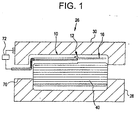
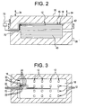
- FIGS. 1-3 diagrammatically illustrate an apparatus 10 for sensing touch between a mold 26, for example, a compression mold, and a workpiece 40, typically composed of multiple layers of material.
- Mold 26 may comprise any conventional compression molding machine that includes a compression mold closure 30, a compression mold cavity 28 and a mold aperture 70 leading from inside mold cavity 28 to an outside environment.
- mold 26 comprises a four-piston hydraulic type of compression mold machine, for example, a MurdockTM compression mold machine.
- Workpiece 40 can be positioned in mold cavity 28, which mold cavity 28 is preferably substantially fixed relative to workpiece 40, and thereby workpiece 40 is movable relative to mold closure 30.
- At least one touch sensor such as touch sensor pad 12, is positionable to signal how mold closure 30 touches workpiece 40.
- touch is used herein to include any force or effect from mold 26 on workpiece 40 or vice versa.
- Such touch could range from direct physical touch between opposing surfaces of each to touch between opposing surfaces of each via at least one intermediary means.
- touch could range from mere contact, as contact is defined herein, to pressure, as pressure is defined herein, between opposing surfaces of workpiece 40 and mold 26.
- touch sensor 12 typically comprises at least a contact sensor, such as a contact type touch sensor pad 14.
- Pad 14 can generate a signal that indicates when compression mold closures 30 contacts workpiece 40 as mold closure 30 is moved into position towards workpiece 40 and mold cavity 28 (FIG. 2).
- the term contact is used herein to include any contact between mold closure 30 and workpiece 40 ranging from direct physical contact between opposing surfaces of each to contact between opposing surfaces of each via at least one intermediary means.
- contact can be indicated at any time with this invention, it is most useful to know when initial contact is made between mold closure 30 and workpiece 40. For example, the time of this initial contact can be usefully employed as "time-zero" to begin a two step controlled process of (1) closing mold 26 and (2) starting the mold heating.
- Each step preferably has its own baseline schedule of closure (or preferred force exerted upon workpiece 40) and heat applications, respectively, from then on through completion of the molding process. Subsequent contacts across the surface of workpiece 40, however, can also be used to modify these baseline schedules during the molding process.
- touch sensor 12 may comprise a pressure sensor, such as a pressure type touch sensor pad 84.
- the pressure sensor can provide a signal that indicates a surface pressure between workpiece 40 and compression mold closure 30 adjacent sensor 12, for example, local surface pressure.
- the term pressure is used herein to include any pressure between mold closure 30 and workpiece 40 ranging from direct physical pressure between opposing surfaces of each to pressure between opposing surfaces of each via at least one intermediary means. Although pressure can be indicated at any time with this invention, it is most useful to know what the local workpiece surface pressure is throughout compression molding after initial contact between the mold closure and the workpiece.
- At least one sensor 12 preferably comprises a plurality of sensors 12 disposed to signal touch between mold closure 30 and workpiece 40 at a plurality of different points across a surface 42 of workpiece 40.
- each sensor 12 may include a contact sensor or pressure sensor, or both.
- mold closure 30 tilt relative to workpiece 40 to increase a total number of the plurality of different points signaling touch between mold closure 30 and workpiece 40. Tilting may be achieved through manipulation of mold closure 30 by manual or automatic means. Preferably, tilting is enabled in opposing directions 34 along at least one diameter of mold 26 and most preferably along multiple diameters of mold 26.
- FIG. 4 schematically depicts compression mold 26, a compression mold control system 36 and a touch sensor monitor 38. Each communicate with one another to operate mold 26 and monitor and interpret how mold closure 30 is in touch with workpiece 40. For example, manual or automatic means may be utilized to monitor touch between workpiece 40 and mold closure 30 and also to interpret the signal towards controlling movement of mold closure 30 based on the interpreted signal.
- FIG. 5 diagrammatically illustrates contact type touch sensor pad 14, which pad 14 is positionable between mold closure 30 and workpiece 40.
- Contact type touch sensor pad 14 may comprise a touch sensor assembly 16 including a compliant sheet material 18 and contact type touch sensor pad 14.
- contact type touch sensor pad 14 comprises a membrane switch used, for example, in appliance user interfaces.
- Such a low pressure sensor pad e.g., preferably ⁇ 6895 pascals (1 psi)
- compliant sheet 18 comprises a nonconductive deformable member from the group consisting of resin, thermoplastic resin and silicone rubber, such as GE Lexan TM polycarbonate, GE Ultrin TM polyetherimide or DuPont Kevlar TM resins.
- each contact type touch sensor pad 14 may be connected to a signal run 20 to provide communication from pad 14 to outside of mold 26.
- metal contact type touch sensor pads 14 and metal signal runs (e.g., wires) 20 may be utilized for signaling contact with a metal mold closure 30.
- at least one conventional touch sensor monitor for example, an Ohm meter 72 (FIG. 2), may be connected to signal runs 20 outside of mold 26.
- This may include use of a wire connector junction 22 (FIG. 3)or signal runs 20 may extend continuously uninterrupted from pads 14 to outside of mold 26.
- signal runs 20 exit mold interior through mold aperture 70, or the like, including any of several conventional seal structures such as elastomeric seals or fast cure seals that can be broken off signal runs 20 when compression molding is completed.
- pads 14 signal contact at one or more points across surface 42 of workpiece 40. That is, signal runs 20 may be sequentially connected to a low, DC voltage source whose other terminal would be connected to metal mold closure 30.
- contact type touch sensor pad 14 closes the circuit in a simple continuity check arrangement. This information could be interpreted, by conventional means, to determine which contact type touch sensor pad(s) 14 contact mold closure 30. This information may in turn thereby provide direction to a manual operator or automatic control system as to how to tilt mold closure 30 to enhance a touch result, for example, contact, between mold closure 30 and workpiece 40.
- FIG. 6 diagrammatically illustrates an alternative embodiment of a contact type touch sensor pad 76 and touch sensor assembly 16 of this invention.
- the sensor can be completely encapsulated within compliant sheet material 18.
- Contact type touch sensor pad 76 can be formed by two opposing surfaces of signal run 20 (for example, a wire) spaced from each other by an insulator 24.
- Such a contact type touch sensor pad 76 may further include a pair of nubs 56 wherein outside pressure applied to nubs 56 presses them inward toward each other and when their opposing surfaces contact, a circuit is completed, including wire run 20.
- this embodiment need not be compatible with mold closure 30 (i.e., metal to metal, etc.) because contact type touch sensor pad 76 is wholly contained within compliant sheet material 18.
- this embodiment may merely depend on signal communication through contact type touch sensor pad 76 and signal run 20.
- this embodiment is similar to contact type touch sensor pad 14.
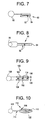
- FIG. 7 diagrammatically illustrates a strain gauge pressure type touch sensor which is positionable between mold closure 30 and workpiece 40.
- This pressure type touch sensor may also comprise touch sensor assembly 16 including compliant sheet material 18 and a pressure type touch sensor pad 80 or contact type touch sensor pad(s) 14 or 76, and preferably both.
- Such a pressure sensor e.g., preferably sensitive at 10psi to 1000psi), more accurately measures local surface pressure between workpiece 40 and mold closure 30 throughout compression molding of workpiece 40.
- Touch sensor of this invention may comprise a single structure having the features and pressure ranges desired for both contact type and pressure type touch sensors of the invention.
- the pressure type touch sensor comprises a flat strain gauge pad 80.
- Pad 80 may include a resistor 82 mounted on a deflectable bar or disc substrate 84.
- bending substrate 84 changes the resistance measured by a resistance monitor 86, and this measurement can be used to determine pressure differentials.
- FIG. 8 diagrammatically illustrates another embodiment of a pressure type touch sensor pad 90, which, aside from its particular function, is interchangeable with the strain gauge type sensor (FIG. 7).
- Sensor pad 90 may comprise a piezoelectric sensor pad.
- the sensor may include electrodes 92 plated on piezoelectric material 94. In use, changes in external pressure change the voltage measured by a conventional voltage monitor 96, and this measurement can be used to determine pressure differentials.
- FIG. 9 diagrammatically illustrates another embodiment of a pressure type touch sensor pad which, aside from its particular function, is interchangeable - with the strain gauge type sensor (FIG. 7).
- Sensor pad 100 illustrates a conventional capacitive sensor pad.
- the sensor may include deformable material 104 between stiff conductors 102.
- a gap 106-106 reduces under loading and system capacitance increases, as measured by a capacitance monitor 108, and this measurement can be used to determine pressure differentials.
- FIG. 10 diagrammatically illustrates another embodiment of a pressure type touch sensor pad 110 which, aside from its particular function, is interchangeable with the strain gauge type sensor (FIG. 7).
- Sensor pad 110 illustrates a fiber optic sensor pad.
- the sensor may include a fiber optic sensor 114, with a phosphor coated tip 120, surrounded by a gel 112 (e.g., silicone rubber) in a pressure-tight elastomeric bag 116.
- a gel 112 e.g., silicone rubber
- a monitor 118 e.g., silicone rubber
- This measurement can be used to determine pressure differentials.
- a Ruxtron Co.TM or Panametrics Co.TTM fiber optic pressure type touch sensor pad is contemplated to produce excellent results.
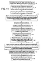
- FIG. 11 depicts a flow diagram for practicing the invention.
- at least one touch sensor 12 and preferably a plurality of contact type and pressure type touch sensors, are positioned adjacent to workpiece 40 or mold closure 30, at step 44.
- mold closure 30 and workpiece 40 are moved, preferably slowly, relative to one another (either or both moving, but preferably only mold closure 30 moving) and a signal is generated indicating how mold closure 30 touches workpiece 40, at step 46.
- the signal may comprise a single signal or multiple signals, either or both being associated with a single touch sensor 12 or multiple touch sensors 12 depending on the intended use.
- the step 46 signal is then interpreted to produce an interpreted signal, by conventional means that may be manual or automatic as discussed above, at step 48.
- the movement of mold closure 30 is conventionally guided, manually or automatically as discussed above, by changing a rate of closure or tilting the same.
- the interpreted signal and guided movement are utilized towards enhancing a touch result between workpiece 40 and mold closure 30, for example, such as increasing the total number of the plurality of different points signaling contact between mold closure 30 and workpiece 40, at step 52.
- workpiece 40 may then be compression molded, at step 54.
- this may include substantially preventing lateral movement of workpiece 40, namely the individual layers or material thereof, during compression molding.
- This may also include modifying the temperature of workpiece 40, by conventional means, according to a desired temperature schedule as discussed previously, at step 74.
- the signal from step 46, or a second signal generated from touch sensor 12 may indicate a local surface pressure between workpiece 12 and mold closure 30, at step 56, which may also depend on the temperature of workpiece 40.
- the signal or second signal is then interpreted to produce a second interpreted signal, by conventional means that may be manual or automatic as discussed above, at step 58.
- the movement of mold closure 30 is further conventionally guided, manually or automatically as discussed above, by further changing the rate of closure or tilting the same as done previously, at step 60.
- compression molding comprises compression molding workpiece 40 into a high quality part as a result of the enhanced touch results between workpiece 40 and mold closure 30, i.e., substantially no wrinkles, substantially full density, substantially no porosity and preferred geometric specifications, at step 62.
- the touch result desired e.g., maximizing contact between workpiece 40 and mold closure 30 or maintaining a desired pressure at the surface of workpiece 40 in spite of thermal expansion during molding, can be obtained.
- the uniform structural integrity of the surface of workpiece 40 opposing mold closure 30 is maintained during the whole process such that any touch upon workpiece 40 by touch sensor(s) 12 is negligible to the final formed workpiece, at step 64.
- this may be achieved by conventional means for maintaining a uniform thickness to the touch sensor assembly 16 in an environment ranging from mere atmospheric pressure to the high pressures experienced during compression molding.
- mold closure 30 may have recesses (not shown) to receive the contact sensor pads 14 and otherwise may also maintain a uniform thickness to touch sensor assembly 16 similar to the embodiment of FIG. 6.
- touch sensor(s) 12 or touch sensor assembly 16 is separated from at least workpiece 40, at step-68.
- contact sensor(s) 14 may also be separated from mold closure 30.
- touch sensor(s) 12, or the touch sensor assembly 16 is reusable from one workpiece to another, and most preferably from one mold 26 to another.
- This invention may have an endless variety of uses for all kinds of compression molded devices. Presently though, excellent results are contemplated when the invention is used to manufacture aircraft engine fan blades made of laminated sheets of epoxy resin reinforced by unidirectional carbon fiber tows.
Landscapes
- Engineering & Computer Science (AREA)
- Mechanical Engineering (AREA)
- Casting Or Compression Moulding Of Plastics Or The Like (AREA)
- Mounting, Exchange, And Manufacturing Of Dies (AREA)
- Measurement Of Force In General (AREA)
- Force Measurement Appropriate To Specific Purposes (AREA)
- Moulds For Moulding Plastics Or The Like (AREA)
Applications Claiming Priority (2)
| Application Number | Priority Date | Filing Date | Title |
|---|---|---|---|
| US192427 | 1980-09-29 | ||
| US09/192,427 US6294113B1 (en) | 1998-11-16 | 1998-11-16 | Touch sensing method |
Publications (2)
| Publication Number | Publication Date |
|---|---|
| EP1000727A1 EP1000727A1 (en) | 2000-05-17 |
| EP1000727B1 true EP1000727B1 (en) | 2006-02-01 |
Family
ID=22709603
Family Applications (1)
| Application Number | Title | Priority Date | Filing Date |
|---|---|---|---|
| EP99309105A Expired - Lifetime EP1000727B1 (en) | 1998-11-16 | 1999-11-16 | Method and apparatus for detecting pressure in a compression mould |
Country Status (4)
| Country | Link |
|---|---|
| US (2) | US6294113B1 (enExample) |
| EP (1) | EP1000727B1 (enExample) |
| JP (1) | JP4588145B2 (enExample) |
| DE (1) | DE69929663T2 (enExample) |
Families Citing this family (22)
| Publication number | Priority date | Publication date | Assignee | Title |
|---|---|---|---|---|
| US6294113B1 (en) * | 1998-11-16 | 2001-09-25 | General Electric Company | Touch sensing method |
| US20030075936A1 (en) * | 2001-10-19 | 2003-04-24 | Taiwan Semiconductor Manufacturing Co., Ltd. | Wafer blade equipped with piezoelectric sensors |
| US6756703B2 (en) * | 2002-02-27 | 2004-06-29 | Chi Che Chang | Trigger switch module |
| US7014453B2 (en) | 2002-12-17 | 2006-03-21 | Lear Corporation | Machine having sensors for controlling molding operation |
| TW587008B (en) * | 2003-01-20 | 2004-05-11 | Asia Optical Co Inc | Pressure regulating device for injection molding mold unit |
| WO2004112448A2 (en) * | 2003-06-13 | 2004-12-23 | Semtech Corporation | Sensor for capacitive touch pad pointing device |
| TWI226934B (en) * | 2003-11-27 | 2005-01-21 | Hong Hocheng | System of nanoimprint with mold deformation detector and method of monitoring the same |
| US20050236725A1 (en) * | 2004-04-23 | 2005-10-27 | Niewels Joachim J | Method and apparatus for countering mold deflection and misalignment using active material elements |
| US7072533B1 (en) * | 2005-09-26 | 2006-07-04 | Visteon Global Technologies, Inc. | Automotive optical touch sensitive switch method |
| US20110147973A1 (en) * | 2009-12-17 | 2011-06-23 | Kuo-Hua Sung | Injection Molding of Touch Surface |
| US9656434B2 (en) | 2010-11-30 | 2017-05-23 | The Good Year Tire & Rubber Company | Measuring tire pressure in a tire mold |
| US10677259B2 (en) | 2016-05-06 | 2020-06-09 | General Electric Company | Apparatus and system for composite fan blade with fused metal lead edge |
| US10760428B2 (en) | 2018-10-16 | 2020-09-01 | General Electric Company | Frangible gas turbine engine airfoil |
| US10837286B2 (en) | 2018-10-16 | 2020-11-17 | General Electric Company | Frangible gas turbine engine airfoil with chord reduction |
| US11111815B2 (en) | 2018-10-16 | 2021-09-07 | General Electric Company | Frangible gas turbine engine airfoil with fusion cavities |
| US11434781B2 (en) | 2018-10-16 | 2022-09-06 | General Electric Company | Frangible gas turbine engine airfoil including an internal cavity |
| US11149558B2 (en) | 2018-10-16 | 2021-10-19 | General Electric Company | Frangible gas turbine engine airfoil with layup change |
| US10746045B2 (en) | 2018-10-16 | 2020-08-18 | General Electric Company | Frangible gas turbine engine airfoil including a retaining member |
| EP4071450B1 (en) * | 2021-04-07 | 2024-02-28 | TE Connectivity Solutions GmbH | Load cell with a force transmitting element held by a gel element |
| US12116903B2 (en) | 2021-06-30 | 2024-10-15 | General Electric Company | Composite airfoils with frangible tips |
| US11674399B2 (en) | 2021-07-07 | 2023-06-13 | General Electric Company | Airfoil arrangement for a gas turbine engine utilizing a shape memory alloy |
| US11668317B2 (en) | 2021-07-09 | 2023-06-06 | General Electric Company | Airfoil arrangement for a gas turbine engine utilizing a shape memory alloy |
Family Cites Families (15)
| Publication number | Priority date | Publication date | Assignee | Title |
|---|---|---|---|---|
| DE2950441C2 (de) * | 1979-12-14 | 1986-04-10 | Bison-Werke Bähre & Greten GmbH & Co KG, 3257 Springe | Auf Zylinder-Kolbenanordnungen einwirkende Meß- und Steuereinrichtung an einer Heizplattenpresse zur Herstellung von Werkstoffplatten aus Holz od. dgl. gleichmäßiger Dicke |
| JPS5746143A (en) | 1980-09-05 | 1982-03-16 | Sumitomo Bakelite Co Ltd | Method and device for measuring setting property of molding material of thermosetting resin |
| JPS58219026A (ja) | 1982-06-16 | 1983-12-20 | Hitachi Ltd | プラスチツクレンズの加熱圧縮成形方法 |
| US4502857A (en) * | 1983-04-04 | 1985-03-05 | The Goodyear Tire & Rubber Company | Green tire-to-mold contact time detection, analysis, and control |
| US4751029A (en) | 1985-04-15 | 1988-06-14 | Nicholas Plastics, Inc. | Method and means for molding plastic parts |
| DE3919821C2 (de) * | 1989-06-15 | 1994-04-07 | Mannesmann Ag | Verfahren und Vorrichtung zum Herstellen von maßhaltigen Preßlingen |
| JPH03178412A (ja) * | 1989-12-07 | 1991-08-02 | Mazda Motor Corp | インモールドコート方法 |
| JPH03239936A (ja) * | 1990-02-16 | 1991-10-25 | Toyoda Mach Works Ltd | 容量型圧力センサ |
| CH685613A5 (de) * | 1992-10-23 | 1995-08-31 | Kk Holding Ag | Verfahren und Vorrichtung zum Erfassen von Materialspannungen in Formteilen. |
| US5670100A (en) * | 1993-10-14 | 1997-09-23 | Owens-Illinois Closure Inc. | Method and apparatus for compression molding plastic articles |
| US5528452A (en) * | 1994-11-22 | 1996-06-18 | Case Western Reserve University | Capacitive absolute pressure sensor |
| DE19517024C1 (de) * | 1995-05-10 | 1996-06-13 | Moebius & Ruppert | Vorrichtung zur Herstellung eines großflächigen Kunststoffgegenstandes geringer Wanddicke |
| JP3212237B2 (ja) * | 1995-06-27 | 2001-09-25 | 東芝機械株式会社 | 射出成形機の射出成形速度条件自動設定方法 |
| JP3330016B2 (ja) * | 1996-04-11 | 2002-09-30 | アイダエンジニアリング株式会社 | スライドの下死点位置補正装置 |
| US6294113B1 (en) * | 1998-11-16 | 2001-09-25 | General Electric Company | Touch sensing method |
-
1998
- 1998-11-16 US US09/192,427 patent/US6294113B1/en not_active Expired - Fee Related
-
1999
- 1999-11-16 EP EP99309105A patent/EP1000727B1/en not_active Expired - Lifetime
- 1999-11-16 DE DE69929663T patent/DE69929663T2/de not_active Expired - Lifetime
- 1999-11-16 JP JP32481099A patent/JP4588145B2/ja not_active Expired - Fee Related
-
2001
- 2001-05-07 US US09/850,638 patent/US6478565B2/en not_active Expired - Fee Related
Also Published As
| Publication number | Publication date |
|---|---|
| JP2000210735A (ja) | 2000-08-02 |
| US6478565B2 (en) | 2002-11-12 |
| DE69929663T2 (de) | 2006-09-21 |
| EP1000727A1 (en) | 2000-05-17 |
| US6294113B1 (en) | 2001-09-25 |
| US20010022406A1 (en) | 2001-09-20 |
| JP4588145B2 (ja) | 2010-11-24 |
| DE69929663D1 (de) | 2006-04-13 |
Similar Documents
| Publication | Publication Date | Title |
|---|---|---|
| EP1000727B1 (en) | Method and apparatus for detecting pressure in a compression mould | |
| US20190234816A1 (en) | Flexible sensors incorporating piezoresistive composite materials and fabrication methods | |
| CA1273814A (en) | High pressure capacitive transducer | |
| US5131834A (en) | Silicone gel isostatic pressurizing bag and method of use and manufacture | |
| CN112338948B (zh) | 一种压电压阻复合仿人型触觉手指及其制备方法 | |
| KR970005563A (ko) | 표피재가 접합된 섬유강화 열가소성 수지성형체의 제조방법과, 그에 사용하는 금형 어셈블리 및 상기 제조방법에 의해 제조된 성형체 | |
| EP0078934A3 (en) | Method of producing a contact mat | |
| US5184077A (en) | Abrasion-resistant, high pressure dielectric sensors | |
| ES2037246T3 (es) | Transductor de presion con puente de polimero conductor. | |
| Kim et al. | Low thermal inertia molding (LTIM) | |
| JPH1183657A (ja) | 圧力センサ付エジェクタピン | |
| TW201724939A (zh) | 行動裝置之機殼上的一體成型的接觸特徵部 | |
| KR100402674B1 (ko) | 광섬유인터페이스및그의제조방법 | |
| CN105588673A (zh) | 一种光纤光栅传感器监测模具与构件作用力的方法 | |
| WO1990013425A1 (en) | System and method for monitoring pressure during the production of fiber reinforced polymers | |
| CA2448717A1 (en) | Method and apparatus for molding composite articles | |
| JP2016016628A (ja) | 樹脂成形方法 | |
| JP5685671B1 (ja) | 樹脂成形装置 | |
| CN115752871B (zh) | 一种多功能的水下柔性传感器 | |
| IL155188A (en) | Method of predicting behaviour of a moulded composite component | |
| ATE161771T1 (de) | Heizeinrichtung, insbesondere zum einsatz in spritzgiessformen zum verarbeiten thermoplastischer materialien | |
| KR102582412B1 (ko) | 변형 센서 및 이의 제조 방법 | |
| JP5658402B1 (ja) | 樹脂成形板 | |
| WO1991004487A1 (en) | Resin moulding apparatus and methods | |
| GB2035222A (en) | Preparation of tape scaling inspection window |
Legal Events
| Date | Code | Title | Description |
|---|---|---|---|
| PUAI | Public reference made under article 153(3) epc to a published international application that has entered the european phase |
Free format text: ORIGINAL CODE: 0009012 |
|
| AK | Designated contracting states |
Kind code of ref document: A1 Designated state(s): DE GB |
|
| AX | Request for extension of the european patent |
Free format text: AL;LT;LV;MK;RO;SI |
|
| 17P | Request for examination filed |
Effective date: 20001117 |
|
| 17Q | First examination report despatched |
Effective date: 20001214 |
|
| AKX | Designation fees paid |
Free format text: DE GB |
|
| GRAP | Despatch of communication of intention to grant a patent |
Free format text: ORIGINAL CODE: EPIDOSNIGR1 |
|
| GRAS | Grant fee paid |
Free format text: ORIGINAL CODE: EPIDOSNIGR3 |
|
| GRAA | (expected) grant |
Free format text: ORIGINAL CODE: 0009210 |
|
| AK | Designated contracting states |
Kind code of ref document: B1 Designated state(s): DE GB |
|
| REG | Reference to a national code |
Ref country code: GB Ref legal event code: FG4D |
|
| REF | Corresponds to: |
Ref document number: 69929663 Country of ref document: DE Date of ref document: 20060413 Kind code of ref document: P |
|
| PLBE | No opposition filed within time limit |
Free format text: ORIGINAL CODE: 0009261 |
|
| STAA | Information on the status of an ep patent application or granted ep patent |
Free format text: STATUS: NO OPPOSITION FILED WITHIN TIME LIMIT |
|
| 26N | No opposition filed |
Effective date: 20061103 |
|
| PGFP | Annual fee paid to national office [announced via postgrant information from national office to epo] |
Ref country code: DE Payment date: 20121128 Year of fee payment: 14 |
|
| PGFP | Annual fee paid to national office [announced via postgrant information from national office to epo] |
Ref country code: GB Payment date: 20121126 Year of fee payment: 14 |
|
| GBPC | Gb: european patent ceased through non-payment of renewal fee |
Effective date: 20131116 |
|
| PG25 | Lapsed in a contracting state [announced via postgrant information from national office to epo] |
Ref country code: DE Free format text: LAPSE BECAUSE OF NON-PAYMENT OF DUE FEES Effective date: 20140603 |
|
| REG | Reference to a national code |
Ref country code: DE Ref legal event code: R119 Ref document number: 69929663 Country of ref document: DE Effective date: 20140603 |
|
| PG25 | Lapsed in a contracting state [announced via postgrant information from national office to epo] |
Ref country code: GB Free format text: LAPSE BECAUSE OF NON-PAYMENT OF DUE FEES Effective date: 20131116 |